Details: al1411dv DIY repair from a real master for the site my.housecope.com.
When the battery is connected, the BOSCH AL 1411 DV charger simulates the activity - a green light flashes, representing the charging process, it can flash for 5 and 10 hours, then it lights up constantly green - like charging is over. In fact, nothing is charged. When connected, the voltage at the terminals corresponds to the battery voltage (that is, the charger does not give anything back). At the output from the transformer by zeros.
There are no signs of burning on the board.
It is forbidden to write answers that do not carry any benefit to the questioner from the series: “bring to the service”, “contact the ASC”, “unprofitable”, etc. Answers like these will be considered a rating cheat, the answers will be deleted, and the account will be blocked.
If you undertake to help people, answer fully. Explain why, if you recommend, for example, reflashing your phone, then write how to do it. If you write that repairs are unprofitable, explain why.
WorkBlog about electronic devices, electronic components, electronic devices, repair of equipment and electronics, solving developer problems. The blog's advertising revenue (if it is generated!) Will be transferred to motorcyclists injured in road accidents, motor vehicle accidents are painful and scary.
A good friend called here and said - he charged the shura, knocked out the plugs, the charger is intact, the parts are clean, but does not work. Lan, take it.
I brought it, I open it, I estimate the scale of the disaster. Gary really isn't. I hang the multimeter on the drain-shutter of the key in the BB-part - a breakdown. Leave it, Andryush, it's a pitchfork.
This is the first part of the repair, and then there will be another second:
| Video (click to play). |
Wonderful memory earned immediately and without whims. Immediately climbed to the drain, it was necessary to make sure that the STD7NM60 did not kick back. It turns out that there is almost no voltage margin. 540V impulse, frequency 130 kHz.
Final run with battery. OK
Well, and the diagram of the hot part with all the giblets, some foreign-speaking person helped me a lot.
Bosch is a fat one for this shit. For varnish, shitty components and a stupid charger, which they blinded out of this shit. Judging by the descriptions, these chargers fly every first.
I am also grateful for the psto on the Monitor. I will give it here. Found it after renovation 🙂
here are some more recommendations for this charger -
his board is very bad, so any attempt to solder the parts of the seal flies off before you heat the tin on the leg.
I have adapted to change the parts without soldering their ends - I cut them to the root of the cutters and solder new ones to their legs right from above -
below is an ideal factory soldering, also with a transyuk 3904 (instead of it, the smd option is perfectly soldered), diodes and a field worker,
the board is varnished so that soldering is very problematic,
another 3.6 ohms stands between the large kondeya and the radiator - it is difficult to bite it out, and I solder new ones directly from the side of the tracks -
again, it is very convenient to get smd rezyuk, there just the paths go by, I clean it with a scalpel, a puddle and plant smd rezyuk,
only it is necessary to carefully remove the soot from the plasma and varnish of burnt parts from the front side with a scalpe. "
The colleague's problem is solved, the deadline is already long, but let the newbie contribute, for posterity. I also ran into the same TS problem. Thank you for stumbling across this forum and this topic, here is my situation:
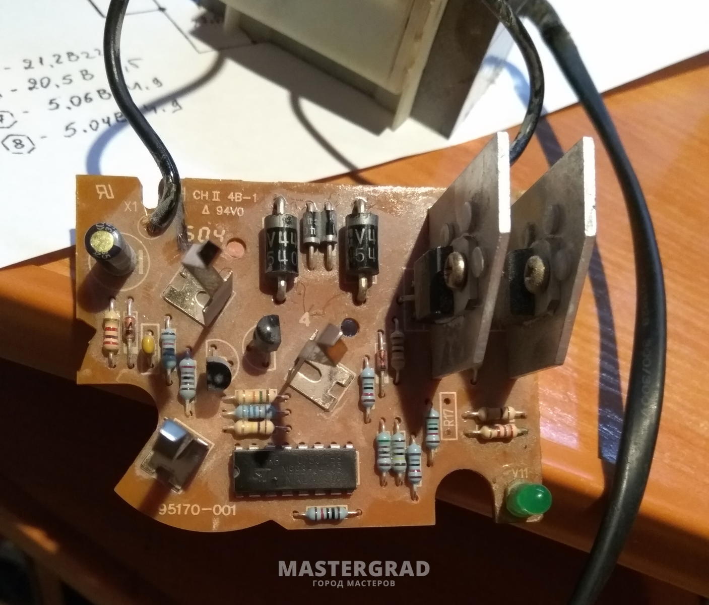
The first two photos show the same board, the same charger:
[
]( )
In the following photos, a light resistor closest to the microcircuit, R5 - 100 kOhm, according to your circuits. Pay attention to it, I needed to rewire and check all the transistors, diodes, and theristor. until I noticed that under the layer of varnish there is no leg of this resistor.
[
]( )
This photo clearly shows the marking of the microcircuit, I do not know who needs it or will help, but this has been asked more than once:
[
]( )
In the last photo, I showed that I changed the thyristor 208 to 408, there were no other options in the store, I will return my own:
[
]( )
Thanks to all of the above unsubscribed for advice and help!
Hello. I'm glad that the problems with the chargers have been solved. And I have a problem with the battery. It’s dead, it doesn’t hold a charge. The batteries are new metal hydride at 160 rubles / piece. The battery voltage is 14.4V. I thought I could put LiIon 4pcs instead. Someone can tell the charger for these purposes needs to be redone, the standard Bosch AL 1411 DV.
rus38 wrote:
. And I have a problem with the battery. It’s dead, does not hold a charge. The batteries are new metal hydride at 160 rubles / piece. The battery voltage is 14.4V. I thought I could put LiIon 4pcs instead. Someone can tell the charger for these purposes needs to be redone, the standard Bosch AL 1411 DV.
It's not that easy (IMHO).
By the maximum voltage during charging, the cutoff can be found, and the finished board can be soldered into the charging, and it is difficult to find at the minimum voltage for such currents for a screwdriver. Unless you just look at it yourself with a compact voltmeter and if anything, run to charge.
In addition, you will need batteries with good current output and with the same parameters. I will roughly count, banks of 8, controller 20, voltmeter 10, total 54ue. You need 2 batteries, one is always not enough. ”Lithium” cannot be soldered, there is a great chance of overheating, only contact welding with nickel strips, you will hardly do it yourself, you need to carry it to the specialists for repacking, this is still a lot. Think for yourself.
rus38 wrote:
. And I have a problem with the battery. It’s dead, does not hold a charge. The batteries are new metal hydride at 160 rubles / piece. Battery voltage 14.4V.
Battery brand? Did you measure the voltage on each bank under load?
The fact that the battery died is undoubted. The voltage on the banks under load did not measure, but the self-discharge is simply amazing. In a week, the entire charge evaporates. And the charged one does not last very long. The banks cost 2.4 Ah, standard Boshevsky ones. BUT if you change, then change everything. . Is there a point to put new ones with half-killed? There are more capacious “Minamoto MH-3000 SC / HP” on sale. For soldering Li-Ion, you can try the Rose alloy so as not to overheat. banks, do not mind if they burn.
rus38 wrote:
I thought I might put LiIon 4pcs instead.
see if this option will be more useful ”> is still using the rework.
An interesting idea. You get a native charger in the trash, buy a Chinese one, remake the battery. Isn't it possible to transfer the charger itself? I have a lipo screwdriver, there on the battery +, -, Thermal sensor, B1 and B2. Connectors B1 and B2 are the most incomprehensible and mysterious .3 accumulators in the battery.
rus38 wrote:
Isn't it possible to transfer the charger itself?
Yes, it can also be redone, but you will also need to buy a balancer and a 14 volt power supply
rus38 wrote:
Connectors B1 and B2 are the most incomprehensible and mysterious.
these are balancing connectors, they track the voltage on each of the 3 batteries in the battery
Redesign of chargers and more
rus38 wrote:
It turns out a native charger for the trash, you buy a Chinese one, you redo the battery.
With "lithium" (the young lady is capricious and wayward), "jokes" are bad, he does not forgive, like the good old "cadmium" overcharge with overheating or overdischarge.
Therefore, it is weighed with a lithium balancer with temperature sensors. And such controllers are built into any lithium battery (phone, laptop, fotyk, shura, etc.).
Lithium cannot be exploited without "brains" for both charge and discharge.
On cadmium, if a recharge has already started due to too long charging, it heats up a little for itself, and if which bank of the entire bundle was discharged more than others or is discharged, or the capacity is different, the excess energy is relatively safely transferred into heat and is safely distributed between the cans and that's all, there is nothing to be afraid of.
And lithium, if you recharge it, there will be a fire or broads, and if you recharge a couple of times deeply, death in the form of a premature and inevitable loss of capacity.
So, in order to insert the battery and the charger and forget, and not touch it and not look or be on duty near it with a voltmeter, lithium should be automatically controlled by checking the personal voltage on each bank this time (this is a cut-off for max.voltage) and temperature sensors- that's two.
In smart chargers, there is also a balancing circuit, which, during the charging process, regulates the charging current on each bank, depending on its degree of wear.
(Although Bosh-baby does not have such a balancer during charging, as in most chargers for shura)
And during operation, the controller looks so that there is no voltage drop again on each bank, it just sharply cuts off the load.
Thanks for the detailed clarification. The question is, do balancing chargers have temperature tracking? In my opinion, they do not even look at the thermal sensor at all. They can glitch and limit the current on a sick bank, then the thermal sensor would be reinsured. Or what kind of resistor can burn out in the balancing circuit and it will blow up in full. Or is it all very unlikely?
rus38 wrote:
do balancing chargers have temperature tracking?
rus38 wrote:
Or is it all very unlikely?
lithium phones
Redesign of chargers and more
My traffic burned out on Bosch AL 1411 DV, is it 15v-1A or 18v-1?
Charger Bosch AL60DV 1419 7.2-14.4 v, the battery says 14.4 v 2.4 Ah
I insert the battery (battery voltage 14.74) - the diode does not light up and does not blink.
If “” akk put on the charge, and overturning the K-E at V7 “” —- 18.34 v
all contacts are soldered. whole diodes. a thermal sensor on a 6.08kOhm battery, I don't know where to dig.
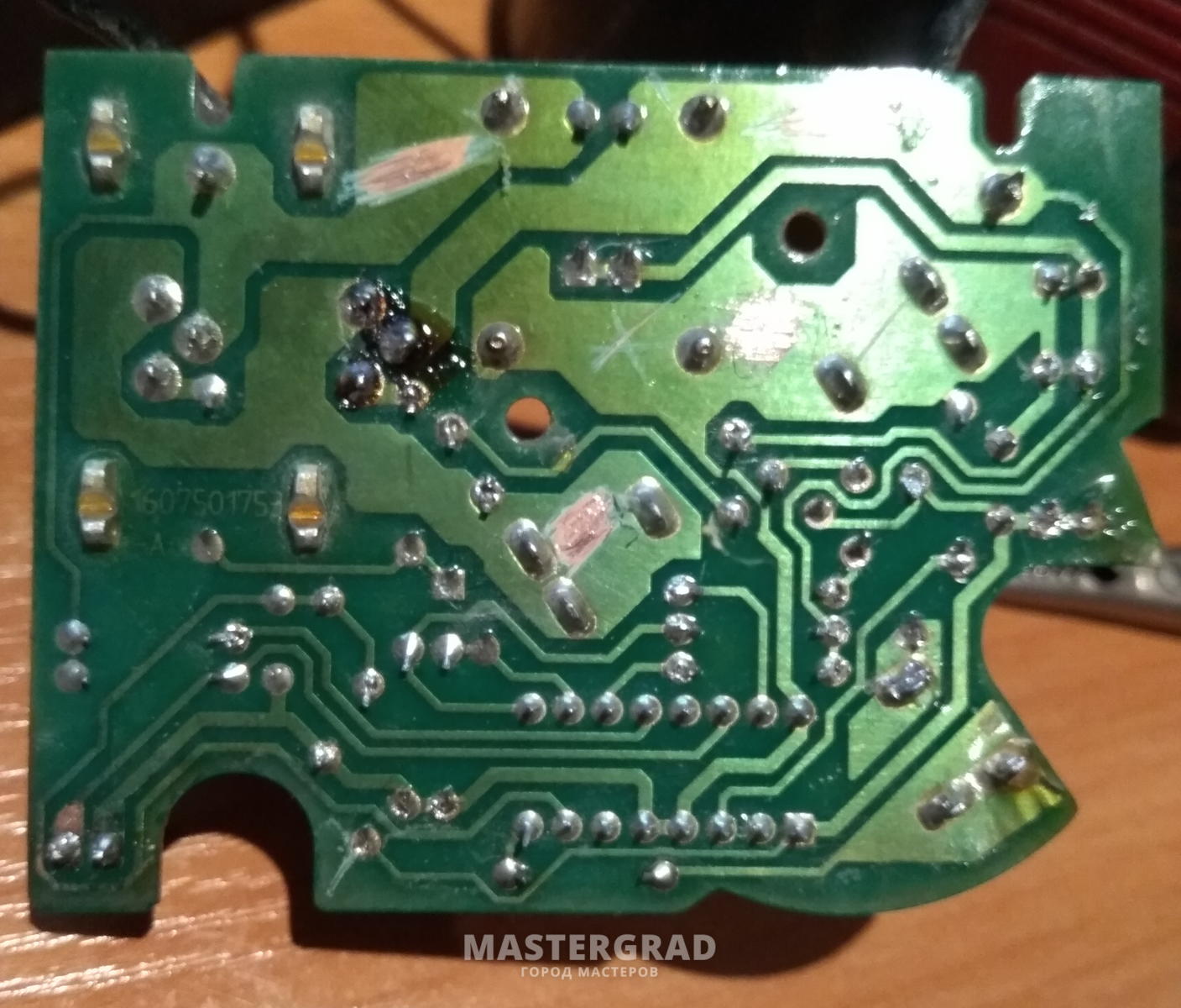

On TYN 208, the trance goes directly, and not like in the circuit - through the diodes!
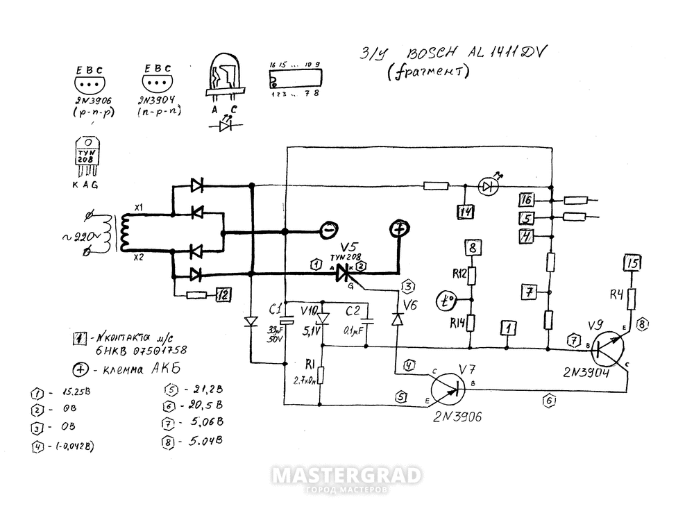

/ the diagram is similar to the one drawn above - does not fit my ../
Measurements: - on the minus
1- 7,5
2- 0
3- 0
4-(-0,9)
5- 22,8
6- 4,5
7- 4,9
8- 4,9
Balu0389 wrote:
Charger Bosch AL60DV 1419 7.2-14.4 v, the battery says 14.4 v 2.4 Ah
I insert the battery (battery voltage 14.74) - the diode does not light up and does not blink.
If “” akk put on the charge, and overturning the K-E at V7 “” —- 18.34 v
all contacts are soldered. whole diodes. a thermal sensor on a 6.08kOhm battery, I don't know where to dig.


On TYN 208, the trance goes directly, and not like in the circuit - through the diodes!


/ the diagram is similar to the one drawn above - does not fit my ../
Measurements: - on the minus
1- 7,5
2- 0
3- 0
4-(-0,9)
5- 22,8
6- 4,5
7- 4,9
8- 4,9
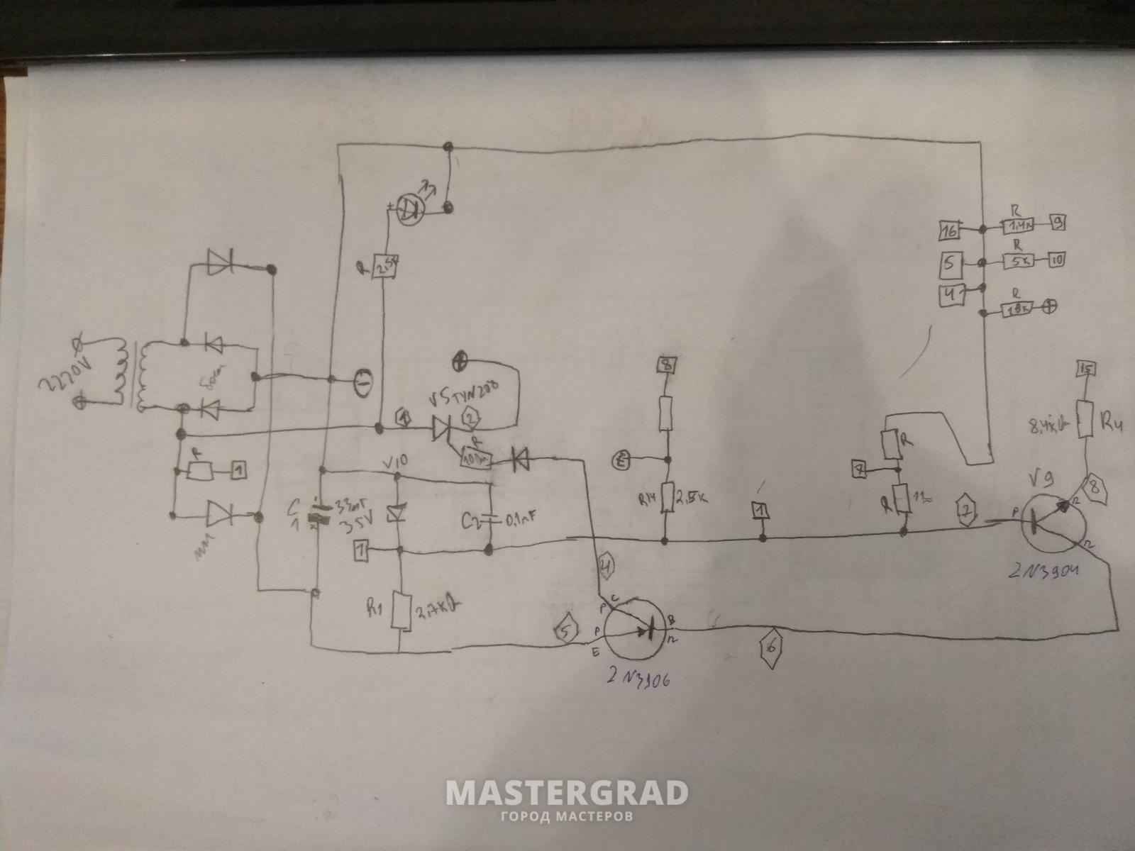
Ivan_90, For those who have the same question, I will answer (better late than never): The transformer is exactly 18V at the output. The power is 28W (declared on the charger case) Bosch AL1411DV, therefore the current should be approximately 1.5A. In short, the transformer is 18V 1.5A at the output. Moreover, the use of a low-frequency transformer (linear power supply unit) in this charger is not accidental, it charges not with a direct current (DC) voltage, but with a pulsating voltage of 100Hz (50Hz double half-waves taken from a 220V city), without a smoothing capacitor. According to some reports, this mode of charging Ni-Cd batteries is quite effective.
I'm not sure if the transformer burned out. It may have overheated and the thermal fuse has tripped. In this case, the transformer can be restored! The thermal fuse in this transformer is tied to the winding from the outside, if you remove the cover from the windings from the side of the 220V input, then you can try to replace the thermal fuse. The terminals of the thermal fuse are connected to the extreme petals of the transformer from the groan of the 220V input. There must be resistance (DC) between the outer petals
0 Ohm - thermal fuse. The winding (primary) is connected to the right and middle petals - resistance (DC)
90 Ohm. A 220V cord is soldered to the left and middle tabs. If the primary winding (middle and right petals) ring, and the extreme petals do not ring among themselves (resistance - infinity), then you just need to replace the thermal fuse! It is better to restore the native transformer than the one that was found.
There is some confusion about how to properly name the TYN208: call it “SCR” or “thyristor”. The fact is that in the USSR, the whole family of controlled diodes, including dinistors, trinistors and triacs, was often called thyristors.However, the word trinistors probably did not take root, and they began to call what the old writer calls “trinistor” as a thyristor. And SCR (just SCR) is the marketing name for "trinistra" or, as it is more understandable, thyristor, i.e. controlled unidirectional diode with an unlocking contact (three outputs).
Help with the subject.
Symptoms: You plug it into an outlet - the indicator lights up constantly.
Connect the battery - the indicator will blink and light up constantly. (When I was working, it blinked until the end of charging, then it was constantly on.)
Accordingly, the battery is not charged.
The transformer is working, the diode bridge is normal.
There is no voltage at the terminals (without a connected battery). (Should it be? If the third terminal hangs in the air, should there be voltage?)
The battery was temporarily taken away, I can not check the voltage under load.
Does it make sense to check the TYN208 thyristor (V5 on the radiator) or is it most likely in the control?
Microcircuit 6HKB 07501758.
Visual inspection did not reveal a problem. There was a suspicion of poor soldering at the V5, if it was soldered - the result is the same.
Charging is a bit similar to BOSCH AL1419DV, here the diagram was given: ">
This diagram is:
Available tool: multimeter, soldering iron. No oscilloscope.
Forum of the Kostroma Jedi → Flea market → BOSCH screwdriver charger repair required
Pages 1
You must login or register to post a response.
The charger AL 1411 DV has failed. Who knows if it makes sense to repair it, how much will it cost, or is it better to buy a new one?
Pages 1
You must login or register to post a response.
Forum of the Kostroma Jedi → Flea market → BOSCH screwdriver charger repair required
If your DVD player breaks down, you don't have to throw it away or take it to a workshop and pay money for repairs. You can disassemble and even repair the device yourself.
The player consists of a body with a tray for loading a disc. On the front panel of the case there are: a status display, buttons for controlling the player, on some models there may be connectors for connecting a microphone, headphones, flash drives. Everything inside the case is much more interesting.
Briefly about the main components of the device.
This is the main element of the player. It consumes electricity from a switching power supply.
It is used to read information from a carrier. A wide flexible ribbon cable connects the reading head to the main board. All disc media have an installation track required for proper operation. It is located in the center. When a disc is loaded, the laser is shifted towards the center to read this track. If the reading is successful, the presence of the disc is established, and only after that the rotation motor is turned on and the disc begins to play.
The motor communicates with the processor through the driver. The rotation speed of the disk depends on the signals from the processor.
This is a microcircuit that receives commands from the processor and controls the operation of the spindle drive motor, laser lens focusing coil, laser reader movement motor, tray loading and unloading motor.
“How many devices and wires! I'd better take it to the workshop! " You say in horror, clutching your head. But! Don't rush to waste your money. There are some breakdowns that can be easily identified and repaired with a conventional screwdriver.
There could be many reasons for this. Let's consider the most basic and common ones. Let's remove the cover of the player and diagnose the power cord for internal damage. To test the operation of the multimeter, turn it on in the resistance measurement mode. We connect the probes to each other. If the device is working properly, then the display will show zeros. We attach the open probes to the cord. One probe to the cable contact at the junction with the board, the other alternately to one of the plug contacts. If the ohmmeter gives up to 3 ohms, the core is undamaged. If more, then there is a break in the core, and the cord must be replaced. If the multimeter does not react in any way, then the contact on the plug and on the opposite end does not belong to the same conductor of the electrical wire.It is not recommended to use the multimeter in the dialing mode, as it works in the range from 0 to several hundred ohms. The next step is to inspect for dust and swollen capacitors. We remove the dust, change the capacitors. If no visual faults are found and the replacement of the wire does not change the situation, take the player to a workshop.
The video below shows how the multimeter works.
Let's consider the main causes of breakdown and how to deal with them.
Reasons: the laser head is dirty or the laser is out of order.
The contaminated head is blown out with compressed air using a conventional rubber bulb. The objective lens is wiped with a cotton swab moistened with alcohol. Do not use solvents. You need to wipe it very gently with light movements. If cleaning is not sufficient, the head must be replaced.
The train often breaks at the folds. We disassemble the player in the same way as when servicing the laser head. Carefully remove the cable from the plugs. We examine. If there are visible tears along the edges, and you do not want to completely change the train, we make preliminary repairs. We cut off the place of damage with scissors. Remove the insulation layer with a knife or blade so as not to break the metal strips. If it doesn't work out neatly, then you can try to remove the insulation with a medical needle or zero sandpaper. The width of the removed layer should be the same as that of the cut piece of the train. Remove the blue plastic end plate from the trim and similarly glue it to the updated edge of the train using super glue.
Now, when visually the train seems to be intact, we call its contacts. We attach one probe to the contact at one end, and the other one at a time to all contacts at the other end. We do the same on the other side of the train. Each contact should call with one contact on the other side. If a contact rings with several, then there is a short circuit in the loop. If the contact does not call with any other, then the loop is open. And in fact, and in another case, the cable is not subject to use. It needs to be replaced.
If the motor rotates unevenly or does not rotate, then it must be replaced together with the attachment.
When the cover of the player is removed, plug it in and press the eject button. Since the tray itself is not able to slide out, you need to push it slightly. But do it carefully so as not to get an electric shock. The cover will slide open and disconnect the player from the network. We take a stick with wound cotton wool and moisten it with alcohol. We wipe the rails of the tray. Press the button. If the problem is not fixed, unscrew the necessary screws, remove the strips, plastic covers and get to the belt.
We change the belt and collect everything back. The video below shows a detailed replacement of the computer drive belt. We work in the same way in the DVD player.
Most flash drives are natively NTFS format. You need to insert the USB flash drive into your computer, copy the necessary information to your hard drive, right-click on the USB flash drive and select "Format". Next, select the FAT 32 format, agree that all data will be lost and click ok. If the DVD still does not see the USB flash drive, then the problem is in the electronics: the microcircuits may be damaged or the power supply in the wires or cables is interrupted. It is worth contacting professionals.
Updating your device won't get you all the trouble. The player can be Russified with the firmware. It will produce larger films, and errors in reading supported formats will be eliminated. But the player will not be able to read formats that were not previously supported. Therefore, if the device works without lags, do not update it.
In order to find out if it is possible to flash your DVD player, you need to carefully read the device model on the back cover. Go to the manufacturer's official website and view the firmware for this model. If they exist, then download the latest version to your computer, burn it to a CD. We start the disc in the player. When the update is finished, the start-up screen appears on the TV or player screen and the disc tray automatically pops out.
In addition to problems that can be fixed by any user who knows how to work with a screwdriver and pliers, there are no less common, but more complex problems:
- display backlight does not work;
- distortion of sound;
- there is no picture and sound;
- no picture or sound;
- the "karaoke" mode does not work;
- there is no color image;
- complex mechanical damage, including water ingress;
- breakdown of the power controller;
- failure of microcircuits.
All of them require the ability to read electrical circuits, the presence of special devices, soldering stations. If you are not a radio technician, then it is better to turn to professionals.
There are many manufacturers of DVD players. The principle of operation and the main elements of the devices are the same. Therefore, the repair of turntables from different manufacturers is the same. If you have a desire to try to repair the player yourself, go for it. Perhaps you will succeed, and you can help your friends another time. Or maybe you will like it so much that you will be engaged in radio engineering and open your own business.
The Bosch charger 2.607.224.392 is suitable for Bosch NiCd and NiMH batteries with a voltage of: 7.2 V; 10.8V; 12V; 14.4 V. This is a quick charger that has Delta Voltage charging control. At the end of the operation, a sound signal is emitted. The ability to use this charger with various batteries expands its scope.
The manufacturer reserves the right, without notifying the dealer, to change the characteristics, appearance, equipment of the product and the place of its production.
The specified information is not a public offer
I was looking for a charging circuit for a long time, the Bosch AL1450DV charging circuit was not found (only after repair).
Charging the green LED has stopped lit
Inside there was a power supply unit more complicated than a computer
I checked all the transistors of the microcircuit, I did not notice any special deviations. All high-quality capacitors are normal with ESR, too, below the permissible value.
Burned key transistor- STP5NK80Z - STP5NK80ZFP N-CHANNEL 800V - 1.9W - 4.3A TO-220 / (TO-220FP-less power) Zener-Protected SuperMESH ™ Power MOSFET The presence of the letters FP in the marking means an insulated case (maybe in principle when using a radiator). The transistor is uniquely a MOSFET. Transistors marked 5N60, 5N80 are suitable for replacement. Also BUZ90 and others will do, for example from the IRF series.
It was a resistor of an incomprehensible value, who knows which one?
The standard circuit of the pulse charging regulator on the UC3842 is almost like that of the Bosch AL1450DV
Power resistor 220V b. order 75-100Com, it heats up quite strongly, it is better to put 2 W (put some 2 W about 80K).
Replaced UC3842 (can be replaced with UC3843), Optocoupler CNY17F-2, LM358.
There was a suspicion of 16 feet ms. But no one could find any schematics or datasheet on it. Find .pdf on m / s 6HKB 07501758, but to no avail. 6HKB07501758 was the only one who found out that the manufacturer is STM ... ..
Here's what is written on her case:
? HUI 0750 1833 / 1 line
B GK390TT / 2 line
VM99 CHN / 3 line
0750 L9L4 / MKL
L GK8080LW
V6 99 CHN
Maybe someone knows what this ms is and how it can be replaced?
MAX712/ 713 MAX8213 / 8214 (something similar?) - 16 feet
ICM7556 -14 (8) legs wrong
With Bosch chargers, everything is quite funny))) their microcircuits are on a special order ...
I advise you to pay attention to m / s MAXIM2003 (analogue of bq2003). It can be used to implement the required charger. Or max713. In KIT and ready to give.
Someone says that 6HKB07501758 dies when a dead battery is connected, but this is not our case.
I didn't want to blow up anything else, so I connected the charging (according to the method) at 36V alternations, having previously soldered another 20KΩ to the ill-fated resistor in parallel. The block squeaked and blinked a green diode. Nothing has warmed up, there are no short circuits. We solder it with 20K and plug it into the network - everything works, the resistor heats up noticeably, as it was intended.
Lastly, a little extra. battery information
I assume that the 3rd contact is a thermistor for monitoring the temperature of the battery. This is the 2nd end connected to the minus. Resistance is 10 kohm
At the moment, I want to know what is in the native Bosch batteries.Most likely a thermistor, because the contact on the board is signed “NTC”. I hung a 10 kiloohm permanent resistor between the third leg and the minus of the battery - an ordinary flight, it charges. Unfortunately, there is no Bosch battery at hand - maybe someone can look at the type of thermistor and put out the rating or a photo of the detail.
different accounts:
12v 1.2Ah (2003) = 6.9kOhm
12v 1.2Ah (2003) = 7.7kOhm
12v 1.5Ah (2008) = 7.8kΩ
14.4v 1.5Ah (2007) = 6.1kΩ
12v 1.5Ah (2005) The resistance of the resistor is 6.19 kiloOhm, it stands between “-” and “C”.
In hitachi, the charge sensor turns off the charging at a resistance of 2.85 kOm. You can ring the rest of the batteries, rather than the contacts coincide
Disconnection occurs from the temperature of the battery cans (+55 ″ С)
More
Let's compare the characteristics of 2 chargers:
Bosch AL1419DV charging current 1.9 A -1100 r.
Bosch AL1450DV charging current 5 A - 3000 r.
The voltage of the batteries being charged is uniform: (7.2 ... 14.4 V) both are suitable for charging NiCd and NiMh.
The 1450 will simply charge the 2.6 Ah battery in 40 minutes, and the 1419 in 1 hour 45 minutes.
cash price
cash price
BOSCH service center address:
Novosibirsk, st. Sibrevkoma, 2, office. 02
1. Warranty conditions
1.1. Warranty service and repair of Bosch, CSTBerger and Skil measuring equipment in compliance with the manufacturer's requirements and standards are carried out in the Russian Federation only in the branded or authorized service centers of Robert Bosch LLC.
1.2. The service department of LLC "Robert Bosch" considers warranty claims only if there is a correctly completed original warranty card and sales (cash) receipt, invoice confirming the date of sale.
1.3. The warranty period is calculated from the date of sale to the consumer and is:
- professional tools and measuring equipment (blue color of the case) - 12 months; when registering on the site within 4 weeks from the date of purchase, the warranty is extended for another 24 months;
- household tools (green body color) - 24 months; when used for professional purposes, the warranty period changes by 12 months;
- Skil measuring equipment - 24 months; if used for professional purposes, the warranty will be void;
- CST / Berger: depending on the type of tool, the warranty ranges from 12 to 24 months; full information about the warranty period is posted on in the event of a dispute, the period indicated on the website is considered correct.
1.4. During the warranty period, the following are eliminated free of charge:
- damage caused by the use of low-quality material;
- defects in assembly, admitted through the fault of the manufacturer.
The service life of Bosch, CST / Berger power tools and Skil measuring instruments is 7 years.
2. No warranty provided
2.1. Mechanical damage (cracks, chips, scratches) and damage caused by exposure to aggressive environments, high humidity and temperatures, foreign objects entering the ventilation grilles of the power tool, as well as damage resulting from improper storage (corrosion of metal parts). For electrical cables with internal and external mechanical and thermal damage.
2.2. For tools with malfunctions due to overloading, non-observance of the instructions for use or improper use, improper use of the tool or the use of improper accessories.
2.3. Normal wear and tear of the tool (full depletion of the resource, strong external or internal pollution).
2.4. On parts subject to natural wear and tear.
2.5. For replaceable accessories (chucks, collets, tires, sprockets) and work equipment (saws, drills, cutters, saw blades).
2.6. An instrument opened or repaired during the warranty period outside of Robert Bosch Service or an Authorized Service Center.
2.7. To an instrument with a deleted, erased or modified serial number.
2.8. Preventive maintenance of the power tool (cleaning, flushing, lubrication, etc.).
2.9. For battery packs that have completely exhausted their resource.
3. Operation of the service center and customer signature
Certain power tools and measuring equipment require periodic maintenance; this is reported in the instructions for the product.
The work of the workshop for carrying out maintenance is carried out in accordance with the current rates of the service center. All malfunctions identified during maintenance that are covered by the warranty are eliminated free of charge, and non-warranty defects are eliminated by agreement with the consumer in accordance with the established procedure.
The client's signature is a confirmation that the client is familiar with all clauses of the warranty conditions, instructions for the instrument, understands them and agrees with them.
There was nothing to do - it was necessary to save the device, and curiosity worked, but what was the problem (you understand me), so I got comfortable and warmed up a kilogram Soviet soldering iron for a hundred watts (alas, there was no more convenient soldering iron in the whole village).
After half an hour, the soldering iron warmed up like an oven. The player itself showed no signs of life. After opening it, it turned out that the fuse had blown, the electrolyte after the diode bridge at the power input and another electrolyte on the 12 Volt bus, already at the power supply output.
Since the components were strained, the fuse was wrapped in foil and put in place. The electrolyte on the 12 Volt bus with a capacity of 1000 μF was replaced with 470 μF, and the capacitor was found in the power supply unit from the SEGA prefix.
The first electrolyte - on the rectifier, turned out to be completely working, only for some reason it swelled up, it was not replaced.
After turning on the player started working as good as new, but after examining the power supply board, it became clear that the unit is working in an abnormal way - an incomprehensible overheating of the diode bridge, some limiters and even capacitors. The player was left on for an hour - the heat dissipation turned out to be stable, who knows, it may have been terribly hot at the beginning, but it works very well. Best regards - AKA KASYAN

There are two possible reasons:
2. Malfunction in the DVD drive.
For example, DVD HYUNDAI we will consider one of the options for repairing a DVD drive with our own hands... At first, the DVD “stopped reading discs”, and the malfunction sometimes manifests itself and disappears, as a result, it stopped working altogether.
First, we always check the output voltages from the power supply. Is the voltage normal? Then we look at the disk drive, for this we unscrew it and disconnect all the connectors.
We check visually connectors, cable, soldering, etc.
If the visual overview didn't give anything, let's move on.
Next, you need to ring the loop that goes from the board to the head.
During operation, the drive head constantly moves from place to place. As a result, it turned out that the four outer conductors of the loop are in a cliff, the rest are already ready to come off too. I tampered with the insulation with a needle. Here you can see the broken tracks.
If the break is at the very beginning or end of the loop and its length allows it, then you can carefully cut the end of the loop with scissors and insert the loop into the connector.
But sometimes it is useless to repair the loop, it is constantly in operation, it moves and bends, if it is soldered, it will break off again after a while. We need to change. But the problem is to buy exactly such a train is very difficult. But there was a way out! An old, unusable drive from a computer turned out to be at hand. True, the train from it is wider and longer, but the distance between the conducting lines and their thickness are the same.
But it's even good that it is longer, because it will bend less, and there is enough space for it. Contacts fit perfectly, one to one!
We accurately measure the required width of the train, it is better to make it a little wider, and then carefully trim it to the desired width. Everything must be done carefully, especially the edges of the train. Now we put it in place.

We check the operation of the drive. So that the train does not cling to anything.
Putting the DVD player together in reverse order. We put the drive, board, cable and connectors in their places, close the case, and enjoy watching your favorite films
Good luck with the repair! Visit our Forum.

It operates over a temperature range of 0 to 100 ° F (-20 ° C to + 40 ° C) and converts to a frequency ranging from 0 to 1 kHz.
With years of experience working with various American Power Conversion UPS models in harsh rural grid environments, we share tips you won't find in a technical manual or any other book. You will learn how to extend the life of a UPS or even resurrect a unit without being an electronics engineer and not having any measuring equipment at hand, except for a Chinese multimeter. More details ...

| Video (click to play). |
The disadvantage of the prototypes of this device can be attributed to the fact that they are focused on solving only a narrow measuring problem, namely, determining the air permeability of a knitted fabric, taking into account its actual density.


