The air heating device Planar, produced in Samara, is very popular. If there is not enough heat in the car, it is an indispensable assistant, even in the most severe winter domestic weather. In the cabin of a small passenger model or a spacious van, the driver and passengers become as comfortable as possible in a short time period.
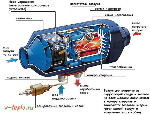
The operation of the device is based on a simple principle - the drawing of surrounding air masses into the heating chamber. When fuel burns, heat energy is released. It is sent to heat the air, which then enters the interior of the cabin.
One of the advantages that a planar heater has is the ability to adjust the heating power. To do this, the device has a special knob on the regulator, which is easily rotated and set to the desired position.
Having set the desired power value, there is no need to interfere with the further operation of the device. It will be controlled automatically:
The Planar heater device includes not only a power regulator in the form of a rotary knob, but also a timer. The latter is necessary in order to turn off the installation after a long work.
The device is designed in such a way as to make the work autonomous in all aspects. Automation also monitors the current state of each work item located inside. The ignition process starts only when the control element makes sure that all nodes are in good condition. This achieves a very high level of safety during operation.
To ensure that the resulting flame remains within the normal range, it is controlled by an appropriate indicator. If the temperature limit is exceeded, the control unit will stop burning.
Despite the high level of automation, turning off the device is supported in manual mode. The combustion chamber begins to ventilate. The fuel supply is completely cut off.
VIDEO
Some features of the Planar heater device
As a rule, fuel enters the combustion chamber of the device directly from the fuel tank of the vehicle. However, this option is not the only one possible. Sometimes the device has its own container, into which the fuel necessary for operation is poured.
By analogy, electricity supply is arranged. The planar heater is powered directly from the car battery.
The number of components of the heating device is huge, but among them there are three main elements:
Control panel or block - necessary to control the operation of the device as a whole
Fuel pump - necessary to supply the required amount of fuel to the storage room
Heating element - it heats the air, which subsequently enters the car interior
You may also be interested in our article on electric heating
Of course, the Planar heater is very useful and indispensable in cold winters. However, many motorists do not risk installing it, as they are afraid of incorrect operation in emergency situations.
Engineers took into account all the possible features of the operation of the device in various conditions. Let's consider some of them:
The operation of the heater is constantly monitored by automation. If it is faulty, a warning LED (orange or red) lights up
The device will not allow the heat exchanger to overheat - in such a situation it will turn off
There are cases when the combustion stops for spontaneous reasons - in such situations, the installation also automatically shuts down
As a result of an unsuccessful start of the heating equipment, the automation will make several restarts. If each fails, a failure warning will be issued.
Constant power surges can be very unsafe. The control unit will ensure the operability of the device only in situations where it does not go beyond the normal:
Onboard voltage 12 V (device 4DM-12) - from 10.5 V to 16 V
Onboard voltage 24 V (device 4DM-24) - from 20.5 V to 30 V
Often the cause of overheating is incorrect installation of equipment. It occurs in those cases when the inlet and outlet of the heater were blocked.
Among car owners, especially truckers who spend most of their time on the road, the planar heater deservedly receives a lot of positive feedback. Domestic development, in comparison with imported analogues, is reliable, but less expensive.
In a large number of positive characteristics, there are:
By passing the air vent pipes into the cargo compartment, you can heat the entire car, and not just the driver's cab
Even at significantly low temperatures (less than -20 degrees), their efficiency remains at a very high level.
Saves fuel and battery life
Sufficient power rating
Unlimited installation time
The planar heater is widely used in vehicles used to transport medicines, drinks, animals, process fluids, etc. They are actively used by drivers of kuguns, cranes and other special equipment.
To use the Planar heating unit, there is no need to start the car engine. This makes it possible to continue to operate it during the night.
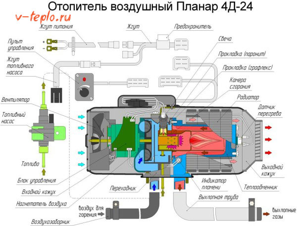
There are several models on the market, each of which is characterized by its inherent features. However, the Planar-4dm 24 model is considered the most popular among them. Its installation is possible not only in large vans, but also in change houses, booths, etc. During operation, the heater practically does not make noise.
One of the main aspects of using the Planar heater is compliance with safety regulations. Consider the most significant rules:
If the device has been turned off, it can only be turned on again after 10 seconds.
Do not turn off the power during the purge cycle
The heater must be disconnected from the mains if the body is subjected to welding work.
It is recommended to turn off the device when refueling the vehicle.
The heater must not be used indoors.
Having installed such a device, you must have a sand bucket and a working fire extinguisher nearby.
It is forbidden to lay fuel pipes inside the car, however, they must be reliably insulated from the outside.
In the event of a breakdown, it is not recommended to engage in independent repair of equipment.
Everyone can install a planar heater independently. However, for greater confidence in its subsequent reliability and performance, it is recommended to entrust this process to a professional.The cost of services is relatively low and significantly lower than the cost of possible restoration or repair.
The considered device for heating cars in the winter or small, but necessarily well-ventilated premises (gatehouse, change house, etc.), is in demand. However, despite the many benefits, cost can be a barrier. Average prices for various models start at 18 thousand rubles.
As mentioned earlier, the installation of heating equipment can be done independently. In order to save time and for greater reliability, you should contact a specialist whose service cost starts from 5-6 thousand rubles.
Autonomous Planar is an air heater developed by Russian specialists and manufactured in Samara. The model range of these car heaters consists of four devices (Planar 2D, Planar 4DM2, Planar 44D, Planar 8DM), each of which is available in two versions - 12 and 24 Volts. Even in severe frosts, such an installation can provide the optimum air temperature in the car. First, we will briefly consider the device and the principle of operation of the heater, and then we will study all the Planar errors (fault codes) and their decoding.
Autonomous heaters "Planar" are equipped with a power regulator and a timer. The installation can work autonomously at all stages. Electronics starts ignition only if the various components are in good condition and the required conditions are met. Therefore, you should not worry about the safety of using the device.
The main components of the Planar autonomy:
block with control panel;
a heating element;
fuel pump.
The heaters of this manufacturer work on the principle of supplying outside air to the heating compartment. During the combustion of fuel, energy is released that heats this air. Only after that hot air is supplied to the interior of the vehicle.
To select the optimal power, a special regulator is used with the possibility of fixing in a given position. After the user selects the optimal operating mode, the heater will independently maintain the set temperature.
The basic principle of operation of the Planar autonomy:
Purge of the combustion chamber.
Heating the glow plugs to the required temperature.
Supply of the optimal ratio of air and fuel to the working chamber.
Combustion of the air-fuel mixture.
Turning off the candle after stabilization of the temperature mode selected by the user.
We decided to publish the Planar autonomous fault codes in the form of four tables. Before each of them, a specific model of the heater is indicated, which will help you understand what the problem is in your case.
Service center "Dakar-Auto" installs, maintains, diagnoses and repair autonomous heaters planar for trucks. According to the accumulated statistics, the main causes of breakdowns are low-quality fuel, long service life, violation of operating rules and excessive use.
Heater diagnostics.
Replacement of candles, casing, tank, heater body.
Replacement or repair of the control unit (control unit).
Air blower replacement.
Dismantling, cleaning of carbon deposits and dirt, replacement of combustion chambers.
Replacement of the electric cable, overheating and flame sensors.
Fuel pump replacement.
Comprehensive repair of heater units.
If you need to repair the part separately, then before you remove it and bring it to autonomous heater repair to the service center, you need to write off the error code, but it is better to send a photo in advance. To clarify the error code on mechanical models 4DM you need to count the number of blinks of the LED, and on electronic 4D rewrite the numbers displayed on the remote control.
After diagnosing and assuming a malfunction, drivers often decide to repair the autonomy on their own.However, it is difficult for a non-specialist to understand all the nuances and perform the adjustment of the unit without errors. One of the features of the built-in diagnostics is the display of a failed circuit without specifying the specific part of the failed circuit. In some cases, several nodes may break, which will complicate the identification of a malfunction and the repair of the heater. Only qualified craftsmen can quickly cope with this task.
Accumulated soot on the evaporator grid, melted contacts and candles, combustion products on other parts can cause the control unit to fail. As a result planar (Planar) will issue incorrect codes for Planar 44D and other models. In this case, only specialists can identify the cause of the breakdown, and do-it-yourself repairs can lead to disastrous consequences or an increase in the cost of the entire process.
Modern repair equipment and several diagnostic stands.
Availability of original and non-original components and spare parts.
Repair of heaters Planar discontinued, including models 4DM 24, 4DM2, 4DM2 24, 44D24 .
Masters who are well versed in malfunctions and adjustment of heaters.
Warranty on work performed and replaced parts and assemblies.
The service center "Dakar-Avto" will restore the functionality of the Planar heaters as soon as possible. We stock a wide range of Planar heaters at attractive prices. Sign up to our service by phone +7 (495) 125-00-11 and your car will be warm again!
Prestarting liquid heaters and autonomous air heaters
Message Petrov_kamensk » Jan 13, 2012, 05:57 PM
do not invent, all typical questions have answers in the instructions, those who are too lazy to read go to the forum and ask the same question, BUT even answers are given to this.
Message autonomka34 » Jan 13, 2012, 08:28 PM
Message autonomka34 » Jan 13, 2012, 08:58 PM
Message Ratibor77 » Jan 16, 2012, 08:17
Here I'll tell a story.
In my opinion, everyone should mind their own business.
Message Petrov_kamensk » Jan 16, 2012, 09:07
Vasily Ivanovichi told you
Message ViktorFD » Feb 21, 2012, 09:46
Message Petrov_kamensk » Feb 21, 2012, 10:04 am
Experienced recommend Only vertical installation with a deviation of 5-10 degrees.
Message ViktorFD » 21 Feb 2012, 19:33
Message zero » Jan 02, 2013, 13:45
Sorry if something is wrong with the shooting, we were not experienced 🙂 Put a better like and we will try to shoot better for you 🙂
Hello, I have a planar 44d-12 thick smoke does not start and error 13 pops up sometimes 8, and when you torment it for a long time it starts and snorts straight from the muffler. I thought I bought a new pump, changed it, the problem remained, the hair dryer worked for 5 months at the most. Tell me what can be?
In any case, you need to clean the burner and boiler, then check the gap on the impeller of the air blower, as the manufacturers say, it should be from 0.25 to 0.4mm, a large gap will affect the operation of your heater. Watch our other planar videos to understand how and what to check.
Question
Appointment, repair and replacement of heater components PLANAR-4D-1224;
Heaters PLANAR-4D-12; PLANAR-4D-24 differ from each other in software and air blower.
1. Checking and replacing glow plugs.
The glow plug ensures the ignition of the fuel mixture during the start of the heater. Check the performance and replace the spark plug as follows:
– remove the heater from the vehicle;
- unscrew the screws securing the spark plug cap and remove the protective cap of the spark plug.
– unscrew the screws securing the casings, remove the casing
– disconnect the connectors pos. 2 (see Fig. 4);
- unscrew the candle pos.1 and remove carbon deposits from it;
- check the insulation resistance of the body of the spark plug with a voltage of 100 V according to fig. 5. Insulation resistance must be at least 10 MΩ.
Rice. 5 - Candle test scheme
- connect the candle to a DC source with a voltage of 12-0,3 In and through
25 seconds to measure the consumed current.
The consumed current should be no more than (3.5 ± 0.5) A, while the heating element of the candle warms up to a bright red color, starting to glow from the tip of the candle. Test time no more than 120 sec. The time between switching on is at least 180 sec.
The spark plug must be replaced if it does not meet the listed requirements.
When replacing a candle, installation is carried out in the reverse order, while making sure that the sealing washer is installed, as shown in
2 Dismantling and replacing the candle grid
The grid is intended for uniform supply of fuel to the combustion chamber.
When replacing or checking the candle, it is necessary to check the grid for the presence of soot or clogging. If soot is found, the mesh must be replaced. Install the grid in the combustion chamber fitting in accordance with Figure 6 until it stops, while first cleaning the hole ? 2.8 mm from possible clogging.
Fig 6- Scheme of installing a candle and a grid in a combustion chamber
Attention !! The mesh should be installed with an interference fit until it stops. If the grid is not installed all the way to the end, failures are possible when starting the heater.
3 Removing and replacing the overheating sensor .
Overheating sensor pos.1 see Fig.7 is used to control the heating temperature of the heat exchanger. When the heat exchanger reaches a temperature above 250 °C, the overheating sensor opens the electrical circuit, and the heater is automatically switched off. The reason for replacement may be the heater shutdown at a heat exchanger temperature below 250 °C or for the reasons indicated in Table. 4.
To avoid errors in assessing the performance of the overheating sensor, it is necessary to replace it with a serviceable overheating sensor. If with new
the cause of the heater malfunction is eliminated by the sensor, then the removed sensor is considered inoperative and must be dismantled.
To dismantle the overheating sensor, proceed as follows:
– remove the heater from the vehicle;
- unscrew the screws securing the spark plug cap and remove the protective cap of the spark plug.
Loosen the cover fastening screws, remove the cover pos. 4 (see fig. 2).
– disconnect the wire contacts from the overheating sensor and unscrew the sensor mounting screws; remove the overheating sensor (see Fig. 7);
- check the cleanliness and reliability of the fastening of the electrical contacts of the wires,
going from the electronic unit to the overheating sensor. If there is dirt or oil on the contacts, remove them with clean suede soaked in gasoline. Upon detection
burn on the working surface of the contacts, clean them with fine glass sand No. 150 GOST 6456, wipe with gasoline and tighten the contacts.
When replacing the overheating sensor, install in the reverse order.
Fig 7 - The main components and parts of the heater
4 Checking, dismantling and replacing the flame indicator .
The flame indicator is used to determine the presence of a flame in the combustion chamber. It is a tube with a built-in thermocouple with two leads.
Check the flame indicator as follows:
– remove the heater from the vehicle;
- unscrew the screws securing the spark plug cap and remove the protective cap of the spark plug.
– unscrew the screws securing the covers, remove the covers pos. 3 and 4 (see fig. 2).
– disconnect the indicator wire contacts from the connector of the control unit pos. 3 (see Fig. 4);
– unscrew the indicator from the combustion chamber housing pos.4 (see Fig. 4).
– check the insulation resistance between the terminals and the indicator housing.
The resistance must be at least 20 MΩ.
– check the resistance between the terminals of the flame indicator. The resistance should be in the range of 3-10 ohms.
Measurements should be taken at normal temperature and humidity. If the indicator is not
correct, it must be replaced.
When replacing the flame indicator, installation is carried out in the reverse order.
5 Appointment, dismantling and replacement of the air blower.
The air blower consists of an electric motor with an attached volute, on the shaft, of which a fan is installed on one side, and an impeller on the side of the volute.
The air blower supplies air to the combustion chamber for combustion,
purges the combustion chamber before the start and end of the combustion process in order to cool and remove the remaining fuel and moisture,
creates an air flow, which, passing through the radiators of the heat exchanger during the operation of the heater, heats up, and also changes the air flow due to
change in motor speed.
If the electric motor or the impeller fails (the impeller touches the volute), the air blower must be replaced with a new one.
To dismantle the air blower, proceed as follows:
– remove the heater from the vehicle;
- unscrew the screws securing the spark plug cap and remove the protective cap of the spark plug.
– unscrew the screws securing the covers, remove the covers pos. 3 and 4 (see fig. 2).
– Disconnect the contacts of the electric motor wires from the connectors of the control unit;
- unscrew the screws securing the control unit;
- remove the spring washer pos.33, the fan pos.25 and the shell
- unscrew the screws securing the air blower to the adapter;
- Remove the air blower.
When replacing the air blower, installation is carried out in the reverse order.
Fig.10 - Air blower
6 Removing and replacing the control unit .
The control unit provides control of the heater together with the control panel.
The control unit performs the following functions:
a) initial diagnostics (serviceability check) of the heater units at start-up;
b) diagnostics of the heater units during the whole operation;
- in case of loss of operability of one of the controlled nodes;
- when the parameters go beyond the permissible limits (temperature, voltage);
– in case of flame failure in the combustion chamber.
When determining the malfunction of the control unit, it is necessary to make sure that all components of the air heater are in good condition, and then replace
control unit, and if the air heater with a new control unit is operational, then the removed one is considered inoperative and must be replaced.
Dismantle the control unit to carry out in the sequence specified in subsection 5.5. Installation when replacing the control unit is carried out in reverse order.
– Appointment, dismantling and replacement of the combustion chamber .
The evaporative combustion chamber (see Fig. 11) is designed to create and burn an air-fuel mixture.
A sign of the failure of the combustion chamber is the failure to start the heater
(with all other serviceable elements of the heater), increased CO content (more than 1%), temperature increase (more than 500 ° C) in the exhaust gases, burnout or loss of tightness in the combustion chamber housing.
If the combustion chamber fails, it must be replaced.
To dismantle the combustion chamber, proceed as follows:
– remove the heater from the vehicle;
- unscrew the screws securing the spark plug cap and remove the protective cap of the spark plug.
– unscrew the screws securing the covers, remove the covers pos. 3 and 4 (see fig. 2).
– disconnect the connectors pos. 2 (see Fig. 4);
- turn out the candle pos.1 (see fig. 4);
- disconnect the wire contacts from the overheating sensor;
- disconnect the flame indicator wire contacts from the control unit connector;
- unscrew the screws securing the air blower to the adapter and remove it
from the adapter pos. 5 (see Fig. 4);
– unscrew the screws (inside the body of the adapter) securing the adapter to the heat exchanger and remove the adapter;
– Loosen the screws securing the combustion chamber to the heat exchanger.
– when replacing the combustion chamber, it is necessary to assess the condition of the heat exchanger, see
– the chamber is mounted in the reverse order, while it is necessary to replace parts 813 and 817 (seals, see Fig. 2) .
8 Appointment, dismantling and replacement of the heat exchanger
Heat exchanger pos. 1 (Fig. 12) is designed to transfer heat from hot gases generated from the combustion of the air-fuel mixture to radiators pos.4 (Fig. 12) which, in turn, transfer heat to the air.
Malfunctions that may occur during the operation of the heat exchanger are the loss of thermal conductivity due to the deposition of products
combustion of diesel fuel on the internal walls and fins of the heat exchanger, as well as burnout as a result of non-compliance with the rules for operating the heater and, as a result, loss of tightness and the release of combustion products into the heated
room. The heat exchanger should be dismantled in the sequence specified in subsection 5.7, while in order to remove the radiators it is necessary to remove the clamps pos. 5 (see figure 12). It is not allowed to remove the radiators without removing the clamps.
After dismantling, clean the inside of the heat exchanger from carbon deposits and
soot. When replacing the heat exchanger, installation is carried out in the reverse order, while it is necessary to replace parts 813 and 817 (gaskets) (see fig. 2) . It is not allowed to move radiators fixed with clamps along the heat exchanger in order to avoid scratches on its surface.
Appointment, fault detection, dismantling and replacement of the fuel pump.
The fuel pump (Fig. 13) is used to dose the fuel into the combustion chamber.
The main parameters of the fuel pump:
– rated supply voltage – 12 V or 24 V (depending on the heater);
a) 4.5 - 5 Ohm (for 12 V fuel pump);
b) 14.5-16 Ohm (for 24 V fuel pump).
– Possible types of malfunctions of the fuel pump as part of the heater:
a) during the start of the heater, fuel does not flow to the fuel pipe of the heater and no characteristic knocking is heard in the fuel pump;
b) fuel is delivered to the fuel tube of the heater with a delay
(2 start attempts exhausted).
5.9.2 Troubleshooting and determining the performance of the fuel pump should be carried out as follows:
– before eliminating possible malfunctions, it is necessary to check the presence and quality of fuel in the tank;
– make sure that the electrical wiring and connectors are in good condition;
- make sure that the fuel pump works when the heater is turned on and a characteristic knock is heard from the movement of the piston inside the pump.
It is allowed to remove the fuel pump and shake it (if a characteristic knock is not heard, then the piston may stick inside the pump due to long-term storage or due to failure to take preventive measures).
activities according to the Operation Manual);
– make sure that the fuel line is sealed all the way to the fuel pump and from the fuel pump to the heater;
– check the tightness of the connection between the fuel pump housing and
inlet fitting. The test should be carried out with air at a pressure not exceeding
1kgf / cm 2. Apply pressure from the inlet and outlet side at the same time. If the connection is leaking, then install the fitting on the sealant.
If all of the above malfunctions are eliminated, then it is necessary to check the fuel pump for performance. Install the fuel pump in the fuel supply system to the heater heater and the pumping device
fill the fuel line up to the heater with fuel. Remove the fuel line from the fuel tube of the heater and place it in a beaker with a volume of 50-100 ml with a division value of not more than 1 ml to measure its performance.
Start the heater and check how much fuel the fuel pump will pump into the beaker in two automatic attempts to start the heater. The amount of fuel in the beaker should be 5.5? 6 ml. If the amount of fuel
will be less or more than 5.5 - 6 ml, then replace the fuel pump.
Traditionally, a house, an apartment, an extension, in extreme cases, a garage, if it serves as a part-time workshop, needs heating. Both industrial and public premises are heated, and even open areas, for example, with the help of infrared heaters.
But in a harsh winter, car interiors also need to be heated: trucks, buses, and the like.
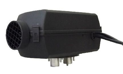
An installation that heats the cab or driver's workplace with the help of warm air flows is called an air heater. The design includes a heating element, a pump for supplying diesel fuel, ballasts and wires for connecting the elements. The devices are produced by the Russian plant Planar (Samara) and are characterized by an affordable price with high efficiency, as evidenced by the reviews. In the photo - a heating car installation.
The principle of operation of the Planar air heater is as follows: the fuel mixture is pumped into the combustion chamber by a pump. The heat generated during combustion is transferred to the heat exchanger. The latter is blown by an air stream, and then the heated air is supplied to the driver's cab. Combustion products are removed from the car interior, therefore it is forbidden to use the Planar heater in enclosed spaces - a garage, a workshop.
The fuel mixture for the device is diesel fuel obtained from the tank. The heater works offline, regardless of the state of the engine.
Each time the heater is turned on, a preliminary test of the overheating sensor, pump status, burner indicator and electrical circuits is carried out. If there is a deviation in the state of the elements according to the instructions, the ignition will not be initiated. If the test is successful, the combustion chamber is pre-purged - the air is removed from the passenger compartment, the candle ignites, and then a mixture of fuel and combustion air is supplied. Upon reaching normal stable combustion, the candle is turned off.
When switched off, the supply of the fuel mixture is stopped, the burner is extinguished and the combustion chamber is purged.
The temperature is adjusted automatically, according to the set value: from 15 to 30 degrees. When the air temperature in the cabin reaches the set value, the device switches to a mode with less heat output. If the difference between the parameters is large, the device may activate the ventilation mode, which helps to cool the workplace. When the air temperature drops, the Planar autonomous heater switches to a more active mode. Optionally, the device can be equipped with a remote temperature sensor, which is located in the cabin
Installation of the installation is carried out only by specialists.
The device works offline - the engine can be turned off.
Reported low fuel consumption. The latter is supplied to the heater from the tank.
The products of combustion are removed from the car interior, providing a clean atmosphere inside.
The device is compact and lightweight - up to 12 kg depending on the model. At the same time, the cabin is heated literally in a matter of minutes. The photo shows a sample.
Affordable cost.
The disadvantages include some limitations in application - the installation cannot be placed in places where dust accumulates or accumulation of vapors of flammable substances is possible, and a battery is also required.
The Planar heater is equipped with several security systems that ensure stable operation of the device and emergency shutdown in case of emergency.
If the launch attempt fails, a second attempt is made by default. If start-up is still impossible, the device switches off.
In the event of a burner malfunction, the device switches off immediately.
It also automatically shuts off when the heat exchanger overheats. When the current decreases or jumps, the unit turns off.
All of the above events are reflected on the remote control by flashing the LED - red or orange, in a certain mode. The instruction contains a decoding of the signals, which allows you to quickly determine the cause of the non-working state, as evidenced by user reviews. In the photo - the control panel.
You can extend the life of an autonomous heater and significantly reduce repair costs by following the rules of use recommended in the instructions.
Fuel - it is known that the efficiency of the engine depends on the ambient temperature. For the Planar heater, it is also recommended to comply with certain conditions. So, at temperatures up to -5 C, diesel fuel 3-0.2 is used, at values from -5 to -20 C, it is desirable to use a mixture of gasoline and diesel fuel, and at lower temperatures - A-0.4 brand fuel.
It is recommended to turn on the heater for 5-10 minutes once a month, even when there is no need to heat the passenger compartment. Thus, the appearance of film deposits in the fuel pump is anticipated.
Do not turn off the device until the end of the purge phase. At any other time, a shutdown is possible.
The charge level of the battery should be checked. If the car is not used for a long time, then the Planar heater must be disconnected from the battery.
Do not connect the heater to the electrical circuit of the machine while the engine is running. The device is powered only from the battery, regardless of the weight of the vehicle.
When refueling the vehicle, the device must be switched off.
Repair of the device is recommended to be entrusted to specialists. However, with simple problems that are not related to the burner and damage to electrical parts, you can handle it yourself, judging by the reviews. The instructions that come with the device describe in detail the most likely of them.
Quite often, if the recommendations for switching to winter fuel are not followed, the fuel filter waxes. As a result, the Planar device does not turn on. In this case, you should first change the fuel to the one corresponding to the weather conditions, and check the operation of the fuel intake. If, after cleaning its filter, the Planar heater still does not work, the fuel supply pump should be dismantled, and, having unscrewed the fitting, remove the filter. The element is washed in gasoline and blown with compressed air, and then installed in place. The fitting at the end of the repair should be fixed on the sealant. The video shows the filter cleaning process in more detail.
prices for spare parts for planar heaters
glow plug for heaters Planar 4dm
glow plug for heaters Planar 44d
Japanese glow plug (GP) for heaters Planar 2d, 44D-GP
glow plug for heaters Planar 8dm
Cabin sensor for Planar heaters
combustion chamber for heaters Planar 2d
combustion chamber for heaters Planar 4dm
combustion chamber for heaters Planara 44d
air blower for heaters Planar 2d, 44d
air blower for heaters Planar 4dm
control unit (brains) for heaters Planar 2d
control unit (brains) for heaters Planar 4dm
control unit (brains) for heaters Planar 44d
metal hose (exhaust) for Planar 1 m (half can be cut off)
fuel pump for heaters Planar 2d, 4dm, 44d
heat exchanger for heaters Planar 2d
heat exchanger for heaters Planar 4dm
heat exchanger for heaters Planar 44d
thermostat for heaters Planar 4dm
temperature sensor for heaters Planar 2d
flame indicator for heaters Planar 4dm, 44d
control panel for heaters Planar 4dm
control panel for heaters Planar 2d, 44d
power supply harness with fuses for Planar heaters
fuel pump harness for heaters Planar 4dm, 44d
inlet casing for heaters Planar 4dm
outlet casing for heaters Planar 4dm
upper casing for heaters Planar 44d
lower casing for heaters Planar 44d
inlet grille for heaters Planar 44d
outlet grille for heaters Planar 44d
fuel intake for heaters Planar 44d
transparent fuel tank 7.5 liters for Planar heaters
fuel pipe for Binar and Planar (you can cut off half)
Air duct ( Ф 60x t 150 C)
Tee T – figurative 90° 75*75*75
Tee T figurative 90 ° 60*60*60
Tee Y - shaped 120 ° 75*75*75
Thermal insulation for the exhaust pipe (sleeve 28x5x450)
Grille (blinds not rotary) Ф 75 mm
Adapter for PLANAR 4DM, 4DM-2 for air duct (90x75)
Video (click to play).
Adapter for PLANAR 44D for air duct (96x75)