
In detail: do-it-yourself power supply unit for repairing mobile phones from a real master for the site my.housecope.com.
In most cases, cell phone breakdowns are quite easy to fix and boil down to replacing the display, speaker, all kinds of cables and body elements. In the overwhelming majority of cases, complex soldering of any elements is not required. The repair process is limited to replacing the display or ribbon cable, which is connected to the printed circuit board of the cell phone through a connector. It is also quite often required to clean the printed circuit board of a cell phone from corrosion and oxides. In this case, time-consuming soldering of microcircuits and other elements is not required.
But there are breakdowns in which it is necessary to replace any microcircuit or to solder some element on the printed circuit board of the cell phone (SIM card holder, battery connector, power connector, etc.).
To successfully repair cell phones, a special tool is naturally required. In addition, consumables are also needed, which should be on hand during the repair process.
When equipping one workplace for the service repair of cell phones, several devices will be needed. Let's list them. We will not consider the devices required for software repair of cell phones.

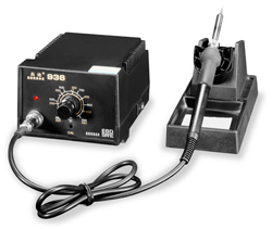 For professional cell phone repair, of course, you need to get a soldering station. All radioelements on a cell phone board are surface-mounted, and radioelements are extremely small in size. When soldering such tiny (SMD) elements, the soldering temperature should be monitored and care should be taken not to overheat the electronic components. The soldering temperature of electronic components should not exceed 240 0-260 0 C. If the critical temperature is exceeded, the probability of damage to the electronic component is high.
The soldering station has all the necessary functions for working with small-sized parts. This is the regulation of the temperature of the soldering iron tip within 200 0 - 480 0 C, digital indication of the temperature of the tip, the ability to use all kinds of tips for any work. It is also worth noting that a conventional electric soldering iron is not galvanically isolated from the mains, which increases the likelihood of damage to sensitive electronic elements on the mobile phone board. Therefore, an ordinary electric soldering iron is not suitable for repairing cell phones.
| Video (click to play). |
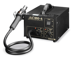 There are two approaches to soldering surface mount elements (SMD, BGA). The first is soldering with a jet of hot air and the second is infrared soldering. Despite the fact that soldering with infrared (IR) radiation has a lot of advantages over hot air soldering, it is hot air soldering stations that are more widely available on the market. This is probably due to the fact that they have a simpler design and are several times cheaper than infrared soldering stations. It should also be noted that infrared soldering stations are more suitable for repairing motherboards of laptops and computers with large sizes.
In the motherboards of computers and laptops, microcircuits are used that have larger linear dimensions than the microcircuits on the board of cell phones, and during dismantling, an even and larger heating of the microcircuits is needed. Infrared soldering stations just have such qualities as uniform heating.
Unlike infrared soldering stations, hot air soldering stations heat up the element to be soldered less evenly.In addition, when working with a hot air soldering station, it is necessary to monitor the speed of the hot air flow. If the air flow rate is set too high, then during soldering it is easy to “blow off” adjacent elements and the heating of the element will be uneven due to the presence of swirls of hot air. If you reduce the air flow rate, then the heating of the brazed part will be slower due to the fact that the still air is a heat insulator.
Despite the negative qualities of hot air soldering, hot air soldering stations are actively used in the repair of cell phones. The small dimensions of printed circuit boards of cell phones and electronic components on them allow for a sufficiently high quality installation and dismantling of microcircuits and small-sized elements. Of course, during the repair process, it is worthwhile to correctly set the rate of hot air supply through the nozzle of the hair dryer and the temperature of heating the air.
 Why do you need device for bottom heating of boards? Oddly enough, but when repairing portable electronics - laptops, mobile phones, PDA - the device is very necessary. Here's the thing.
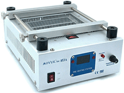
If it is necessary to dismantle any part from the printed circuit board of the device, it is necessary to heat the element to the reflow temperature of the solder. Since SMT elements and BGA microcircuits are very widely used in portable electronics, when soldering with hot air, you have to warm up the microcircuit case first, and only then the contacts themselves. Naturally, heat transfer occurs from the heated microcircuit to the printed circuit board. This leads to the fact that it is necessary to heat up the element to be brazed for a long time, which can lead to its overheating.
In addition to overheating of electronic components, there is also the possibility of damage to the printed circuit board. With uneven heating, it begins to warp, deformation, delamination occurs. If the printed circuit board is suddenly heated to a temperature of more than 280 ° C, then it will swell. In the future, it will not be possible to eliminate this deformation of the printed circuit board. For smooth and uniform heating of the printed circuit board, the bottom heating station is used.
When replacing such elements as, for example, the SIM-card holder, the bottom heating of the board is very convenient. Before soldering the faulty latch, the printed circuit board is heated with the help of the bottom heating station of the boards to a temperature of 120 0 - 140 0 C. In this case, the solder at the soldering point of the contacts heats up and for its final reflow, short-term hot air soldering using a hot air gun is required. If you solder the retainer only with a hot air soldering station, prolonged exposure to hot air will deform the plastic base of the SIM card retainer. It is clear that when replacing the joysticks, the bottom heating station will also facilitate the work and will allow it to be performed more efficiently.
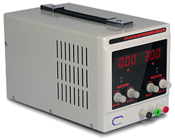 When restoring cell phones, you will definitely need power unit... It can be used to charge a discharged mobile phone battery or power a repaired device. In some cases, during repairs, it is necessary to control the current consumed by the cell phone. Therefore, it is desirable that a built-in ammeter is present in the power supply. Preference should be given to devices with a dial-up ammeter, since ammeters with digital indication are more inert.
For convenience, you can use a normal serviceable battery from any cell phone. Conductors with crocodile clips are soldered to its conclusions (there are three of them). This universal rechargeable battery can be used to repair any cell phone. The main thing is to be able to correctly connect the clamps to the power connector of the repaired cell phone and from time to time to charge such a universal rechargeable battery.
In many cases, the universal battery is sufficient to diagnose a cell phone malfunction and check if it is working properly. In this case, a stationary power supply may not be required at all.
 It's no secret that one of the most common causes of mobile phone malfunctions is exposure to water. Since the cell phone is constantly switched on and has an autonomous power supply, traces of electrochemical corrosion appear on the metal surfaces and contacts of the printed circuit board even if it gets into water for a short time. The complexity of restoring the operation of phones - "drowned" is that the printed circuit board of the mobile phone is multilayer, and many microcircuits are mounted on the board using the BGA method, which makes it difficult to clean the contacts located under the microcircuit case. Manual cleaning of the printed circuit board with special cleaning sprays or alcohol does not always lead to success, and the cell phone does not always restore its functionality.
For deeper cleaning from corrosion and restoration of telephone boards - "drowned" ultrasonic baths (RAS). The cleaning agent is poured into the ultrasonic bath. Under the action of ultrasonic waves, microbubbles appear in the liquid, which collapse and move randomly, effectively cleaning all elements damaged by corrosion. Ultrasound speeds up chemical and physical processes, and the use of a special cleaning fluid promotes high-quality cleaning. With the help of an ultrasonic bath, it is possible to restore the operation of a seemingly hopeless cell phone.
Multimeter in the workshop - this is already a classic. Any master who repairs electronics always has a multifunctional tester in his workshop, with which you can measure voltage, current, resistance, and carry out a "continuity" of contacts. And if the multimeter also has a thermocouple, then it can measure the temperature of the printed circuit board or electronic component during repair work.
This is just an approximate answer to the question of what equipment you need to have in a workshop to repair cell phones. Many of the listed devices will not be required immediately, but as professional growth and development of your business. It is also worth noting that the devices required for software repair are not considered here.
Do not forget that in the process of hardware repair, consumables are needed: flux, solder paste, cleaner, etc.
To begin with, it is strongly recommended that you familiarize yourself with at least the basics of radio electronics. The fact is that the repair of mobile phones is closely related to theoretical knowledge in this area. For example, if you need to replace a resistor (this is a passive current-limiting radio electronic component), then you definitely need to know its labeling, resistance, power dissipation, temperature coefficient, etc. With other owls, it is not very advisable to repair mobile phones without knowing Ohm's law. There are a huge number of books and manuals on the topic of radio electronics, as well as thematic sites on the Internet. But this is not enough. Mobile phones are digital devices, not analog ones. Consequently, all parts and components used for the production of the latter have differences among themselves. For example, for analog devices, surface mounting technology is mainly used, and for digital devices, surface mounting. The latest technology is called SMT (surface mount technology). It also translates as "surface mount technology". And the components used in this technology are called SMD (surface mount device).
Also, there is no analog signal in digital electronics, because it is actually digital. Consequently, all digital devices have their own types and levels of programming. These are just a few of the differences between analog and digital technology. But even this is enough to scare a newbie away.But there is no need to despair here. Everything is much easier than it seems. A lot of that frightening information is not needed when repairing mobile devices. But if you are planning to seriously tackle this business, then it is strongly recommended to study analog and digital radio electronics.
Now we come to the main goal of this article. So, now you will be described in detail the procedures for technical repair of mobile phones and types of repair devices.
In order to repair a cell phone, including repairing Nokia, Samsung, Sony-Ericsson, LG, Motorola, the first thing is to determine the cause of the failure of the mobile device and identify the component, assembly, module or part that has failed. For this, the knowledge that is described above is just needed. Usually, the breakdown of a mobile phone is caused by improper operation or loss of functionality of external devices. For example, in the first case, the phone fell into the water by negligence. To restore it, complete disassembly and thorough drying are required. After that, you need to use a soft-bristled brush to clean the phone's printed circuit board with a special cleaning agent or 96% alcohol solution. In the second case, the LCD, speaker, microphone, keyboard, etc. are out of order. As a rule, in most cases, such parts cannot be repaired and must be replaced. But if there was damage to the surface (soldered) parts on the printed circuit board, then a professional approach and experience are required. In addition, for this type of repair, you will need a diagram of assemblies, modules and components of the printed circuit board of a mobile phone.
In order to start the repair procedure, the phone must be disassembled.
To open a mobile phone without causing cosmetic damage to it, you need to acquire special tools for opening them. They allow you to open the phone case accurately and as efficiently as possible without causing defects. As a rule, these instruments are sold in sets, each item of which is responsible for its own specific opening. Such kits are not difficult to find in specialized stores. In addition, they come in various types. The difference is the functionality and the price.
You also need a specialized set of screwdrivers for mobile phones. You don't need to save on this. The more specific number of attachments you have, the more chances you will have to unscrew the screws without breaking the edges.
Further, in order to diagnose the phone for its malfunction, you will need a good digital multimeter. It can be used to measure AC and DC voltage and current, resistance, capacitance of capacitors, coefficient of transistors, diode state, continuity of circuits, sections of circuits or nodes, temperature. With skillful use and knowledge of some physical laws, they can find faults in the circuit. The range of multimeters is enormous. The difference is usually in functionality and price.
We also need a laboratory power supply or power supply. With it, it will be possible to set the specified voltage and current. You will need it very often when carrying out repair work, because it will be inconvenient to substitute the rechargeable battery for testing, over and over again. Modern power supplies are equipped with current stabilization and protection functions, as well as a large number of all kinds of clamps and probes for various cases.
Soldering equipment and fixtures. To carry out soldering work, you need a soldering station. Their variety is infinitely large, and the choice is determined by the price and functional range. There are combined soldering stations that combine both a heating soldering iron with temperature control and a hot air dryer, which also has the function of adjusting temperature and air flow.
A hot air dryer is usually required for mounting and dismounting SMD components, as well as integrated circuits made in a BGA package.
Also, when carrying out soldering work, you will need a device for the bottom heating of printed circuit boards. The fact is that when installing or dismantling, for example, integrated circuits (chips), there is a risk of overheating and failure. When using a heating device, on which the printed circuit board of the mobile phone is placed and fixed, the board is rationally heated. And already when the board is heated, you can start assembling or disassembling components without fear of their breakage. this procedure takes place in a few seconds.
Antistatic thermo-tweezers are also useful for soldering work. It is very convenient to use it to dismantle some of the components.
Since you will be faced with soldering work on the installation / dismantling of integrated circuits, you will need a vacuum manipulator. This device is manual and automatic. It is designed to place the chips with the contact pins on the surface of the printed circuit board of the mobile device as accurately, efficiently and conveniently as possible. It is inconvenient to do this with tweezers, especially since there is a high probability of “kill” the microcircuit with an uncalculated pressure. This will never happen with a vacuum manipulator.
Also in the work you need a desoldering pump. With the help of it, you can easily perform soldering by removing the molten solder.
Optics. Parts and components of mobile phones are measured in micrometers and nanometers. It is clear that working without special magnifying devices is very problematic and harmful to vision. In these cases, it is strongly recommended to acquire a 40 diopter technical microscope (not to be confused with a biological one). You will also need a backlit tabletop magnifier. It is not convenient to work with a microscope in all cases, and a desktop magnifier is convenient to use almost always when ultra-high magnification is not required. Mounting magnifying glasses or forehead binocular glasses also do not hurt.
To carry out washing, cleaning all kinds of components and printed circuit boards from dirt, oils, fats, solder, plaque and rosin, you need an ultrasonic bath. It performs ultrasonic cleaning very efficiently and safely.
Other tool. Among other installation tools and accessories, you will need a mounting fixing table, with which you can easily and securely fix the printed circuit board for repair work. Be sure to have a variety of tweezers, mounting awls, round-nose pliers, pliers, long-nose pliers, wire cutters with you. You can add solder paste, flux, solder, rosin, cleaners, ultrasonic cleaner and other consumables to this list.
Where to get parts and components for repair? Of course, you can buy them in specialized stores, but it is best to buy broken phones. Since in some cases, it will be very problematic to find some parts, and it will not be difficult to buy, for example, a broken phone, which contains the necessary part, moreover, at a very low price.
Well, here we are with you and got acquainted with the minimum that a mobile device repair engineer should have. Of course, knowledge and experience will come with time, as theoretical and practical skills are developed. Read books on electronics, if possible, sign up for special training courses in the repair of mobile phones, communicate with people who have experience in this area, visit specialized forums on specific topics, where people are always ready to help.
In general, great success to you in your mobile phone repair business!
More information for learning self-repair of mobile phones HERE.
This article was born due to the fact that I had to deal with the frequent repair of cell phone chargers. Even though the price of a Chinese charger does not exceed 100 rubles (new), they bring them to me regularly. And for all their uniformity, there are slight differences in the construction of the charger schematic.
This material will combine the chargers that I copied myself and found on the Internet.
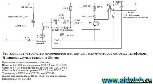
LG phone charger circuit
Another version of the charger is the so-called Frog
Let's go further
Well, and lastly, the scheme for obtaining from 12-24V at the output of 4.5V 0.8A. Car adapter Panasonic Pulse, stabilized on 4 transistors.
Greetings radio amateurs.
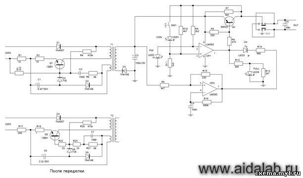
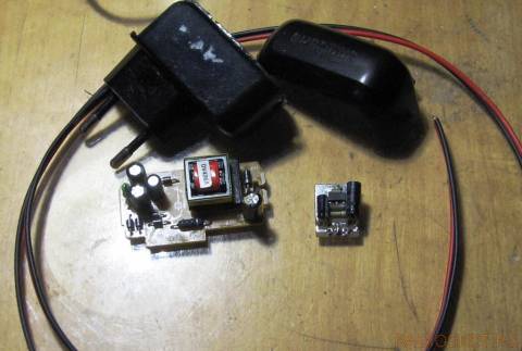
Going through old boards, I came across a couple of switching power supplies from mobile phones and wanted to restore them and at the same time tell you about their most frequent breakdowns and elimination of shortcomings. The photo shows two universal schemes of such charges, which are most often found:
In my case, the board was similar to the first circuit, but without an LED at the output, which only plays the role of an indicator of the presence of voltage at the output of the block. First of all, you need to deal with the breakdown, below in the photo I outline the details which most often fail:
And we will check all the necessary details using a conventional DT9208A multimeter.
It has everything you need for this. Continuity mode for diodes and transistor transitions, as well as an ohmmeter and capacitor capacitance meter up to 200μF. This set of functions is more than enough.
When checking radio components, you need to know the base of all parts of transistors and diodes, especially:
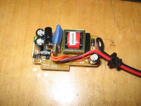
Now we are completely ready to check and repair the switching power supply unit. Let's start checking the unit to identify visible damage, in my case there were two burnt resistors with cracks on the case. I did not reveal any more obvious shortcomings; in other power supplies I met swollen capacitors, which also need to be paid attention to in the first place. Some details can be checked without soldering, but if in doubt, it is better to unsolder and check separately from the circuit. Solder carefully so as not to damage the tracks. It is convenient to use a third hand during the soldering process:
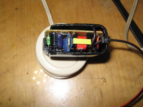
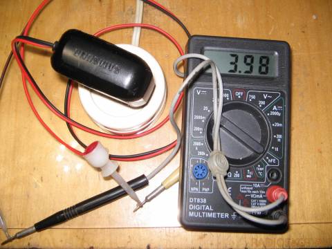
After checking and replacing all faulty parts, do the first turn on through a light bulb, I made a special stand for this:
We turn on the charger through the light bulb, if everything works, then we twist it into the case and rejoice at the work done, if we are not looking for other shortcomings, also after soldering, do not forget to wash off the flux, for example, with alcohol. If all else fails and nerves are in the balance, discard the board or solder and select live parts in stock. Everyone is in a good mood. I also suggest watching the video.
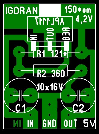
In a radio facility, a simple power supply from a suitable charger, with an output of 6-8V 0.5-0.7A, may come in handy for checking or repairing a cell phone. To do this, we need a suitable charger from a cell phone and an LM1117 stabilizer, or the like. You can find these stabilizers on motherboards, video cards and various Chinese devices. And the boards themselves can be got hold of in computer repair shops, where they are simply thrown away.
Earlier, I have already laid out a similar alteration of the memory, you can see it here:
https://my.housecope.com/wp-content/uploads/ext/2533/forum/3-3792-2 post 16.
On a miniature seal, we assemble a voltage stabilizer and adjust the 4V output with a resistor R1.
If space permits in the memory, you can solder a small heat sink, it will not hurt. Then we embed the scarf in any free space in the memory, and for greater safety it can be shrink-wrapped.
We remove the old cord and, drilling through the adapter block, insert a suitable one with thicker wires. We solder mini crocodiles or mini clips like mine, if any, to them.
As a result, we get a simple power supply unit for testing or repairing cell phones.Moreover, the unit can be useful for the initial charge of completely dead lithium batteries (their rise), for the subsequent full charge. For this, a small heat sink is useful in the block, because the stabilizer in this application will warm up a little.
Good luck with the renovation .. 
Somehow I decided to create a normal power supply,
I shoveled the entire archive of Radio magazines, but I could not find the scheme I needed,
either the element base did not fit, or the circuits were very cumbersome and did not meet the requirements.
And now, a miracle, I came across this scheme and picked up parts that were more or less suitable for the characteristics of the parts used in the scheme.
VT1-kt315, vt2-kt801, vt3-kt361, vt4-kt805 (these were previously used in the output stage of the frame scan of 3USTS TVs)
we sculpt it on the radiator. I made a rectifier using a bridge circuit with 1n4007 diodes, an electrolyte at 4700 μF and a film at 0.1 μF.
The device does not need to be configured and, with correct installation and assembly, starts working immediately. It works for me in the range from 0 to 15 volts.
P.S. Gentlemen, sorry for the photo, I whipped it up with a mobile)))
And which box to fill in SAMSUNG GDFS from NOKIA


There is a special BUTTON for thank you
UFS, RIFF-box, SeTool, Mx-box, ATF, Z3X-box.
Voltage from 1.7 volts to 15 volts smoothly, with current stabilization 0-1.2A, adjustable or 1A fixed.
The voltage is automatically set to the desired value when the connector is plugged into the power supply (we prepare a set of cords with connectors from different phones, plugged in, the power supply itself set the required voltage). Two-stage protection, stabilization of the current at the set value and opening the circuit when the voltage in the channel drops below 1.5 volts (such a drop indicates that either the polarity is reversed or the semiconductor in the supplied circuit is knocked out or a short circuit in the terminals). Open circuit protection works as follows. After the protection is triggered, the unit lights up the alarm LED, beeps briefly, waits for 10 seconds and then breaks the circuit and goes into the standby mode for manual reset of the protection. Return to work after pressing the reset button.
There is also a sound signaling of the current stabilization actuation (both the beginning and the end), short “ticks” of different tonality for both cases.
Ammeter for two ranges, 600mA and 1.2A, with automatic range selection.
The general voltmeter is the one in the photo above (in the second photo, the switch for selecting the voltmeter measurement channel is visible on top of the voltmeter head).
I also made an external block for using the channel as a laboratory one. It has ordinary terminals, alternators for adjusting current, voltage and a pair of toggle switches (voltage is fixed at five volts and adjustable and switching of the transformer windings for voltages at the channel output up to seven volts and up to fifteen).
Adjustable, with step voltage change. Values are 2.8V, 3V, and 3.6 to 4.3V in 0.1 Volt steps. Open circuit protection with thresholds of 0.5A and 1.2A with rated response times. In fact, when the mobile phone is operating, the protection does not work in the transmission mode, even if the protection is squeezed to a threshold of 200 mA. In this case, an error with an inverted polarity does not lead to fatal consequences, because the protection is triggered faster than the capacitor charges “crookedly” by Vbat to a voltage of one volt.
The protection logic is simple, when the protection current exceeds the set threshold, it breaks the circuit. An audible signal sounds, the LED flashes. After five seconds, the protection is reset. If the protection was triggered three times in a row, the attempts are stopped. Disconnection from the state with the red button. When the protection is not activated, pressing and holding the same button (for about two seconds) leads to an open circuit for five seconds.
The current indicator is a pointer, with the limits of 100mA, 500mA and 1A, with automatic range selection and a dynamic LED (visible on the head of the voltmeter to the right of the display). Dynamic easily allows you to visually observe the dynamics of current consumption during the phone's operation (you can see how the processor reads blocks from the flash or jerks devices on the I2C bus when turned on.
The view turned out to be of course neat, the body is small, it was not possible to logically arrange all the controls. Although it is convenient to use. And it takes up little space on the table.
I will not give a diagram. for it is a third stage obese arctic fox. I can only say that the density and quantity of the contents turned out to be such that a box of 130-190-60 size turned out to weigh almost three kilograms. And you can't push your finger inside.
If it is multiple, the stabilizer is made on AZ1084ADJ (LM317 type but with low voltage drop) with TL431 support (gives good voltage stability in time and temperature). The rest is op-amp OP07 as a current sensor amplifier, UD6 in the current stabilizer and several LM324 as terminals and comparators. And a bunch of 74 logic to ensure the protection work, because I had to look for a programmer from microcontrollers in scrap. In general, nothing that would not be found in the IS of Hill and Horowitz.
Perhaps the most "sick" part of a cell phone is its charger. A compact DC power supply with an unstable voltage of 5-6V often fails for various reasons, from the actual malfunction to mechanical failure as a result of careless handling.

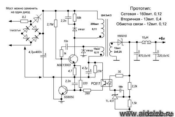
However, it is very easy to find a replacement for a faulty charger. As the analysis of several chargers from various manufacturers has shown, they are all built according to very similar schemes. In practice, this is a circuit of a high-voltage block-king generator, the voltage from the secondary winding of the transformer of which is rectified and serves to charge the cell phone battery. The difference usually lies only in the connectors, as well as non-fundamental differences in the circuit, such as the implementation of the input network rectifier in a half-wave or bridge circuit, the difference in the setting of the operating point based on the transistor, the presence or absence of an indicator LED, and others. little things.
So, what are the "typical" malfunctions? First of all, you should pay attention to the capacitors. A breakdown of the capacitor connected after the mains rectifier is very likely, and leads both to damage to the rectifier and to the burnout of a low-resistance constant resistor connected between the rectifier and the negative plate of this capacitor. This resistor, by the way, works almost like a fuse.
Often the transistor itself fails. Usually there is a high voltage power transistor marked "13001" or "13003". As practice shows, in the absence of such a replacement, you can use the domestic KT940A, which was widely used in the output stages of video amplifiers of old domestic TVs.
Breakdown of the 22 μF capacitor leads to the lack of generation start. And damage to the 6.2V zener diode leads to an unpredictable output voltage and even failure of the transistor due to overvoltage at the base.
Damage to the capacitor downstream of the secondary rectifier is the least common.
The design of the charger body is non-separable. You need to saw, break: and then somehow glue it all together, wrap it up with electrical tape. The question arises as to the expediency of the repair. After all, to charge a cell phone battery, almost any constant current source with a voltage of 5-6V, with a maximum current of at least 300mA, is enough. Take such a power source, and connect it to the cable from the faulty charger through a 10-20 ohm resistor. And that's all. The main thing is not to mix up the polarity. If the connector is USB or universal 4-pin - between the middle contacts, include a resistance of about 10-100 kilo-ohms (select so that the phone "recognizes" the charger).
The article describes a typical malfunction of mobile phone chargers.A diagram of one of such blocks is given, drawn up according to a "live" sample, recommendations are given on changing the output parameters and using the repaired block in amateur radio practice.
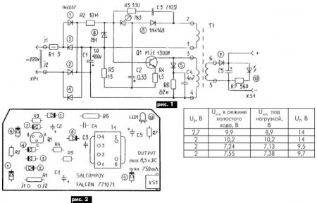
The fault was the zener diode, conventionally designated in the diagram in Fig. 1 by number 7. It had a leak and "floating" parameters.
The free space in the case of the power supply made it possible to use a chain of several series-connected domestic zener diodes instead. At the same time, it was easy to obtain other, in addition to the passport, output voltage values (see table).
This will probably be of interest to radio amateurs, since they will always find use for such a powerful and small-sized power supply. The layout of the elements on the board is shown in Fig. 2.

The diagram below for MC34063A allows you to charge your iPod without connecting to a computer. Using a computer's USB port to charge the battery is not always practical. For example, there is no computer at hand or there is no need to turn it on because of charging. Mobile phone chargers, iPods and MP3 players are available, but they are expensive and need to have separate charging options for home and car charging.
On a long hike (hiking or cycling), lighting is indispensable. There are not enough flashlights, which are recharged from the mains, for a long time, and tourist routes pass mainly in places where there are no power lines. The "Tourist" charger will help to solve this problem. More details ...
I wanted to collect some kind of battery charger. And the very first thing that I thought to collect was protection against polarity reversal on the relay. The following simple circuit for protecting the charger and battery is within the power of anyone, even a novice radio amateur. More details ...
Fuel-free generator - mobile phone charger.
A short description for the video, which demonstrates the operation of a fuel cell powered by ethyl alcohol.
The article describes the design of a simple triac power regulator for controlling incandescent and LED lamps, designed to be controlled using dimmers. It also tells about the experience of repairing factory dimmers manufactured by Leviton.
This article describes the design of a homemade portable charger designed to power or charge batteries for USB-compatible players, mobile phones and smartphones.
The difference between this power supply unit and similar ones is that it controls its own switching on and off, both in the mode of charging its own batteries, and in the mode of energy release.
Sources of cheap lithium-ion batteries and how to disassemble a laptop battery for repairs or to remove batteries when reused.
I have long dreamed of making a battery for my M890C + and DT-830B multimeters from an ordinary 9 Volt battery of the "Krona" type. And now, finally, the turn came to this homemade product.
This article is about how to turn a Krona battery into a battery using as few parts as possible.
This article is about how to assemble the simplest power regulator for a soldering iron or other similar load. https://my.housecope.com/wp-content/uploads/ext/1284/
The circuit of such a regulator can be placed in a power plug or in a case from a burnt out or unnecessary small-sized power supply. It will take an hour or two to assemble the device.
This article describes how to calculate and wind a pulse transformer for a homemade half-bridge power supply that can be made from the electronic ballast of a burnt out compact fluorescent light bulb.
It's about "lazy winding". This is when you are too lazy to count turns. https://my.housecope.com/wp-content/uploads/ext/1284/
In this article you will find a detailed description of the manufacturing process of switching power supplies of different powers based on electronic ballast of a compact fluorescent lamp.
You can make a 5 ... 20 Watt switching power supply in less than an hour. It will take several hours to make a 100-watt power supply. https://my.housecope.com/wp-content/uploads/ext/1284/
Building a power supply won't be much more difficult than reading this article.And for sure, it will be easier than finding a low-frequency transformer of suitable power and rewinding its secondary windings to suit your needs.
This publication continues the series of articles devoted to the construction of an amateur low frequency amplifier.
This article describes the design of a power supply assembled from available parts and designed to power a 10-watt stereo amplifier per channel.
Articles are written as a particular block is made. https://my.housecope.com/wp-content/uploads/ext/1284/
| Video (click to play). |
The next step is the block of regulators and the block of the final amplifier.


