In detail: a power supply unit for repairing phones with your own hands from a real master for the site my.housecope.com.
Greetings radio amateurs.
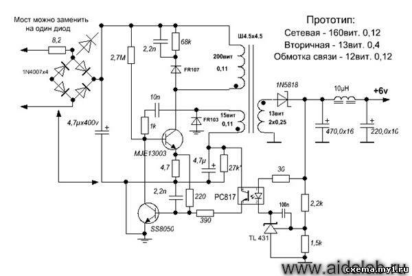
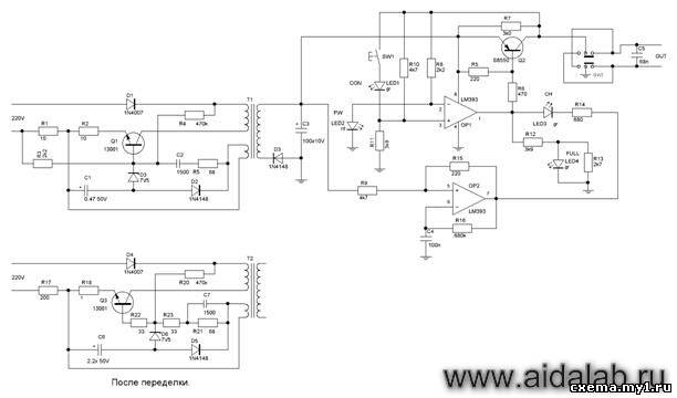
Going through old boards I came across a couple of switching power supplies from mobile phones and wanted to restore them and at the same time tell you about their most frequent breakdowns and elimination of shortcomings. The photo shows two universal schemes of such charges, which are most often found:
In my case, the board was similar to the first circuit, but without an LED at the output, which only plays the role of an indicator of the presence of voltage at the output of the block. First of all, you need to deal with the breakdown, below in the photo I outline the details which most often fail:
And we will check all the necessary details using a conventional DT9208A multimeter.
It has everything you need for this. Continuity mode for diodes and transistor transitions, as well as an ohmmeter and capacitor capacitance meter up to 200μF. This set of functions is more than enough.
When checking radio components, you need to know the base of all parts of transistors and diodes, especially:
Now we are completely ready to check and repair the switching power supply unit. Let's start checking the unit to identify visible damage, in my case there were two burnt resistors with cracks on the case. I did not reveal any more obvious shortcomings; in other power supplies I met swollen capacitors, which also need to be paid attention to in the first place. Some details can be checked without soldering, but if in doubt, it is better to unsolder and check separately from the circuit. Solder carefully so as not to damage the tracks. It is convenient to use a third hand during the soldering process:
| Video (click to play). |
After checking and replacing all faulty parts, do the first turn on through a light bulb, I made a special stand for this:
We turn on the charger through the light bulb, if everything works, then we twist it into the case and rejoice at the work done, if we are not looking for other disadvantages, also after soldering, do not forget to wash off the flux, for example, with alcohol. If all else fails and nerves are in the balance, discard the board or solder and select live parts in stock. Everyone is in a good mood. I also suggest watching the video.
JLCPCB is the largest PCB prototype factory in China. For more than 200,000 customers worldwide, we place over 8,000 online orders for prototypes and small batches of printed circuit boards every day!
This article was born due to the fact that I had to deal with the frequent repair of cell phone chargers. Even though the price of a Chinese charger does not exceed 100 rubles (new), they bring them to me regularly. And for all their uniformity, there are slight differences in the construction of the charger schematic.
This material will combine the chargers that I copied myself and found on the Internet.
LG phone charger circuit
Another version of the charger is the so-called Frog
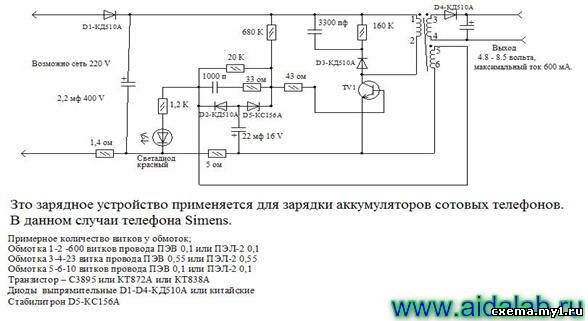
Well, and lastly, the scheme for obtaining from 12-24V at the output of 4.5V 0.8A. Car adapter Panasonic Pulse, stabilized on 4 transistors.
In the radio industry, a simple power supply unit from a suitable charger, with an output of 6-8V 0.5-0.7A, can be useful for checking or repairing a cell phone. To do this, we need a suitable charger from a cell phone and an LM1117 stabilizer, or the like. You can find these stabilizers on motherboards, video cards and various Chinese devices. And the boards themselves can be got hold of in computer repair shops, where they are simply thrown away.
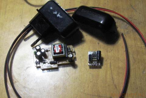
Earlier, I have already laid out a similar alteration of the memory, you can see it here:
https://my.housecope.com/wp-content/uploads/ext/2533/forum/3-3792-2 post 16.
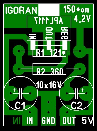
On a miniature seal, we assemble a voltage stabilizer and adjust the 4V output with a resistor R1.
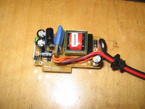
If space permits in the memory, you can solder a small heat sink, it will not hurt. Then we embed the scarf in any free space in the memory, and for greater safety it can be shrink-wrapped.
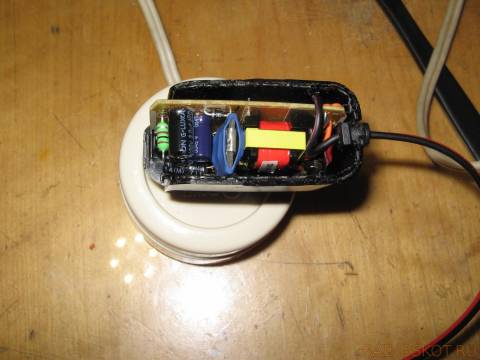
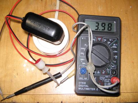
We remove the old cord and, drilling through the adapter block, insert a suitable one with thicker wires. We solder mini crocodiles or mini clips like mine, if any, to them.
As a result, we get a simple power supply unit for testing or repairing cell phones. Moreover, the unit can be useful for the initial charge of completely dead lithium batteries (their rise), for the subsequent full charge. For this, a small heat sink is useful in the block, because the stabilizer in this application will warm up a little.
Good luck with the renovation ..
In most cases, cell phone breakdowns are quite easy to fix and boil down to replacing the display, speaker, all kinds of cables and body elements. In the overwhelming majority of cases, complex soldering of any elements is not required. The repair process is limited to replacing the display or ribbon cable, which is connected to the printed circuit board of the cell phone through a connector. It is also quite often required to clean the printed circuit board of a cell phone from corrosion and oxides. In this case, time-consuming soldering of microcircuits and other elements is not required.
But there are breakdowns in which it is necessary to replace any microcircuit or to solder some element on the printed circuit board of the cell phone (SIM card holder, battery connector, power connector, etc.).
To successfully repair cell phones, a special tool is naturally required. In addition, consumables are also needed, which should be on hand during the repair process.
When equipping one workplace for the service repair of cell phones, several devices will be needed. Let's list them. We will not consider the devices required for software repair of cell phones.
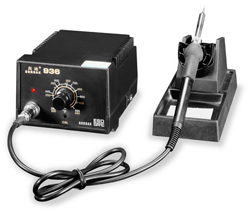

The soldering station has all the necessary functions for working with small-sized parts. This is the regulation of the temperature of the soldering iron tip within 200 0 - 480 0 C, digital indication of the temperature of the tip, the ability to use all kinds of tips for any work. It is also worth noting that a conventional electric soldering iron is not galvanically isolated from the mains, which increases the likelihood of damage to sensitive electronic elements on the mobile phone board. Therefore, an ordinary electric soldering iron is not suitable for repairing cell phones.


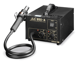

In the motherboards of computers and laptops, microcircuits are used that have larger linear dimensions than the microcircuits on the board of cell phones, and during dismantling, an even and larger heating of the microcircuits is needed. Infrared soldering stations just have such qualities as uniform heating.
Unlike infrared soldering stations, hot air soldering stations heat up the element to be soldered less evenly. In addition, when working with a hot air soldering station, it is necessary to monitor the speed of the hot air flow. If the air flow rate is set too high, then during soldering it is easy to “blow off” adjacent elements and the heating of the element will be uneven due to the presence of swirls of hot air. If you reduce the air flow rate, then the heating of the brazed part will be slower due to the fact that the still air is a heat insulator.
Despite the negative qualities of hot air soldering, hot air soldering stations are actively used in the repair of cell phones. The small dimensions of printed circuit boards of cell phones and electronic components on them allow for a sufficiently high quality installation and dismantling of microcircuits and small-sized elements. Of course, during the repair process, it is worthwhile to correctly set the rate of hot air supply through the nozzle of the hair dryer and the temperature of heating the air.


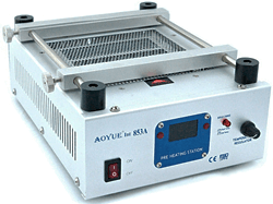

If it is necessary to dismantle any part from the printed circuit board of the device, it is necessary to heat the element to the reflow temperature of the solder. Since SMT elements and BGA microcircuits are very widely used in portable electronics, when soldering with hot air, you have to warm up the microcircuit case first, and only then the contacts themselves. Naturally, heat transfer occurs from the heated microcircuit to the printed circuit board. This leads to the fact that it is necessary to heat up the element to be brazed for a long time, which can lead to its overheating.
In addition to overheating of electronic components, there is also the possibility of damage to the printed circuit board. With uneven heating, it begins to warp, deformation, delamination occurs. If the printed circuit board is suddenly heated to a temperature of more than 280 ° C, then it will swell. In the future, it will not be possible to eliminate this deformation of the printed circuit board. For smooth and uniform heating of the printed circuit board, the bottom heating station is used.
When replacing such elements as, for example, the SIM-card holder, the bottom heating of the board is very convenient. Before soldering the faulty latch, the printed circuit board is heated with the help of the bottom heating station of the boards to a temperature of 120 0 - 140 0 C. In this case, the solder at the soldering point of the contacts heats up and for its final reflow, short-term hot air soldering using a hot air gun is required. If you solder the retainer only with a hot air soldering station, prolonged exposure to hot air will deform the plastic base of the SIM card retainer. It is clear that when replacing the joysticks, the lower heating station will also facilitate the work and will allow it to be performed more efficiently.


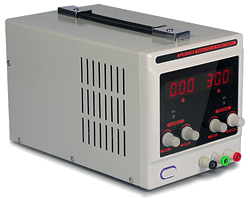

For convenience, you can use a normal serviceable battery from any cell phone.Conductors with crocodile clips are soldered to its conclusions (there are three of them). This universal rechargeable battery can be used to repair any cell phone. The main thing is to be able to correctly connect the clamps to the power connector of the cell phone being repaired and from time to time to charge such a universal rechargeable battery.
In many cases, the universal battery is sufficient to diagnose a cell phone malfunction and check if it is working properly. In this case, a stationary power supply may not be required at all.


For deeper cleaning from corrosion and restoration of telephone boards - "drowned" ultrasonic baths (RAS). The cleaning agent is poured into the ultrasonic bath. Under the action of ultrasonic waves, microbubbles appear in the liquid, which collapse and move randomly, effectively cleaning all elements damaged by corrosion. Ultrasound speeds up chemical and physical processes, and the use of a special cleaning fluid promotes high-quality cleaning. With the help of an ultrasonic bath, it is possible to restore the operation of a seemingly hopeless cell phone.


This is just an approximate answer to the question of what equipment you need to have in a workshop to repair cell phones. Many of the listed devices will not be required immediately, but as professional growth and development of your business. It is also worth noting that the devices required for software repair are not considered here.
Do not forget that in the process of hardware repair, consumables are needed: flux, solder paste, cleaner, etc.
Perhaps the most "sick" part of a cell phone is its charger. A compact DC power supply with an unstable voltage of 5-6V often fails for various reasons, from the actual malfunction to mechanical failure as a result of careless handling.

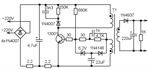
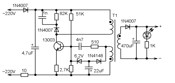

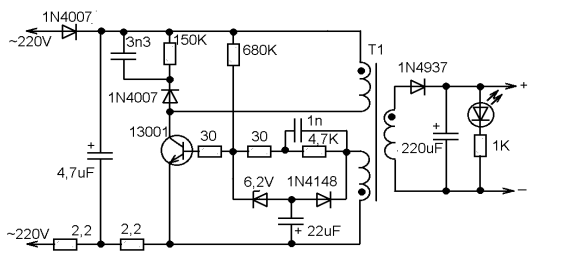

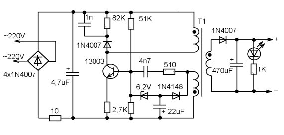
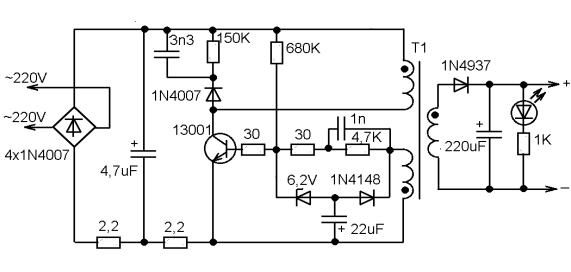

So, what are the "typical" malfunctions? First of all, you should pay attention to the capacitors. A breakdown of the capacitor connected after the mains rectifier is very likely, and leads both to damage to the rectifier and to the burnout of a low-resistance constant resistor connected between the rectifier and the negative plate of this capacitor. This resistor, by the way, works almost like a fuse.
Often the transistor itself fails. Usually there is a high voltage power transistor marked "13001" or "13003". As practice shows, in the absence of such a replacement, you can use the domestic KT940A, which was widely used in the output stages of video amplifiers of old domestic TVs.
Breakdown of the 22 μF capacitor leads to the lack of generation start. And damage to the 6.2V zener diode leads to an unpredictable output voltage and even failure of the transistor due to overvoltage at the base.
Damage to the capacitor downstream of the secondary rectifier is the least common.
The design of the charger body is non-separable. You need to saw, break: and then somehow glue it all together, wrap it up with electrical tape. The question arises as to the expediency of the repair. After all, to charge a cell phone battery, almost any constant current source with a voltage of 5-6V, with a maximum current of at least 300mA, is enough. Take such a power supply and connect it to the cable from the faulty charger through a 10-20 ohm resistor. And that's all. The main thing is not to mix up the polarity. If the connector is USB or a universal 4-pin, connect a resistance of about 10-100 kilohms between the middle contacts (select so that the phone "recognizes" the charger).
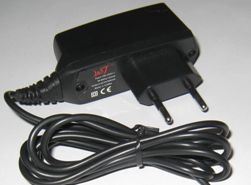
- failure of the charger unit;
- violation of the contact connection of the wire with the plug or charger unit.
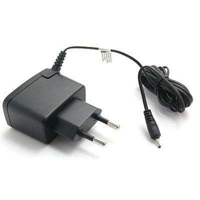
Very often, the reason for the failure of the charger is a wire break or a breakdown in the contact of the wire with the structural elements of the charger - the plug and the block. In this case, you can repair the charger yourself. Let's consider the principle of repairing a damaged charger wire using a specific example of repairing a Nokia mobile phone charger (with a thin plug).
To repair the charger, we need:
- soldering iron and everything you need for soldering;
- insulating tape and heat shrink tubing (if available);
- a small piece of thin wire to make contact with the inner contact part of the charger plug (for Nokia charger slim plug).
The first step is to find a damaged wire or contact connection. Wire damage can be identified visually. The place where the conductive core ruptured, as a rule, is of a different color and slightly smaller in diameter.
If by visual inspection it was not possible to determine the places of damage to the wire, then, most likely, the charger does not work due to the wire breaking off at the point of its connection to the block or plug. The wire may also be damaged, we will find out in the process of further finding the damage.
We take the wire and cut it 7-10 centimeters further than the plug. If there is no breakdown of contact at the point of attachment to the plug, we will connect the wire at the cut. Therefore, you cannot cut the wire at the point of connection to the plug, that is, you must leave a small piece to be able to connect the wires by soldering.
Strip the wires from the part of the wire that goes to the charger. Take a multimeter and select a DC voltage measurement limit of 20 volts.Plug the charger into the network and measure the voltage value at the charger output, that is, at the stripped ends of the cord.
We measure the voltage at the output of the charger
If the device shows a voltage value, then this indicates that the charger unit and the wire are not damaged. In this case, the device showed 7 volts - this is the nominal output voltage of this charger. At this stage, we can conclude that the charger does not work due to a breakdown in the contact of the conductors at the point of their connection to the plug. You can verify this by ringing the plug with the device.
To do this, we strip the wires that go from the plug, insert a thin wire into the inside of the plug (this is necessary for contact with the inner contact part of the plug).
We take a multimeter and select the dialing mode. With one probe, we touch one of the stripped conductors, and with the other, first, to the outer contact part of the plug, and then to the inserted wire. If the device showed contact (the presence of a sound signal), then this indicates that the contact between this wire and the plug is not broken.
We rearrange the probe of the device to another stripped conductor, with the other, alternately touch the outer part of the plug, and then to the wire. If, when both contact parts of the plug are touched, the device does not emit a signal, then there is no contact. That is, one of the wires is torn off the plug.
In this case, there are two ways: you can buy a new plug, or you can repair the old one. The first method is simpler and more reliable. A new plug can be purchased from mobile phone repair shops or the radio market. You may have an old charger that does not have a damaged plug.
In this case, it is enough to solder the new plug to the charger, while observing the polarity. How to check if the wires are connected correctly (polarity)? Typically, each cord has a color-coded wire. If it does not match, then you need to make sure that the wires are connected correctly.
To do this, plug the charger into a wall socket and the new plug into your mobile phone. Connect the conductors of the plug to the charger cord. If charging has started, then you have connected the conductors correctly. If the phone does not charge, swap the conductors. The check must be carried out in any case, even if the color coding of the cords to be connected is the same, since there may be a discrepancy between the cords.
The next step is to solder the two cords together. If you have a heat shrink tubing, place a portion of it over one of the cords to be soldered before soldering. Solder the conductors observing polarity. Insulate both wires with insulating tape, put on heat shrink tubing. Check the charger is working properly.
If you do not have the opportunity to purchase a new plug, and you still want to revive the charger, then the second way to eliminate the damage is suitable for you - repairing the plug.
Remove the rubber (plastic) cover from the plug with a knife. In this case, be careful, do not rush, as you can damage the plug itself.
Remove the rubber cover from the plug
The next step is to solder the charger cable to the plug.
Soldered cord to plug
We check the performance of the charger. If everything is normal, we insulate the conductors and put a heat-shrink tube on the plug. The charger is now ready for use.
Heat shrink tubing on the plug
We examined the case of a broken contact at the point where the cord was connected to the plug. There may be another reason as well. Let's consider one more case.
You cut the wire, checked for the presence of voltage at the output of the charger, it is absent. We cut the wire near the charger, stepping back from the charger block 7-10 cm. We clean the wire that comes out of the charger block and check for the presence of voltage at the output. The presence of voltage at the output indicates that the charger is working properly.We call the plug using the above method. In this case, there is no breakdown of contact.
The dialing of the charger cable showed that one of the conductors was cut off. No damage is visible visually. The best option is to purchase a new wire. Then solder it to the plug and the charger block, observing the polarity.
In order not to be mistaken (especially if the wires have the same color marking), before soldering the wires, connect them and plug the charger plug into the phone. If charging has gone, connect the conductors with soldering. Insulate the wires at the soldering point and put on a heat-shrinkable tube (it must be put on the wire before soldering). The damage has been repaired.
If the wire is intact, the contact connection of the plug is not broken, then the charger unit is damaged or one of the wires inside the unit is torn off.
Unscrew the charger box and look at the wire connections. If all the wires are connected normally, then the charger unit itself is damaged.
If you have a damaged charger unit, then, without having skills in electrical engineering, you will not be able to find the cause of its failure, and even more so to fix it yourself. Repairing your charger from a specialist service will cost you more than a new charger.
The article describes a typical malfunction of mobile phone chargers. A diagram of one of such blocks is given, drawn up according to a "live" sample, recommendations are given on changing the output parameters and using the repaired block in amateur radio practice.
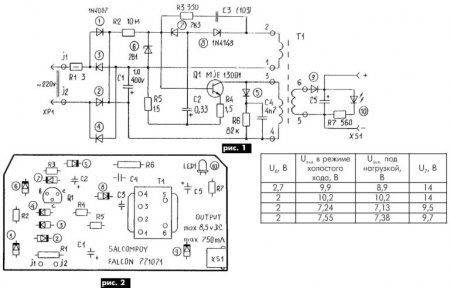
The fault was the zener diode, conventionally designated in the diagram in Fig. 1 by number 7. It had a leak and "floating" parameters.
Free space in the case of the power supply made it possible to use a chain of several series-connected domestic zener diodes instead. At the same time, it was easy to obtain other, in addition to the passport, output voltage values (see table).
This will probably be of interest to radio amateurs, since they will always find use for such a powerful and small-sized power supply. The layout of the elements on the board is shown in Fig. 2.
First, the block needs to be disassembled. Judging by the seams on the case, this unit is not intended for disassembly, therefore, the thing is disposable and in the event of a breakdown, one can not pin high hopes.
I had to literally raskurochit the case of the charger, it consists of two tightly glued parts.
Inside there is a primitive board and a few details. Interestingly, the board is not soldered to the 220V plug, but is attached to it with a pair of pins. In rare cases, these contacts can oxidize and lose contact, and you think that the block has broken. But the thickness of the wires going to the mobile phone connector pleased me pleasantly, you don't often find a normal wire in disposable devices, usually it's so thin that it's scary to even touch it).
There were several details on the back side of the board, the circuit was not so simple, but still it is not so complicated that you would not be able to fix it yourself.
Below in the photo are the contacts of the inside of the case.
There is no step-down transformer in the charger circuit; an ordinary resistor plays its role. Then, as usual, a couple of rectifying diodes, a pair of capacitors for rectifying the current, then a choke and finally a zener diode with a capacitor complete the chain and output the reduced voltage to a wire with a connector to a mobile phone.
The connector has only two pins.
In the event of a breakdown of such a charger, first of all, pay attention to the appearance of the parts, often only by appearance it is possible to determine which part is out of order. Inspect the throttle carefully, it has a very thin wire and it can simply burst. If you cannot identify anything by eye, and you yourself do not understand anything in electronics, ask those in the know to check the details with a tester.If the power supply cannot be repaired at all, then you can assemble your circuit much easier, and if you use a step-down transformer in the circuit, as is done in the branded memory from Nokia mobile phones, then the problems with breakdowns will disappear for a long time. And finally, the easiest way to fix this charger is to buy a new one 🙂
Siemens has chargers with a switching-type power supply, in the article the board is described as a parametric power supply. This is fundamentally wrong. It was not written by a professional. The article price is zero.
charging is original costly the same Chinese 50 rubles and in the purchase 20!
bought a cheap phone buy a cheap charger
I disassemble the glued chargers, power supplies by gently tapping on the body in the places where they are glued with a rubber mallet. The body rests on an anvil.
I completely agree with Alexander about the incorrect description, but the photo of the disassembled charge may be interesting for those who understand.
... as Kuravlyov said in the famous film. "Well, and duraaaak."
It would be nice to write the values \ u200b \ u200bof all resistors or although R13 and R16
Thank you for the article. It is stated in an accessible and understandable way. Repaired charging. It turns out that some piece of iron fell off, I put it in and OK!
As a rule, repairing such an inexpensive device is economically unprofitable.
Especially in non-poor countries. Average price $ 5.
But it happens that there is no extra money, but there is time and spare parts.
No shop nearby. Circumstances do not allow. Then it's not about the price.
In my case, everything was simple - one of my two chargers broke Nokia AC-3E, friends brought a bag of broken chargers. Among them were a dozen branded Nokia chargers. It was a sin not to take it.
The search for a circuit did not lead to anything, so I took a similar one and remade it for AC-3E. A lot of chargers for mobile phones are made according to a similar scheme. As a rule, the difference is insignificant. Sometimes the denominations are changed, a little more or a little less elements, sometimes a charge indication is added. Basically the same thing.
Therefore, this description and diagram are useful for repairing not only AC-3E.
The repair instructions are simple and written for non-specialists.
The scheme is clickable and of good quality.
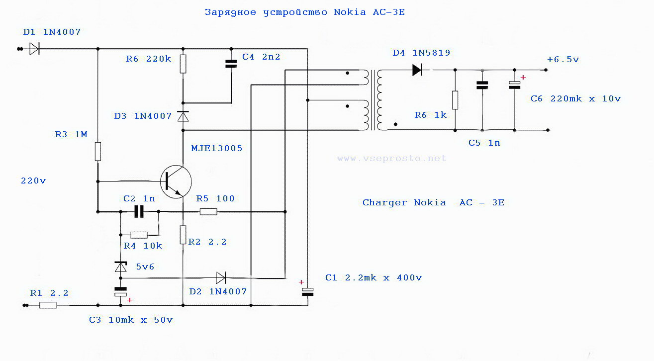
The device is a blocking generator operating in a self-oscillating mode. It is powered by a half-wave rectifier (D1, C1) with a voltage of approximately +300 V. Resistor R1, R2 limits the inrush current of the device and acts as a fuse. The blocking generator is based on a transistor MJE13005 and a pulse transformer. A necessary element of the blocking generator is a positive feedback circuit formed by winding 2 of the transformer, elements R5, R4 C2.
The 5v6 zener diode limits the voltage at the base of the MJE13005 transistor to within five volts.
Damping chain D3, C4, R6 limit voltage surges on the winding 1 of the transformer. At the moment when the transistor is turned off, these surges can exceed the supply voltage by several times, therefore, the minimum allowable voltage of the capacitor C4 and diode D3 must be at least 1 kV.
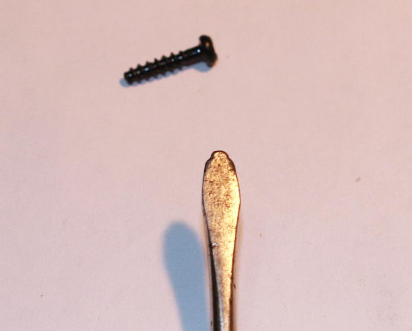
1. Disassembly. The self-tapping screws holding the charger cover in this device look like a triangular asterisk. As a rule, there is no special screwdriver at hand, so you have to get out as best you can. I unscrewed it with a screwdriver, which during the operation itself sharpened under all sorts of crosses.
Sometimes the chargers are assembled without bolts. In this case, the halves of the body are glued together. This speaks of the low cost and quality of the device. Disassembling such a memory is a little more difficult. It is necessary to crack the case with a mild screwdriver, gently pressing on the joint of the halves.
2. External examination of the board. More than 50% of defects can be detected precisely by external examination. Burnt resistors, a darkened board will show you the location of the defect. A burst case, cracks on the board will indicate that the device has been dropped.Chargers are operated in extreme conditions, so falling from everywhere is a frequent cause of failure.
Five out of a dozen memory devices that I happened to do were trite pins bent through which 220 volts are fed to the board.
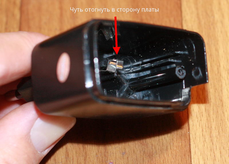
To fix it, just bend the contacts slightly towards the board.
To check whether the contacts are to blame or not, you can solder the power cord to the board, and measure the voltage at the output - the red and black wires.
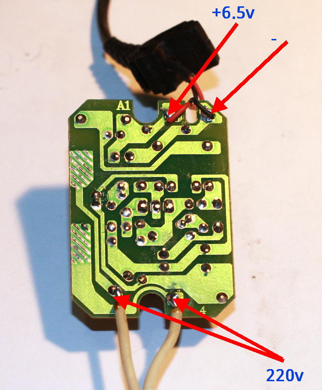
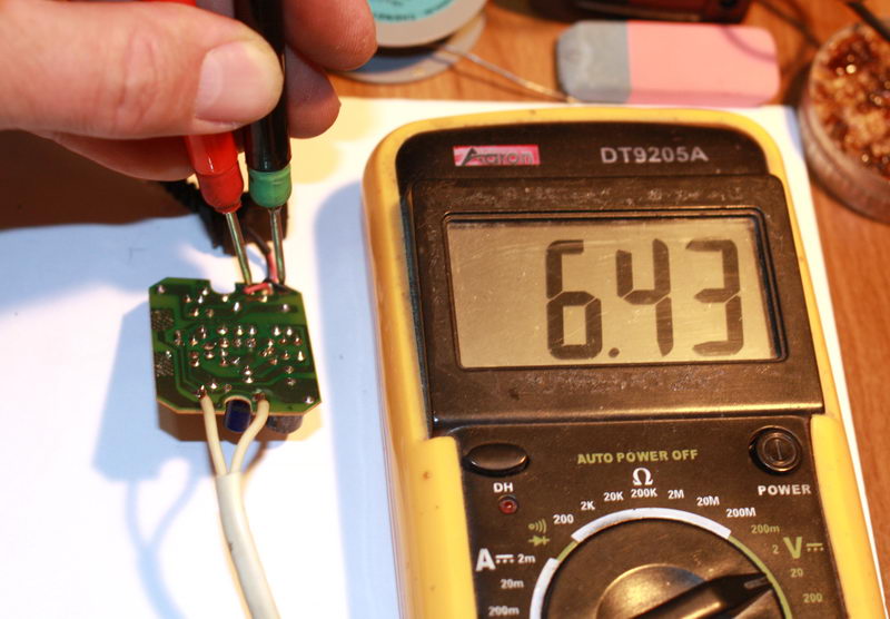
3. Broken cord at the charger outlet. It usually breaks at the plug itself or at the base of the charger. Especially for those who like to talk while charging the phone.
It is called by the device. Insert the pin of the thin part into the center of the connector and measure the resistance of the wires.
4. Transistor + resistors. If there is no visible damage, first of all, you need to evaporate the transistor and ring it. It should be borne in mind that the transistor
MJE13005 the base is on the right, but it also happens vice versa. The transistor can be of a different type, in a different case. Let's say MJE13001 looks like a Soviet kt209 with a base on the left.
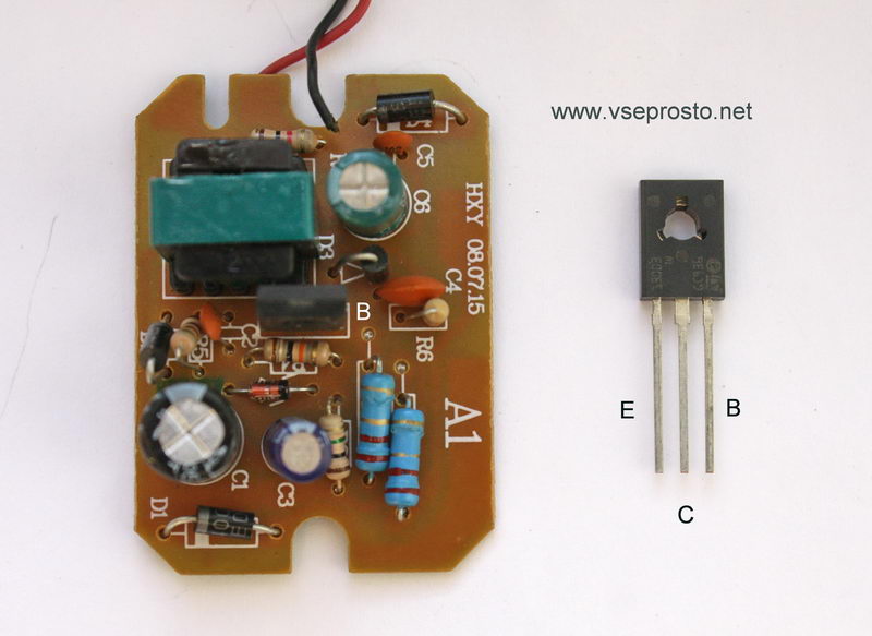
Instead, I put MJE13003. You can put a transistor from any burned out lamp - housekeeper. In them, as a rule, the filament of the bulb itself burns out, and the two high-voltage transistors remain intact.
5. Consequences of overvoltage. In the simplest case, they are expressed in a short-circuited diode D1 and a broken resistor R1. In more difficult cases, the MJE13005 transistor burns out and inflates the capacitor C1. All this is simply changed to the same or similar details.
In the last two cases, it will be necessary, in addition to replacing burned-out conductors, to check the resistors around the transistor. With the diagram, this will not be difficult to do.
The phone is not receiving a charge. The power supply does not work. The charging adapter does not work. All these problems can be caused by elementary breakdowns, which can be easily eliminated using:
- Ohmmeter or multimeter;
- Phillips small screwdriver;
- Low power soldering iron with fine tip;
- Spare parts and parts that can be borrowed from an adapter or phone charger other than a working one.
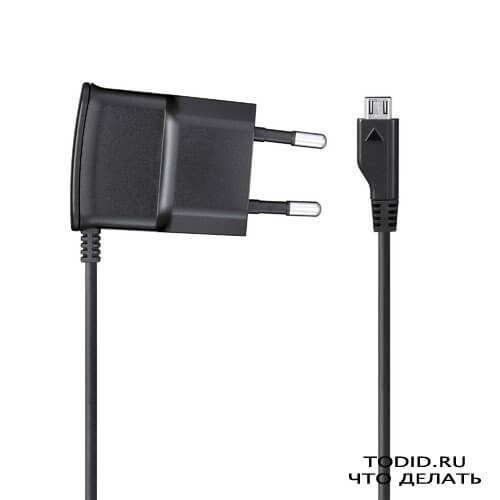
First of all, the site my.housecope.com/wp-content/uploads/ext/2985 emphasizes that there are two types of power adapters:
In any case, the methods described in the article will help to test the device for operability and make easy repairs. This means that the failed device will work again, and you will not have to go to the store for a new power supply or charger for your phone.
How to test the charger for operation and repair the power adapter
1. Pay attention to the indicator, which is located on the body of each adapter. The LED should be on. If this is not the case, it means:
A) the LED is burned out;
B) no electric current is supplied to it.
1.1. We call the wiring using a multimeter or ohmmeter. Important: when measuring the resistance of each wire, we pay attention to the indicators of the multimeter display. A broken wire will have an infinite resistance value. If such a wire is identified, then it is because of it that the adapter (charger, power supply) broke. More often than not, the adapter for the power supply does not work for this very reason.
Note: In order not to break the insulation, sewing needles, stuck wires can be used as lead contacts.
Accordingly, the adapter broke for this very reason, which means that you need to replace the bad wire or fix the gap with a soldering iron.
2. If the wiring is working properly, and the indicator does not light up or the adapter does not charge, disassemble the adapter case by unscrewing the mounting bolts using a suitable screwdriver.
What do we see? Two main blocks:
- A transformer that reduces the voltage to the required value from the standard 220V;
- An electronic circuit that converts alternating current into direct current, brings it to exactly the required values.
Accordingly, the breakdown is hidden either in the circuit or in the transformer. Of course, if there are no noticeable breaks in the contacts between these elements inside the adapter case.
3. Breakdown of a transformer is a break or burnout of a low-quality (probably Chinese) winding.
3.1. You can identify the problem by ringing the primary and secondary windings with a multimeter. This is done like this:
A normal working adapter at the pins of the plug (which is for a socket) has a resistance of several thousand ohms (kilo-ohms, kOhm). If your check reveals this fact, then the primary winding is intact. So, we are looking further
3.2. When checking a transformer, it is important:
- disconnect the adapter plug from the power outlet in advance;
- do not touch the contacts with your hands (this is not dangerous, but it violates the accuracy of objective measurements);
- unsolder the contacts of the electrical circuit from it (if it is faulty, it will affect the ohmmeter readings, introducing confusion).
4. We check the secondary winding to find out why the power supply is not working.
To do this, we measure the resistance of individual diodes from the diode bridge. This bridge is responsible for the electric current flowing through the secondary winding and can interfere with its normal movement, contribute to the breakdown of the adapter (charger, power supply).
You don't have to solder anything from the circuit here. A faulty diode will show zero or too low resistance value. The working diode, accordingly, will show too high, almost infinite resistance values.
5. We pass to checking the electronic circuit. This element of the adapter (power supply, charger) breaks down quite rarely, but it still happens.
Faults and breakdowns are revealed visually here. If the power supply does not work for this reason, then:
- darkening (places of burnout) are noticeable on the diagram;
- capacitors can be swollen, resembling overfilled kegs;
- chips, cracks, any other signs of malfunction will appear on the cases of radio components.
To fix this type of breakdown (if the adapter for the power supply does not work), it is necessary to replace the failed parts with new and working ones. By the way, some work items can be removed from another broken adapter or mobile phone charger.
When soldering, it is important to observe:
- polarity of transformers;
- the correctness of the inclusion of radio components in the electrical circuit.
6. A rare case of adapter breakdown is a malfunction of the stabilizer. If the charger breaks down precisely for this reason, then the stabilizer will be replaced with a new one, and the work will return to normal.
| Video (click to play). |
Important: in order not to confuse the location of the stabilizer terminals, it is recommended to take a preliminary photograph or sketch the circuit elements and connection paths on the sheet. And if the adapter for the power supply does not work for you, it does not hurt to prepare the camera before use. In particular, a photograph taken from a disassembled device will help, without going into details, to solder the working stabilizer and eliminate the cause of the adapter malfunction.

