In detail: bosch fuel pump bosch ve do-it-yourself device and repair from a real master for the site my.housecope.com.
High pressure fuel pump ⭐ (TNVD) is the main structural element of the diesel engine injection system, which performs two main functions: metered fuel supply to the engine cylinders under pressure and determining the correct injection moment. After the advent of battery injection systems, the task of determining the moment of fuel supply is performed by an electronic nozzle.
A schematic diagram of a diesel fuel supply system with a single-plunger distribution fuel pump (TNFP) with a plunger cam drive is shown in the figure:
Rice. Schematic diagram of the fuel supply system of a diesel engine with a single-plunger injection pump: 1 - low pressure fuel line; 2 - thrust; 3 – a pedal of giving of fuel; 4 - injection pump; 5 - solenoid valve; 6 - high pressure fuel line; 7 - fuel line drain line; 8 - nozzle; 9 - glow plug; 10 - fuel filter; 11 – fuel tank; 12 - fuel priming pump (used for long highways; 13 - battery; 14 - ignition lock; 15 - control unit for the time of switching on glow plugs
The fuel pump delivers a strictly metered amount of fuel under high pressure to the diesel cylinders at a certain point in time, depending on the load and speed, so the characteristics of the engines significantly depend on the operation of the high-pressure fuel pump.
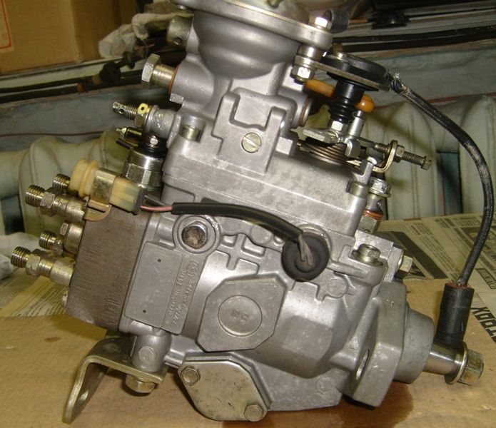
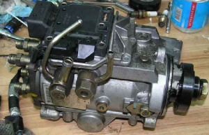
The diagram of the distribution pump VE is shown in the first figure, and its general view is in the following.
The main functional blocks of the VE fuel pump are:
| Video (click to play). |
- low pressure rotary vane fuel pump with control bypass valve
- high pressure unit with distributor head and dosing sleeve
- automatic speed controller with a system of levers and springs
- solenoid shut-off valve that cuts off the fuel supply
- automatic device (automatic) for changing the fuel injection advance angle
Rice. Fuel pump diagram - Bosch VE: 1 - pump drive shaft; 2 - bypass valve for internal pressure regulation; 3 – fuel supply control lever; 4 – regulator weights; 5 - fuel drain jet; 6 - full load adjustment screw; 7 - regulator transfer lever; 8 - solenoid valve for stopping the engine; 9 - plunger 10 - central plug; 11 - discharge valve; 12 - dosing clutch; 13 - cam disk; 14 - automatic fuel injection advance; 15 - roller; 16 - clutch; 17 - low pressure fuel priming pump
Rice. General view of the distribution high pressure fuel pump VE: a - high pressure fuel pump; b - high-pressure block with a distribution head and a dosing sleeve. The positions correspond to the positions in the previous figure.
The distribution injection pump VE can also be equipped with various additional devices, for example, fuel supply correctors or a cold start accelerator, which allow you to individually adapt the injection pump to the features of this diesel engine.
The drive shaft 1 of the fuel pump is located inside the injection pump housing, the rotor 17 of the low-pressure fuel pump and the drive gear of the regulator shaft with weights 4 are installed on the shaft. High pressure fuel pump is carried out from the diesel crankshaft, gear or belt drive.In four-stroke engines, the high-pressure fuel pump shaft speed is half the crankshaft speed, and the distribution high-pressure fuel pump operates in such a way that the translational movement of the plunger is synchronized with the movement of the pistons in the diesel cylinders, and the rotational movement ensures the distribution of fuel over the cylinders. The translational movement is provided by the cam washer, and the rotational movement is provided by the fuel pump shaft.
The automatic speed controller includes centrifugal weights 4, which, through the regulator clutch and the lever system, act on the metering clutch 12, thus changing the amount of fuel supply depending on the speed and load modes of the diesel engine. The high-pressure fuel pump housing is closed from above by a cover in which the axis of the control lever connected to the accelerator pedal is installed.
The fuel injection advance automatic device is a hydraulic device, the operation of which is determined by the fuel pressure in the internal cavity of the injection pump, created by a low-pressure fuel pump with a control bypass valve 2.
There is no more complex and responsible unit in a diesel engine than the fuel injection system, more precisely, its main part - the high pressure fuel pump. Many mating parts, highly loaded units, the presence of a precision dosing system make the repair of high-pressure fuel pumps a difficult task even in service conditions. It is all the more difficult to repair the high pressure fuel pump of a diesel engine with your own hands.
In automotive technology, almost everything is repaired, except, perhaps, individual oil seals and cuffs, the repair of which is impossible without special materials. The complexity of setting up, diagnosing and repairing high-pressure fuel pumps requires the employee to have skills in working with precision mechanics.
It is simply impossible to set up according to factory parameters, without a special diagnostic stand for repairing high-pressure fuel pumps. During the diagnostic study of the injection pump, it is necessary to check:
- cyclic supply of the high-pressure pump, in the entire range of revolutions of the high-pressure fuel pump shaft, at start-up, and after cutting off the fuel supply;
- stability of the developed pressure;
- uniformity of supply of the injected high-pressure fuel pump to the fuel injector.
Even having access to a diagnostic stand, and having studied the issue of repairing a high-pressure fuel pump using numerous videos, it is very difficult to qualitatively check and evaluate its work.
In heavy diesel engines, plunger, in-line injection pumps are used. Such devices are more difficult to maintain and repair, since they require special equipment for disassembling it, so we will not consider such high-pressure fuel pumps and their repair.
In a passenger diesel engine, a distribution-type injection pump is almost always used. Unlike in-line, in a distribution pump, the force on the plunger is transmitted using a profiled cam. The design of the injection pump turned out to be more compact, but it is hardly easier to expect to repair it on the knee.
The most famous and affordable is the Bosh VP44 injection pump. Often, the need to repair the insides of the pump arises when:
- poor traction and incomplete combustion of fuel even under ideal conditions - in the absence of load and a thoroughly warmed-up engine;
- sudden failure and stop of the diesel engine under load, as they say, "death on takeoff." Usually the scanner in such cases diagnoses the code P1630 and P1651.
- the appearance of a leakage of diesel fuel in the area of \u200b\u200bthe gland of the seal of the central shaft of the high-pressure fuel pump.
Therefore, we will limit ourselves to the issue of repairing high-pressure fuel pumps with our own hands by replacing seals and eliminating scuffing of the working surfaces of parts.
Before disassembling the injection pump drive shaft seal, try to move it in the radial direction.If play is felt by hand, the cause of fuel leakage may be the wear of the working surface of the shaft or the bearing needs to be repaired.
A large number of split planes and mating surfaces of parts required the use of a large number of seals and seals. As a rule, they are made of high-quality material and serve for a long time until they are damaged during repair or maintenance. In this case, do-it-yourself Bosch injection pump repairs use standard repair kits.
It is enough to simply replace the seal on the shaft position sensor and on the injection advance control during repair. For a better fit on new rings and rubber bands, you can drop a couple of drops of spindle or engine oil.
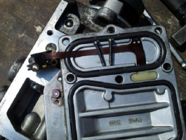
For preventive repair of the Bosch injection pump with your own hands, you will need to disassemble the pump in approximately the following order:
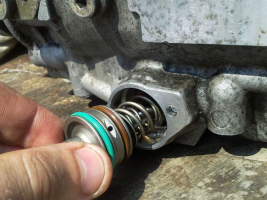
- remove the metering valve from the end part of the injection pump. To do this, unscrew the four screws of the pressure plate, carefully release the injection advance valve cable. After removing the three screws securing the metering valve, you can carefully remove it from the socket;
- by unscrewing the mount on the top cover, you can remove the control board and gain access to the electronics;
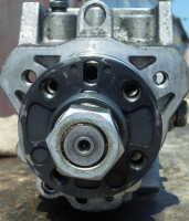
- set the position of the shaft, as shown in the photo, remove the camera and get access to the insides of the injection pump;
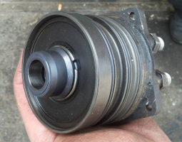
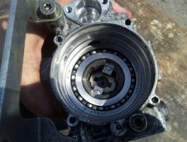
- after dismantling the bearing with the help of a special puller, we get the opportunity to study the potential culprit for the poor performance of the injection pump - the piston of the injection advance unit. Often there is surface wear and tearing on the edges on the part. You can try to repair the surface by polishing, replacing the entire part is much more expensive.
After repair, the assembly is carried out in the reverse order with washing the parts with diesel fuel.
Often, in addition to scuffing, there is another reason on the surface of the pistons why the injection pump does not develop the necessary pressure. This may be caused by debris, films or wax build-up deposited on the filter screen inside the pump. There is a mesh on the side of the inlet pipe. Flushing the channels is troublesome and inefficient, it is easier to remove the mesh and blow it with compressed air.
Broken pieces of debris can jam the plunger piston or even cause the pump drive shaft to break or break. Therefore, cleaning should be carried out very carefully to avoid contamination of the internal cavities of the pump.
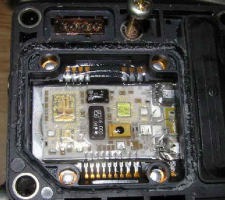
Among the many reasons for the failure of the electronic "liver" of the high-pressure fuel pump, the breakage or burnout of the contacts of the control board and the failure of power transistors are more common than others. If the knowledge and skills of working with electronic devices allow you to “diagnose” the performance of transistors and repair, you should try to identify the cause and replace the culprit with a serviceable element.
To check the condition of the “culprit”, you need to carefully open the black cover, tightly seated on the rubber seal with screws. It should be removed carefully so as not to damage the seal itself.
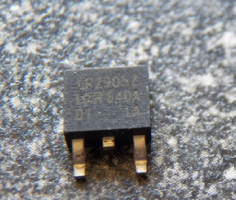
The reason for the failure of not only the transistor, but the entire board could be air that got into the cavity due to poor performance of the drainage system or a check valve. Often they try to eliminate airing by spinning the starter, hoping to pump diesel fuel into the high-pressure fuel pump in this way. At this moment, the transistor is open and loaded to the maximum, which leads to intense heating. In an air environment with poor heat dissipation, it will inevitably burn out. In some German cars, there is protection that prevents an attempt to start the engine in the absence of fuel in the line. To do this, use the fuel sensor in the tank.
The failure of the transistor can be established by a “ring” with a tester or by appearance. The best option to repair such a malfunction would be to replace the entire control board.Perhaps this is more expensive than soldering, but it will give guaranteed quality and stable operation of the high-pressure fuel pump after repair. As a last resort, give the board and the transistor for soldering to specialists - electronics engineers.
When installing and reassembling after repair, check the tightness of all fasteners.
If during the revision process you did not make rash and unreasonable replacements of parts, the assembled pump should work with approximately the same parameters as before. As a standard, for testing and adjusting the injection pump after a major overhaul, the Bosch EPS-815 stand is used.
On the video you can learn how to increase the plunger pressure in the Bosch VE injection pump:
Attention, the editors of the site “Your Road” recommends consulting a specialist before applying this instruction to action.
One of the most mysterious components of a car with a diesel engine is rightfully a high pressure fuel pump (TNFP). There are 2 types of pumps - a mechanical pump and an electronically controlled pump, commonly known as EFI. Each of the types is divided into 2 subspecies: Multi-plunger in-line, single-plunger distribution type (VE). We will not consider “exotics” such as a pump-injector, Common Rail or Distribution pumps of the VR series (Distribution pump with an axial plunger, Distribution rotary injection pump)
Since the device, and therefore the principle of its operation, is a mystery to many, there is an opinion that specialized equipment and a specially trained person are needed to repair it. However, such a “gentleman's” set is not always at hand, so let's try to disassemble and assemble this tricky knot “on the knee”. An injection pump assembled in ancient times from several different types of pumps, without the use of stands, but at the same time successfully spinning a 4D56 diesel WITHOUT TURBINE up to 8000 rpm, will act as an object for preparation. Outwardly, it can differ from the high-pressure fuel pump installed on your car only in the absence of a pressure corrector (a kind of mushroom-hat on the top cover) and some mounted units. It does not change the essence of the matter.
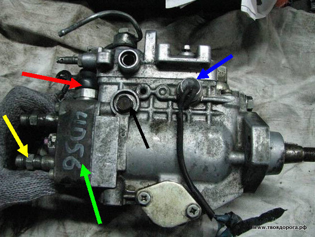
So, on the table- OH.. Top view
The colored arrows indicate:
- Green - fuel supply bolt
- Yellow - "return"
- Black - pressure valve in the injection pump housing
- Red - axis of the fuel supply regulator (drive "gas"). The throttle lever itself has been dismantled for convenience.
- Brown - bolt "quality" of the mixture.
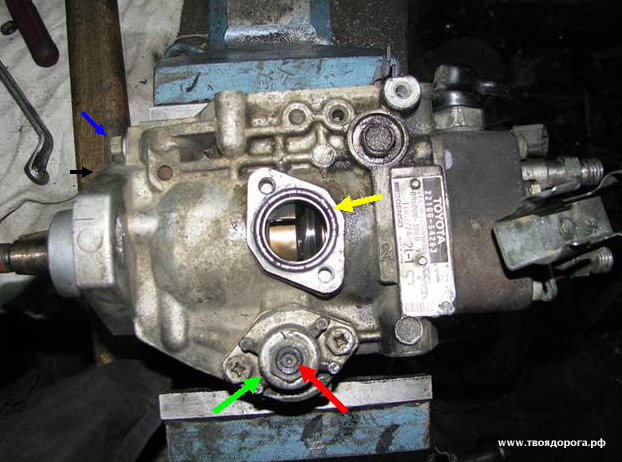
The arrows indicate:
- Black - automatic heating
- Green - automatic warm-up drive
- Red - automatic ignition advance (injection)
- Blue - Identification plate
Side view (back side):
- Blue - speed sensor (tachometer, not always present)
- Red - fuel cut-off valve (silencer)
- Yellow - pressure valve.
- Green is actually a plunger.
- Black - the axis of the fuel supply lever. The same one is on the back of the pump. To move (but not completely unscrew) them is better at the initial stage of disassembly.
For work you will need: a set of heads, a set of hexagons, tweezers, screwdrivers, a gas wrench, a caliper, a vice, a clean rag, a container with clean diesel fuel, grease (Litol, CV joint, etc.), well, the PRE-WASHED patient himself -))
- A mesh filter is installed inside, which, as a rule, cannot be washed. Removal has no "contraindications" (yellow arrow).
- It has a calibrated hole on the side surface (red arrow). Its size is different for different pumps, so replacing it with another one leads to a change in the internal pressure in the pump.
I don't think comments are needed. Tip - the drive itself should not be disassembled.
- Yellow - speed sensor
- Green - "silencer".
- Black - centrifugal speed controller.
- Blue - fuel supply drive lever.
There is one difficulty - to get to one of the 3 bolts. There are only two options:
Disassemble the drive (carefully, there is a powerful spring! + REMEMBER the setting of the adjusting bolt), and then calmly unscrew the rest.
Unscrew 2 “light” turnkey bolts “by 10”, loosen the 3rd, “heavy”, and moving the assembly away, slowly unscrew it.
It should turn out like this:
- Yellow - o-ring
- Red - automatic advance adjusting bolt
- Green - the cover of the advance machine.
- We remember (write down) the departure of the bolt head (red arrow) above the cover (green arrow). If in the process you decide to unscrew this bolt, during assembly you will need to return the dimensions to their original state.
- Blue - the axis of the speed controller.
- Black - mating plane.
Attention! For RIGHT rotation pumps, the thread on the axle will be LEFT and vice versa!
If you can pick up a tool, unscrew the pressure regulator.
Now the fun begins. The analysis includes nodes consisting of several parts. Moreover, the details cannot "live" without each other. That is, they simply cannot be confused with each other.
- Red - pressure valve body
- Green - return spring
- Blue - valve needle
- Yellow - valve seat
- Black - sealing washer.
The plug under the red arrow can not be unscrewed, it serves to install the indicator. The fact is that ignition on diesel engines is set not so much by marks. Rather, initially, the moment of injection is set according to the indicator, and only then the mark that we see is applied. We will omit this procedure for now, the turn will reach it.
So, unscrew the plug (blue arrow). This is where the gas wrench comes in handy. Plug thread - right hand.
- Blue - plunger body
- Red is a plunger.
At this stage, it is necessary to measure the amount by which the plunger is buried in the body. We record the results of the measurement, they will be useful during assembly.
Loosen the fixing screws (but not completely), and CAREFULLY shaking, move the plunger body up. As soon as it is released, finally unscrew the screws and remove the plunger body. You should get this picture:
- Blue - plunger
- Yellow - dosing ring
- Red - washer - bearing
- Brown - base plate
- Black - spring
- Green - adjusting washers.
- Black - plunger adjusting washer
- Red - cam washer.
- Green - fuel supply lever. I managed to take it off earlier.
Attention!! We do not remove the rollers, we do not change their places.
Remove the stopper (shown with a screwdriver).
Under the stopper we see the pin. It is also shown with a screwdriver (it is magnetized, the pin can be easily removed with it).
Remove the cam drive.
We push the axis of the advance automaton into the inside of the vacated space:
For convenience, I deleted 1 video, there is nothing criminal here. For the axis of the advance machine, we pull the roller ring out. Be careful not to overdo it! At the slightest misalignment, the ring jams in the body. Attempts to pull it out “insolently” will end deplorably - the pump housing will go to waste.
It should look something like this:
For the 2 “horns” sticking out in the bowels of the pump, we take out the pump shaft with the regulator gear:
We return to the "remains" of the pump:
We release the bolts (blue arrows) and take out the cover of the booster pump (red arrow).
Turn over the pump housing.
We remove the gland (shown with a screwdriver). Warning - do not try to save it, it will not work anyway.
As a result, a bare body with a sleeve pressed into it should remain. Here's one:
2009, spring, while repairing a car, I thought that it would be nice to do high-pressure fuel pumps, since I have been sinning against him for a long time. Symptoms are poor starting, cold jerkiness and gray-blue smoke. In addition, in the summer I took a sip of water in the ford, after that, the car began to drive a little worse, after a while, a rather large lump of dirt was pulled out of the fuel filter. There is still water and dirt in the tanks.I did not see the return line, since the hoses are opaque. I decided that I would change the oil seal on the injection pump shaft, and at the same time clean it from dirt. In addition, one friend advised me to clean the grid, supposedly he had the same garbage on the same car. Mesh in front of the plunger. If you think about it, and at the same time remember the condition of the filter, then I won’t be surprised if everything is clogged with dirt there.
I took off the injection pump, before starting work, I washed it.
In the photo, to the left of the fuel supply bolt to the high-pressure fuel pump, there is a pump bypass valve head, the good news is that there was no dirt under it.
I thought for a long time and decided to completely remove the USR, so I want to eliminate the resistor from the injection pump. On my engine, it doesn't affect anything else.
In order to be able to get to the grid, you will need to dismantle the high pressure section - “cast iron”, for this we unscrew 4 screws at the edges.
The photo shows what the injection pump looks like with the cover removed. You may notice that there is a brownish coating on the walls, it lies everywhere in an even layer. I washed off this plaque easily. The feed control shaft is tight, there are no signs of wear, fuel does not ooze.
View of the injection advance valve plunger.
In general, I removed the cast iron (high pressure unit). I got to the mesh, blew it, then put everything back together.
Plunger (the edges of the grooves are very sharp).
"Cast iron" with a cylinder (I don't know what it's called) and a grid.
The grid is located at the entrance to the plunger pair.
There was no noticeable dirt on the grid, but just in case I blew it with a compressor.
Another view of the interior.
Finally, I got to this grid, blew it out, put the cast iron in place. When disassembling, the pump was clamped in a vice for the “cast iron” bracket was at the top, I removed the “cast iron”, and left the plunger and rollers in place. , after my intervention, the creak of rubber became audible, besides, as it seemed to me, the shaft began to rotate more difficult. I double-checked everything, like all the details are in their places, they stand as they should. When I changed the oil seal, I did not check the rotation, did not compare it with what it was before the replacement and which became after the replacement. Instead, I immediately took up the removal of the "cast iron" and therefore did not check.
As I understand it, nothing could fall out, get enough sleep and stand crookedly in its place, I also could not confuse the slots, the plunger is not a wavy washer, it can only be put in one position. Well, the creak, most likely from the stuffing box. When installing it, I dipped the stuffing box in diesel fuel just in case, and cleaned the shaft. In the photo there is a washer under the plunger. You need to change it unequivocally. The fuel supply parameters depend on it. In this photo, it is located on a wavy washer, at the workplace. (It seems to be at work, since I didn’t take it apart carefully, it fell out while removing the washer, so I don’t remember the initial position. In the sense - on the other side or not).
The same washer, only removed and turned upside down. With the naked eye, you can see the development on the working parts.
Plunger end. Wear is present.
Plunger. The edges of the grooves are very sharp (like a razor).
I dismantled the pump completely, the insides are scattered in random order.
All parts must be thoroughly washed in clean diesel fuel, as well as blown with compressed air. Any grain of sand can spoil the whole work.
When repairing, the seals in the pump must be replaced.
I used pre-made kits. For convenience, I sorted them into a case. Not everything is here. The prepared case is fixed on the assembly stand.
All preparation consists in grinding some working surfaces with sandpaper, its grain size should be from 400 to 1200. Most often used 800. This is how the working wall of the booster pump, the inner walls and bushings of the pump shaft look after grinding.
In the photo, the cavity of the injection advance corrector plunger (denoted as timer) This is a low-pressure pump, in a simple way it can be called: a booster pump.
Its task is to pump fuel from the tank into the body cavity, the fuel is pumped under the correct pressure. The pressure reducing or bypass valve is responsible for this (it is not shown in the picture). The operation of the timer and the engine directly depends on the pressure (this is a very important parameter).
All parts, except for the centrifugal governor drive gear, can be replaced with new ones if necessary. Most often, the stator, rotor and petals are changed.Much less often cover and shaft.
The prepared body is rubbed and blown.
In my case, the right-hand rotation pump, i.e. rotor rotates counterclockwise. I think this photo will help to understand how it works. First, the rotor, stator, petals and walls expand, form a cavity, fuel is sucked into it from the inlet channel during formation, then they narrow, thereby throwing fuel into the supply channel in which the pressure reducing valve is located.
I hope it’s clear, in most cases, for a left-hand rotation pump, you can use a pump from the right one, for this you need to turn it over. Of course there are nuances, but it would take too long to describe them.
I think you understand what water will do here. The stator enters the housing very tightly, its edges are sharp enough, if you skew and start hammering during installation, the housing will be sent to the trash with a stuck stator. Before installation, I lubricated it, and only then put it in place with gentle blows around the perimeter.
We put the cover, it is desirable to lubricate the threads of the screws. For example, I usually use (Castrol LMX) to lubricate the rotor.
Experience shows that hot diesel fuel does not dissolve it.
Repair kit FLAG.
The necessary repair kit can be selected from the catalog for any pump. By and large, they differ in the diameter of the seals.
Work surfaces are polished. I washed the parts, wiped them, blew them with compressed air, and now put them in clean diesel fuel. Rubber "crackers" that connect the shaft with its gear part, which drives the centrifugal regulator.
I installed new ones, lubed them with LMX. At the same time, I lubricated the keyway, shaft and washer.
Some lubrication is necessary so that the washer and key do not fall out during installation.
We continue to work, you need to carefully align the groove of the booster pump rotor with the shaft key. Personally, the first time I didn’t manage to put the shaft in place without difficulties.
The clip of rollers is established from above. It should also be lubricated on the outer working part. If it is more defective, it is necessary to control the condition of the nests under the roller axis, if there is noticeable wear, replacement cannot be avoided. You can put it without any effort and special tools.
It is connected with the clip of rollers by the movable axis of the timer. If you change the internal pressure, the injection advance piston rotates the roller cage, it will change the injection angle accordingly.
It is also set to the timer:
The working surface of the timer must be polished. A fairly common malfunction is a timer wedge with foreign debris. Symptoms, the engine loses enough power, starts to smoke, knock and does not gain momentum.
The timer lubricated the LMX and installed it in the case, exactly in this position.
Next, it must be pushed into the body to the middle position.
Rotate 90?, slide in the pin connecting it and the roller cage, then fix it with a small pin and a spring clip.
It is advisable to check the smoothness of movement and the absence of jamming. We put new sealing rings. I use LMX to lubricate the seals. View of the left (in this case) cover of the timer. Under it is a spring and shims.
There is not much to write about them. In short, the spring tension must be selected on the stand. I selected the tension according to my own feelings, after installation, the timer can be adjusted by changing the internal pressure, you will have to rely on hearing. And of course this is wrong.
The rollers themselves. Depending on the condition of the axles, the working surface and backlashes, they either change to new ones, or the axle and the working surface are polished and everything is put in place. Chipping, risks, tarnishing marks are not allowed, the knot is extremely loaded.
The rollers are set in place.
Be careful not to confuse the position of the washer on the roller and which side you put it on. If the videos are mixed, there is nothing to worry about.
Cross washer. The output from the shaft is noticeable on it.
We turn it 90 degrees so that further work takes place in the place where there is no development. You also need to check and, in which case, put in order the rest of the work surfaces.
We put it in place, the spring is not needed yet.
The injection characteristic depends on the profile of the cams (see marking in the photo), i.e. from the buildup of pressure. The work surfaces are in order. Sometimes this happens:
The cam disk is in its place, the pin under the plunger heel is located in the same way as the keyway on the injection pump drive shaft.
So far without washers, springs and dispenser rings. We select washers according to the thickness under the heel of the plunger, size K, a rather important parameter when adjusting the injection pump. The pair is installed, the plug is unscrewed from the pair, the plunger should be at the bottom of the stroke.
Norm = 3.5 mm in our case.
Next, we begin to install washers and a dispenser on the plunger. Washers must be defective and surfaces prepared accordingly. Remember to pay attention to the position of the washers and the hole in the dispenser.
We proceed to adjust the second, no less important parameter - Kf. The measurement method is the same, except that the spring is installed, we hold the pair in our hands. I will set the size to 5.8 mm. The photo shows flat shims.
Along the way, you need to control that the washers are of the same thickness, and the springs must be even and always the same length.
Now we fix the pair (without the plunger) in a vice and begin to wrap the plug, it is desirable to lubricate the threads and the thrust surfaces.
Special head for plug.
Some tried to do it with gas wrenches.
Next, you need to check the working surfaces at the delivery valves, check the markings, then do not forget to rinse and blow. We put in the body of a couple:
You can see the stages: a brand new copper washer from the repair kit, spring, valve, fitting. The thread of the fitting must be lubricated, no special effort is needed.
The spring is installed under the cam disc:
We install the plunger pair in the body, it is installed in a horizontal position, fixed with screws, it is not necessary to tighten it. We put the dispenser drive springs, I put them on lubrication, since they fall out differently.
The screws for fastening the dispenser drive to the housing need to be screwed in, it is advisable to replace the copper washers. I remember that there were some problems with them.
Next, we begin the installation of the dispenser drive.
It is necessary to ensure that you get into the recess of the dispenser, as well as that the springs do not fall out and are not warped.
Once in place, the drive shaft bolts can be tightened. (There is a special triangular head for this). Next, we proceed to the assembly and installation of the centrifugal regulator, the rubber on its axis must be changed. Do not forget that the screwing depth of the axis is normalized. In practice, you need to combine the end of the axle with the plane of its locknut.
In the event that a warm-up automatic is installed, here put a unit that, depending on the coolant temperature, will shift the feed control lever, and also will shift the roller cage through the hole in the housing, thereby changing the injection angle (on a cold engine it changes to early side).
On the axis of the control lever, we change the rubber ring, again, do not forget to lubricate it.
Set the control lever in place. By that time, the plunger pair is already in place, the screws are carefully tightened, the fuel cut-off solenoid valve is installed. The seal under it has been replaced, it is advisable to check the valve with operating voltage.
Next, you need to carefully install the gland, try not to warp. The working edge must be lubricated, during installation the gland must be displaced, try not to damage the working edge on the edges of the keyway.
Now, you need to carefully replace the top cover of the pump.Do not forget to check the return fitting for patency (there is dirt in the fitting in the photo), we blow it, the return line does not need to be tightened until the pump is pumped by the manual fuel pump, which is on the filter.
That's all, now you need to install the entire external “body kit”, levers, sensors, supply pipes, brackets on the pump, after which it can be installed on the engine.
“Diesel Market” – Engine parts: pistons, rings, liners, gaskets, sprayers, spark plugs, plunger pairs, injection pumps
AUTOWELT – spare parts for engines of Japanese and European cars
| Video (click to play). |
DENSODIESEL – central distributor of DENSO for diesel injection systems in Russia

