In detail: do-it-yourself diagnostics and repair of the motherboard from a real wizard for the site my.housecope.com.
- Power supplies for IBM PC-XT / AT system modules (djvu in rar3.30 = 900 kb):
The revised book by A.V. Golovkov and V. B. Lyubitsky describes in detail and with numerous examples the device and principles of operation of a standard push-pull half-bridge power supply of the AT standard. (Taken here.)
- PCI Local Bus Specification Revision 2.1 (pdf in zip = 2.4 mb)
- PCI Local Bus Specification Revision 2.2 (pdf in zip = 3.5 mb)
- PCI Local Bus Specification Revision 3.0 (pdf in zip = 2.8 mb)
- Accelerated Graphics Port Interface Specification Revision 2.0 (pdf in rar 3.0 = 2.9 mb)
- AGP V3.0 Interface Specification Revision: 1.0 (pdf in rar 3.0 = 580 kb)
- AGP Pro Specification Revision: 1.1a (pdf in rar 3.0 = 1.2 mb)
Everything is quite old here, there are already many fixes and additions on the wiki.
wiki.rom.by/index.php/Category: Tutorial_by_re .
In crooked hands, the rug is buggy.
Lena, you miss us. Uryayaya.
I'm glad to see you too.
I suggest an unconditional redirect from here to the wiki.
Due to the abundance of questions from enthusiasts who prefer to do everything with their own hands, regardless of profitability, we decided to help understand the actions called - motherboard repair.
The article written here does not cover all the secrets associated with repairing motherboards and the given tips will not solve the problem of a step-by-step guide for a beginner, experience is needed here.
But, nevertheless, they will show the way and give information for thought and some basic points, which in skillful hands will be a good help in business motherboard repair.
| Video (click to play). |
1. Before turning on the motherboard, you need to make it preliminary inspection... This is especially true in the area of CPU power supply, since if the CPU VRM fails, there is a risk of processor burnout.
If one of the transistors or microcircuit is damaged, then such a board cannot be turned on. If you suspect a malfunction of these elements, it is necessary to measure the resistance between the control legs of the transistors and the ground. These resistances for the upper transistors (their left legs) should be the same, just like all lower transistors (right legs), the resistances should be the same (hereinafter, the top will be called the side of the board closest to the external COM, USB, etc. etc .; bottom - IDE connectors side; right - CPU side). In case of VRM CPU malfunctions, the above resistances have obvious deviations and usually have very small values. It should be noted that failures of the processor power circuits on Intel motherboards are quite rare.
If the VRMs are working properly, you can install the CPU processor, POST-card and turn on the board. Testing must be done with a known working processor.
2. Can be produced turning on the power supply... The power supply is only switched on when the CPU is installed. If the motherboard includes a power supply, then the following values are checked:
- voltages on quartz legs;
- resistance between the 3.3V power supply (orange wire and ground) when the power supply is disconnected from the motherboard and the CPU and RAM are removed.
It is necessary to check whether any elements are hot, especially pay attention to Super I / O (combines the interfaces of various low-frequency devices and includes the following functions: floppy controller, LPT, COM-port, MIDI or IRDA ports) and south bridge.
Maybe, motherboard turn on when the 12V power supply pin of the CPU is pulled out. Check whether the board will turn on forcibly by shorting PS_ON (green and black wires of the power supply unit), if it turns on again, check if the above elements are not getting hot.
3. If the motherboard is turned on does not output any codes to the POST card or is in RESET , you need to check the availability:
- CPU supply voltage (lower output of the coils);
- voltage at the bottom terminal of any of the resistor assemblies under the RAM connectors;
- voltage on the RESET button (one wire sits on the ground, the voltage on the second terminal is of interest);
- voltages on quartz legs;
- voltage on the 15th top right pin of any PCI slot;
Check if any elements are not hot, especially Super I / O, south bridge, LAN, BIOS.
And also on the off board:
- resistance between 3.3V STDBY (regulator substrate U9B3) and ground;
- resistance between the left leg of Q6E2 and the ground;
- resistance between the 3.3V power supply (orange wire and ground) with the power supply pulled out from the mother, the CPU and RAM removed.
4. Next, make board inspectionespecially in the area of the conductors connecting the northbridge to the CPU and the northbridge to the southbridge. Are the contacts in the PCI, DDR slots closed? Reinstall the CPU, check for starting with a strongly pressed CPU, pressed corners of the south bridge, strongly pressed BIOS, with any slight bends of the board.
5. Next, you need to check if does the motherboard see memory (in both channels). She must squeak without memory, and move on with memory. A memory failure is indicated by code D3, D4 (check both banks). In case of memory faults, you need to measure the voltage at the lower terminal of any of the 56-ohm resistor assemblies under the RAM connectors.
With the board off:
- measure the resistance between the top right contact of AGP (A1) and 12V power supply (yellow wire) - should be 0 ohm; if 12V does not reach pin A1, then with a video card inserted, the code is usually D3; it is also necessary to check the integrity of the AGP connector;
- measure the resistance between pins 91 and 92 (usually signed) of the DDR socket and ground;
- visually check the integrity of the conductors from the north bridge to the faulty memory bank, as well as the integrity of the resistor assemblies and the DDR connectors themselves.
6. If the motherboard does not see AGP video cards, you need to check the availability:
- voltage on contact A1 AGP (top right);
- voltage on the bottom contacts of the AGP connector;
- check the integrity of the AGP connector, the presence of all legs;
- check the integrity of the conductors from AGP to sowing. bridge.
Perhaps the video card will be seen if you slightly bend its upper or lower corner or reposition the card several times.
7. In all other casesif the motherboard executes any codes, but does not reach the operating system load, you must try to flash the BIOS. BIOS also needs to be flashed on working boards, which ensures guaranteed confidence in the future absence of glitches from the BIOS. Particularly clear signs of the need for BIOS firmware are codes 03 (it means that the old BIOS is stitched up, which does not understand the inserted CPU) and E9 (BIOS checksum error). The E9 code occurs especially often due to a missing or bad contact in the BIOS CONFIG jumper, while the FDD is accessed.
BIOS flashing is very simple. A file with the BIOS image of this board is written to a blank formatted floppy disk, the floppy disk is inserted into the FDD, the BIOS CONFIG jumper is removed, the board is turned on, the board performs all BIOS flashing actions itself and then turns off. This action is short-lived and is accompanied by sounds. The keyboard, video card is not used. Use a guaranteed working BIOS for the firmware.
In the life of every home craftsman who knows how to hold a soldering iron in his hands and use a multimeter, there comes a moment when some complex electronic equipment breaks down and he has to make a choice: take it to a service for repair or try to repair it on his own. In this article, we will break down the techniques that can help him with this.
So, you have broken any equipment, for example LCD TV, where do you need to start repairs? All craftsmen know that it is necessary to start repairs not with measurements, or even immediately re-soldering the part that aroused suspicion of something, but with an external examination. This includes not only inspecting the appearance of the TV boards, removing its cover, for burnt radio components, listening in order to hear a high-frequency squeak or clicking.
To begin with, you just need to turn on the TV to the network and see: how it behaves after turning it on, does it respond to the power button, or the standby LED blinks, or the image appears for a few seconds and disappears, or there is an image, but there is no sound, or vice versa. By all these signs, you can get information from which you can push off with further repairs. For example, in the blinking of the LED, at a certain frequency, you can set a breakdown code, self-test of the TV.
TV error codes by flashing LED
After the signs are installed, you should look for a schematic diagram of the device, or better if a Service manual for the device is released, documentation with a diagram and a list of parts, on special sites dedicated to electronics repair. It is also not superfluous, it will be in the future, to drive into the search engine the full name of the model, with a brief description of the breakdown, conveying in a few words its meaning.
True, sometimes it is better to look for a diagram by the device chassis, or by the name of the board, for example, a TV power supply. But what if the circuit still could not be found, and you are not familiar with the circuitry of this device?
In this case, you can try to ask for help on specialized forums for the repair of equipment, after carrying out preliminary diagnostics on your own, in order to collect information from which the masters who help you can push off. What stages does this preliminary diagnosis include? To begin with, you must make sure that power is being supplied to the board, if the device shows no signs of life at all. It may seem trivial, but it will not be superfluous to ring the power cord for integrity, in the audio dial mode. Read here how to use a regular multimeter.
Tester in sound dial mode
Then the fuse is ringing, in the same multimeter mode. If everything is fine with us here, you should measure the voltages at the power connectors going to the TV control board. Typically, the supply voltages present on the connector pins are labeled next to the connector on the board.
TV control board power connector
So, we measured and we do not have any voltage on the connector - this indicates that the circuit is not functioning correctly, and we need to look for the reason for this. The most common cause of breakdowns found in LCD TVs are banal electrolytic capacitors with an overestimated ESR, equivalent series resistance. Read more about ESR here.
Capacitor ESR Table
At the beginning of the article, I wrote about the squeak that you may hear, and so, its manifestation, in particular, is a consequence of the overstated ESR of small capacitors standing in the standby voltage circuits. To identify such capacitors, a special device is required, an ESR (ESR) meter, or a transistor tester, although in the latter case, the capacitors will have to be soldered for measurement. A photo of my ESR meter that allows you to measure this parameter without soldering is posted below.
What if such devices are not available, and suspicion fell on these capacitors? Then you will need to consult on the repair forums, and clarify in which node, which part of the board, the capacitors should be replaced with obviously working ones, and only new (!) Capacitors from the radio store can be considered as such, because used ones have this parameter, ESR may also be off scale or already on the verge.
Photo - swollen capacitor
The fact that you could remove them from a device that previously worked does not matter in this case, since this parameter is only important for working in high-frequency circuits, respectively, earlier, in low-frequency circuits, in another device, this capacitor could function perfectly, but have an ESR parameter that is highly off-scale.The work is greatly facilitated by the fact that capacitors of a large denomination have a notch in their upper part, along which, if they become unusable, they simply open, or a swelling forms, a characteristic sign of their unsuitability for any, even a novice master.
Multimeter in Ohmmeter Mode
If you see blackened resistors, you will need to ring them with a multimeter in ohmmeter mode. First, you should select the 2 MΩ mode, if the screen shows values that differ from one, or the measurement limit is exceeded, we should accordingly reduce the measurement limit on the multimeter to establish its more accurate value. If there is a unity on the screen, then most likely such a resistor is in an open circuit, and it should be replaced.
Resistor color coding
If it is possible to read its denomination, according to the marking with colored rings applied to its case, it is good, otherwise, one cannot do without a diagram. If the circuit is available, then you need to look at its designation, and set its rating and power. If the resistor is precision, its (exact) value can be dialed by connecting two ordinary resistors in series, larger and smaller, the first we set the value roughly, the last we adjust the accuracy, and their total resistance will add up.
Transistors are different in the photo
Transistors, diodes and microcircuits: it is not always possible to determine the malfunction by their appearance. A measurement with a multimeter is required in the audible dial mode. If the resistance of any of the legs, relative to some other leg, of one device is zero, or close to it, in the range from zero to 20-30 ohms, most likely such a part must be replaced. If this is a bipolar transistor, you need to call in accordance with the pinout, its p-n junctions.
Checking the transistor with a multimeter
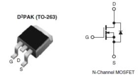
Most often, such a check is enough to consider the transistor as working. A better method is described here. In diodes, we also cause a p-n junction, in the forward direction, there should be numbers of the order of 500-700 when measured, in the opposite direction, one. The exception is Schottky diodes, they have a lower voltage drop, and when dialing in the forward direction, the screen will display numbers in the range 150-200, in the opposite direction there is also one. Mosfets, field-effect transistors, it is not possible to check with an ordinary multimeter without soldering, it is often necessary to consider them conditionally working if their outputs do not ring among themselves shortly, or in low resistance.
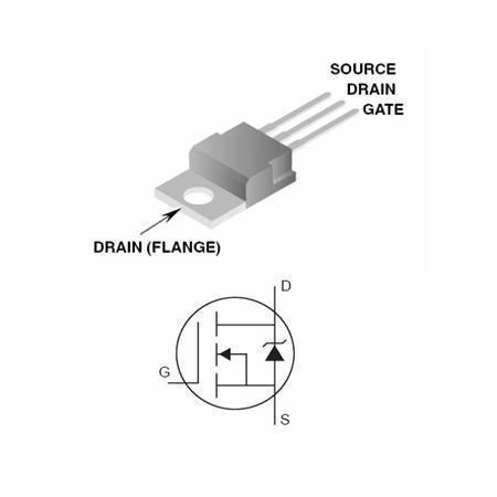
Mosfet in SMD and regular case
In this case, it should be borne in mind that the mosfets between the Stock and the Source have a built-in diode, and when dialing, there will be readings of 600-1600. But there is one nuance here: if, for example, you ring the mosfets on the motherboard and hear a sound signal at the first touch, do not rush to record the mosfet in the broken one. In its circuits, there are electrolytic filter capacitors, which, at the moment of the start of charging, as you know, for some time behave as if the circuit is short-circuited.
Mosfets on the PC motherboard
This is what our multimeter shows, in the mode of sound dialing, squeaking, for the first 2-3 seconds, and then increasing numbers will run on the screen, and the unit will be set as the capacitors charge. By the way, for the same reason, in order to save diodes of the diode bridge, a thermistor is installed in the switching power supplies, limiting the charging currents of electrolytic capacitors, at the moment of switching on, through the diode bridge.
Many familiar novice repairmen are shocked - you tell them to ring the diode, they will ring and immediately say: it is punctured. Here, as a standard, the explanation always begins that you need to either raise, remove one leg of the diode, and repeat the measurement, or analyze the circuit and the board, for the presence of parallel-connected parts, in low resistance.These are often the secondary windings of a pulse transformer, which are just connected in parallel with the terminals of the diode assembly, or in other words, a double diode.
Parallel and series connection of resistors
Here it is best to remember once, the rule of such connections:
- When two or more parts are connected in series, their total resistance will be greater than the greater of each, separately.
- And when connected in parallel, the resistance will be less than that of each part. Accordingly, our transformer winding, which has a resistance of 20-30 Ohm at best, by shunting, imitates a “punctured” diode assembly for us.
Of course, unfortunately, it is not realistic to reveal all the nuances of repairs in one article. For preliminary diagnostics of most breakdowns, as it turned out, a conventional multimeter used in the modes of a voltmeter, ohmmeter, and sound dial is sufficient. Often, if you have experience, in the event of a simple breakdown, and the subsequent replacement of parts, this is where the repair is completed, even without the presence of a circuit, carried out by the so-called “scientific poke method”. Which of course is not entirely correct, but as practice shows, it works, and, fortunately, not at all as shown in the picture above). Successful repairs to everyone, especially for the site of the Radio Circuit - AKV.
How to repair your computer yourself? In the event of a breakdown, not all users are ready to return the faulty device to the SC or use the services of specialists who repair computers at home. Many are trying (with varying degrees of success) to understand the breakdown and fix it without outside interference. If you dare to produce do it yourself computer repair, you need to know the basic principles of its operation. By the way, Scott Mueller's excellent book "Upgrading and Repairing Your PC" can help you with this. It describes in an accessible and simple language such topics as: the history of the emergence and development of computers, the evolution and structure of processors, the principles of functioning of motherboards, hard drives and other equipment, assembly, modernization and repair of a computer with your own hands.
For a successful computer repair, it is advisable to have a good knowledge of the materiel. The above book will help you with this. Possession of assembly skills and the practice of repairing at least some kind of electronic equipment will also come in handy. And finally, the most important thing: you need to have a head on your shoulders and preferably not empty. When repairing a computer, you will have to analyze, compare, draw conclusions, think ... If you are not inclined to this, or if you consider yourself a born humanist, it is better not to try.
Computer repair must begin with diagnostics... Competent diagnostics is already a half-solved problem! To diagnose a faulty computer, you will need utilities such as Memtest (memory test), ViktoriaHDD (hard disk test), AIDA64 (general information about the system, stress tests, component temperatures). Download links for each, I will give in the section corresponding to their application.
If you are doing a do-it-yourself computer repair for the first time, a short table of faults will be of great help. You will have to analyze the appearance of the components, computer beeps (BIOS POST signals). It should be noted that sometimes even a working computer may not give any POST BIOS sound signals due to the absence of a speaker (also called a "beeper") connected to the "SPKR" pins on the motherboard.
Sometimes it is soldered tightly to the motherboard, sometimes being connected via a cable, it is hidden in other wires going to the front panel.
If you took up computer repair yourself or decided to do it on a professional basis, an extra speaker, aka POST Speacker, will not hurt you.
I collected all the dead and half-dead boards of the Pentium 2-3-4 class
and decided to consider their malfunctions, and it is possible to develop some general approach to their search.
It seems that those present here will help with considerations.
It appears here. first of all, we disconnect from the patient who has turned on (usually he is still dressed in a case and entangled with wires)
Be careful not to remove the cooler with a screwdriver.
All loops, pieces of iron, we take out the boards, etc.
leaving only video, processor and memory.
turn on ..
1) It works - look at the hardware, change cables to peripheral devices, deal with resource conflicts and BIOS settings
2) Didn't help. - We change the power supply unit, processor, video card for obviously working ones (optional, if available at hand) - this helps to find out and locate the troubles. Important note -
When changing a processor, it is often necessary to control its frequency, division ratio, and generation, set by jumpers,
Modern boards usually have a Jumper-Free design, that is
with autodetection of these parameters. Or they have settings in BIOS, and reset to automatic processor detection occurs when you press a key when you turn on the computer - like Alt-F2 or “D” or “R” or “Del” ..
When installing another AGP video card, check that it is compatible with the motherboard, otherwise the mother can be completely burned. details and differences of AGP 1.0 2.0 and 3.0 standards read at IXBT.com
The memory should also be checked. But don't confuse modern Pentium-4 DDRs with PC-100 or PC-133 DIMMs for Pentium 2-3 class machines.
Reset BIOS settings using 3-pos. jumpers near the round battery .. Usually it is signed, but often it is the only one on the entire board. it is called Clear CMOS
has 1-2Normal 2-3 Clear positions.
We put 2-3 and turn it on for a short time.
Then we go back and try again.
We take out, gently bending the holder with a fingernail,
shiny little lithium battery. we measure her tension -
it should be at least 2.5-2.8 volts. If less -
it is better to change it, it costs 10-15 rubles. It happens when the mother stands for a long time, then the voltage on the battery drops, but the mother can start up with the battery installed, although the time and BIOS settings will fly off
to the factory.
3) It didn't help - We unscrew and take out the mother - often there is a problem in the screwing places - either the case bent the motherboard, and a microcrack opened up inside it. (and in motherboards the getinax is multilayer, and the number of layers with tracks can be from 4 to 12. Therefore, you need to solder and unsolder something from it with care.) We put the board on an insulating substrate on the edge of the case, and try again by weight -
The power supply is connected to the motherboard (in Class P-4 typewriters there can be two or even more loops to supply power to the motherboard - they must all be connected!)
The rest of the power supply cables are disconnected from all devices, even the flop.
Did not help.
So - from this moment we have the motherboard in our hands.
the most important point is inspection.
First of all, we look at the capacitors-barrels. They usually
swell and interfere with work. If the conduits are swollen, then often they are immediately visible, and moreover, they have to be changed in bulk - 10 pieces at a time. This comes from overclocking, increasing the supply voltage to the processor, chipset, etc., in BIOS, often from overheating, but the main reason is low-quality cheap Chinese conductors. =)
They exchange specialists. Do not take away from them their bread, but from themselves the last hope (I remind you that the motherboards are multilayered.)
then we look inside all the bus processor connectors - AGP, PCI, memory connector, etc. - often they get foreign objects, insects, broken legs, shavings, paper, etc. ...
Such connectors also need to be changed by a specialist. In principle, they change, I have performed such organ transplants more than once.
don't try this at home.
Next, we look through a magnifying glass carefully at the tracks on the back of the board and on the surface. Often the problem is buried in them. You can see the burned-out track, and with proper qualifications and ability to work with a soldering iron and small objects, you can even eliminate this defect yourself by soldering thin wires in the burned-out place
But the problem is usually deeper - for example, if the PCI bus power track burns out - then perhaps the reason is in one of the cards, for example, in the sound card. it is better to replace a suspicious card and inspect it carefully.
The same damage includes marks from a screwdriver and other tools with which you tried to remove the fan from the processor.
The screwdriver cuts the tracks near the processor, usually in the most inaccessible place, and it will not do without removing the processor socket from the board. Run to the workshop =)
! Yes, I forgot - an important part of the information about board malfunctions can be learned from the signals it sends to the speaker
or by an error code that can be read from the built-in 2-segment LED indicator on some mothers.
There was one server that generally said it all to the speaker in English =)
These codes and sounds are called POST. i.e. Power-On Self-Test or Power-On Self-Test.
I would be glad if someone posts a link or a sign ..
for example - one long BIIIP - this is a memory malfunction, Two short one long - either Video, or the keyboard is not connected. Now these codes are not at hand - maybe I will find them later, I will add them.
Now to the masters -
the only thing left is to calm the client down, once again examine everything carefully, and check the voltages on the conductors with an oscilloscope - sometimes the dried-up is indistinguishable from the worker.
There should be no “noise”. Then check the power keys.
(I will ask a more knowledgeable person to write about the procedure for this test, the only thing is that they should not call by zero.)
Also check if the voltage supplied to the board is normal. - on the connector. It happens that the “Power Good” signal from the power supply sinks with a large current consumption when the motherboard is connected, below 4 volts and the board does not turn on in principle.
What else have we forgotten?
Yes, it is possible that the BIOS flew - it was beaten by a virus - well, here it is, reprogram the mikruhu - you need a programmer, find the firmware on the Internet, it is possible to unsolder the microcircuit with the BIOS, etc.
What other malfunctions were there?
Everything that the boards could. - I have now fixed questions about the switching circuit of quartz and clock generator microcircuits,
- some of the quartz that I measured with an oscilloscope had a generation on two legs - it was mainly working quartz for working mothers .. And some mothers that do not start - have generation on only 1 quartz leg. Here I sit and break my head - maybe there is such a switching circuit? Microcircuit for example Realtec 660-109 (from memory) ..
I haven't found it in the internet yet .. 🙁
I will be glad for the info.
The book deals with practical issues related to the repair of personal computers at home or office.
After reading it, you will learn about methods for eliminating common computer malfunctions, learn how to check its performance, identify devices that have failed, and select a suitable replacement for them. The pages of this publication provide recommendations on how to prevent problems and keep your computer running. The material is presented in a simple and intelligible form, so even a novice user will be able to understand it.
Diagnostics of malfunctions of MP
There are several ways to diagnose a motherboard.
First of all, take a close look at your motherboard. If there is mechanical damage on it, see if the conductive connections are broken. Chipping at the edges is possible.If the damage only touched the PCB - the insulating base on which the board is mounted, then, most likely, nothing terrible happened. If the contacts, conductive tracks are damaged, then the motherboard will most likely stop working.
Remember that the presence of mechanical damage is a reason for refusing to accept payment for warranty service at the service center.
The detection of darkening of the PCB indicates that the components installed on the board were overheating. In this case, you need to check the cooling: whether the processor fan is working, the fan installed on the motherboard microcircuit. Perhaps you need to install an additional fan in the case or replace the unsuccessful case altogether. If in case of overheating any element is out of order, contact the service center.
If you saw blackening, traces of soot on the motherboard, its elements, then there could be a fire in this place. This usually happens due to a short circuit. If, in the presence of such traces, the board continues to work, test it, as it is prone to failure later.
If there are traces of oxidation on the board, then it has practically begun to deteriorate. Even if you clean the places where the board is oxidized, over time it will stop working or will not work correctly. It is best to replace such a board with a new one.
If a crack or scratch is found on the board that has destroyed the conductive connection, the conductors are connected by soldering. But it should only be produced with the appropriate experience. It is very important here not to touch the neighboring conductors, otherwise the MP will have to be thrown away, since the short circuit of the current-carrying conductors will instantly lead to the failure of the board (it is possible that not only the board will fail). The warranty department will not accept the board on which the soldering was performed, there are scratches, cracks.
If multiple tracks are damaged, copper hairs are needed, for example, from low-voltage wires. Free the area of the damaged track on the MP from the varnish, tin it and solder the copper hairs to the places of damage.
A board that has deep cracks, scratches will most likely need to be replaced as multiple layers of the board may be affected. There is hope to correct the defect only if the top layer is damaged.
If the legs of the microcircuits are touched, their deformation is possible. Do not try to return the legs to their original position, as they can come off, it is possible that the MP will have to be changed after that. Spread the legs so that there is no short circuit between them, a scalpel and a magnifying glass will help you with this.
If a part that is not marked is damaged, you will have to look for another faulty board of the same model and rearrange the part from it. This is a complex process and does not always end with success.
If you have a problem with a processor socket, changing it at home is extremely difficult. It is better to hand over such an MP to a service center.
Any electronics fail over time. However, not all owners of computer equipment are able to understand the cause of this or that electronic problem. Now we are surprised from the start: a safe do-it-yourself motherboard repair is possible and quite real even in the performance of a beginner. It’s hard to believe, but practice shows that only a small percentage of computing devices that arrive at service centers in a state of complete or partial inoperability really requires a complex recovery process. The rest of the "electronic troubles" are resolved quickly and on the spot, that is, without the use of complex repair equipment and specialized computer knowledge. This article is dedicated to those who believe in themselves and their abilities, who do not want to waste time and money.
In order to repair motherboards with your own hands, you need very little patience and some basic knowledge.Therefore, first of all, calm down - everything will work out for you. Regarding the last condition, we read and remember the following:
- Do not forget that the computer is powered from the mains, from which the logical conclusion follows: you need to follow the security measures known to you (otherwise you need to carefully study the issue) - this is the main thing!
- Second, you simply cannot do without a Phillips and a regular screwdriver.
- Third, if you want to understand as much as possible how to repair motherboards with your own hands, then you also need to arm yourself with a multimeter.
And before completing this section, the last condition: maximum attention and increased care in work. As you can see, there is really a little of the above. However, there is one more thing that should be mentioned: the components of a computing system can be damaged by static stress. Therefore, your body needs to "discharge". Touch an unpainted part of the central heating radiator, or touch another grounded object. During repair work with a PC, periodically repeat the "unloading scenario".
- The most common computer system connectors fail: COM, PS / 2 and USB. In the event that the user constantly connects a mobile device for data transfer or uses another peripheral device, it may well be that the heavily used port will be mechanically damaged.
- Power surges have a detrimental effect on all computer components. As a rule, as a result of such fluctuations, fuses and passive electronic components of the system, such as capacitors, are the first to burn.
- If one of the coolers is out of order, then when the computer is turned on, the temperature protection will most likely be triggered. Turning on the PC will simply not be possible.
- It is very rare, but still relevant for the list of "motherboard malfunctions": there is a failure of the BIOS firmware. In this case, the computer can respond to the power-on command, but this is where its "live" state is usually limited.
First of all, make sure the connected device is working properly. It is possible that as a result of mechanical action, the integrity of the soldering itself was violated. Carefully go through a soldering iron (40 watts is quite acceptable power) at the joints of the socket parts. Replacing the port is more time consuming and often involves the risk of damaging the harness components adjacent to the part being removed. This is how the motherboard is arranged, so it is better to contact a specialist with the problem that has arisen. By the way, it may well happen that the connector you are interested in is disabled in the BIOS settings of the program. Go to the base system and check if this is the case.
If your PC systematically "falls" into the unknown, and the screen is filled with blue and incomprehensible white text, then you should pay attention to the critical components of the system.
- The CPU may be overheating due to an inadequately working cooling system.
- The RAM does not match the configuration of the PC or is physically damaged.
- The hard drive has reached its limit or needs a software repair.
The improper functioning of any of the above system components can lead to a deplorable situation - a complex repair of the computer motherboard will be required. Remember that the biggest enemy of computing devices is overheating. The cooling system must always be in good working order, and the fans must have sufficient power to ensure that the optimal temperature regime is maintained for the stable operation of all hardware components of the system.
Do not panic if your PC emits unnatural sounds at the time of startup - this signals the BIOS to you about a specific malfunction. Due to the difference in modifications and the typical dissociation of computing devices, each separately presented manufacturer uses its own signal scheme. Therefore, it is impossible to say unequivocally what will mean a short "peak" and a long "pi and and". The decoding of audio messages can be found on the official website of the manufacturer of a particular device. Then proceed according to the information received. By the way, don't forget to replace the battery on the board. However, in some cases, when it is necessary to reflash the BIOS chip, you may need special equipment - a programmer.
So, how do you repair the motherboard yourself under such malfunction conditions? A practical example with step-by-step recommendations is waiting for you, dear reader. It is worth noting that in the course of the behavior of the diagnostic method described below, a multimeter is required.
- Turn on the computer and make sure that the LED on the motherboard is on - its active state indicates that there is a standby voltage on the main board.
- In the case when there is no such indicator, you need to connect a known working power supply.
- If the result remains zero, that is, when the PC starts up, it is “silent”, disconnect all attachments: dismantle the CPU cooler and the processor itself, remove the memory sticks from the special slots, disconnect the hard drive, discrete video card and network adapters.
- Examine the system board carefully for oxidation and physical damage. You may find swollen capacitors or other malfunctioning components.
- Relying on the marking of the defective parts, replace them.
As you can see, repairing motherboards with your own hands is, in general, not a difficult process, but some difficulties still await you further.
With the power supply turned on, sequentially and carefully touch your hand to the network, audio and chipset microcircuits. If you feel that any of the parts is overheating, then there is only one way out - contact a service workshop. All is well - let's move on.
- Some motherboards are capable of starting without a CPU installed, under this condition, you can measure the voltage on the board's power bus and make sure that the converter is working.
- Set the multimeter to the “20 volt” position.
- Insert the negative probe into the power supply terminal of the PSU (to the ground), and with the positive one alternately touch the lower leg of each choke (they are located in close proximity to the motherboard socket). If the returned value is close to 0.8, everything is in order. Otherwise, it is necessary to find the punctured transistor from the power harness or replace the faulty voltage regulator. Of course, all this is done after you briefly touch the positive probe on the starting contact of the Power Bat.
| Video (click to play). |
We've covered the highlights of how to repair motherboards. However, due to the incredible variety of reasons for non-inclusion and various system "glitches", the presented methods of diagnosing and restoring the performance of the motherboard may turn out to be incompetent. However, you now have some knowledge that will certainly help you bring your beloved computer back to life. All the best to you and successful motherboard recovery processes!

