Details: dt 838 DIY repair from a real master for the site my.housecope.com.
When repairing electronics, you have to carry out a large number of measurements with various digital instruments. This is an oscilloscope, an ESR meter, and what is used most often and without the use of which no repair can do: of course, a digital multimeter. But sometimes it happens that help is required by the instruments themselves, and this happens not so much from the inexperience, haste or carelessness of the master, as from an annoying accident, such as happened to me recently.
DT Series Multimeter - Appearance
It was like this: after replacing the broken field-effect transistor during the repair of the LCD TV power supply, the TV did not work. An idea arose, which, however, should have come even earlier, at the diagnostic stage, but in a hurry it was not possible to check the PWM controller even for low resistance or a short circuit between the legs. It took a long time to remove the board, the microcircuit was in our DIP-8 package and it was not difficult to ring its feet on the short circuit even on top of the board.
Electrolytic capacitor 400 volt
I disconnect the TV from the mains, wait for the standard 3 minutes to discharge the capacitors in the filter, those very large barrels, electrolytic capacitors for 200-400 Volts, which everyone saw when disassembling a switching power supply.
I touch the probes of the multimeter in the mode of sound continuity of the PWM controller legs - suddenly a beep sounds, I remove the probes in order to call the rest of the legs, the signal sounds for another 2 seconds. Well, I think that's all: again 2 resistors burned out, one in the resistance measurement circuit of the 2 kOhm mode, for 900 Ohm, the second for 1.5 - 2 kOhm, which is most likely in the ADC protection circuits. I had already encountered a similar nuisance, in the past a friend hit me with a tester in the same way, so I did not get upset - I went to the radio store for two resistors in SMD cases 0805 and 0603, one ruble a piece, and soldered them.
| Video (click to play). |
Searches for information on the repair of multimeters on various resources, at one time, gave out several typical schemes, on the basis of which most models of cheap multimeters are built. The problem was that the reference designations on the boards did not match the designations on the found diagrams.
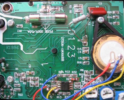
Burnt resistors on the multimeter board
But I was lucky, on one of the forums a person described in detail a similar situation, the failure of the multimeter when measuring with the presence of voltage in the circuit, in the mode of sound dialing. If there were no problems with the 900 Ohm resistor, several resistors on the board were connected in a chain and it was easy to find it. Moreover, for some reason it did not turn black, as is usually the case during combustion, and it was possible to read the denomination and try to measure its resistance. Since the multimeter contains precise resistors that have 4 digits in their designation, it is better, if possible, to change the resistors to exactly the same ones.
There were no precision resistors in our radio store and I took the usual one for 910 ohms. As practice has shown, the error with such a replacement will be quite insignificant, because the difference between these resistors, 900 and 910 Ohms, is only 1%. Determining the value of the second resistor was more difficult - from its terminals there were tracks to two transition contacts, with metallization, to the back of the board, to the switch.
Place for soldering thermistor
But I was lucky again: two holes were left on the board connected by tracks in parallel with the resistor leads and they were signed by RTS1, then everything was clear. The thermistor (РТС1), as we know from the pulse power supplies, is soldered in order to limit the currents through the diodes of the diode bridge when the pulsed power supply is turned on.
Since electrolytic capacitors, those very large barrels of 200-400 volts, at the moment the power supply is turned on and the first fractions of a second at the start of charging, behave almost like a short circuit - this causes large currents through the bridge diodes, as a result of which the bridge can burn out.
To put it simply, a thermistor has a low resistance in normal mode when small currents flow, corresponding to the mode of operation of the device. With a sharp multiple increase in current, the resistance of the thermistor also increases sharply, which, according to Ohm's law, as we know, causes a decrease in the current in the circuit section.
Resistor 2 Kom Ohm on the diagram
When repairing on the circuit, presumably we change to a 1.5 kΩ resistor, the resistor indicated on the circuit with a nominal value of 2 kΩ, as they wrote on the resource from which they took the information, during the first repair, its value is not critical and it was recommended to put it, nevertheless, at 1.5 kΩ.
We continue... After the capacitors are charged and the current in the circuit has decreased, the thermistor decreases its resistance and the device operates normally.
900 ohm resistor on the diagram
Why is a thermistor installed instead of this resistor in expensive multimeters? With the same purpose as in switching power supplies - to reduce large currents that can lead to the burnout of the ADC, arising in our case as a result of an error of the master conducting the measurements, and thereby protecting the analog-to-digital converter of the device.
Or, in other words, that very black drop, after the combustion of which the device usually no longer makes sense to restore, because this is a laborious task and the cost of parts will exceed at least half the cost of a new multimeter.
How can we solder these resistors - perhaps beginners who have not previously dealt with SMD radio components will think. After all, they most likely do not have a soldering hair dryer in their home workshop. There are three ways here:
- First, you will need an EPSN soldering iron with a power of 25 watts, with a blade blade with a cut in the middle, in order to heat both terminals at once.
- The second way, by biting off with side cutters, a drop of Rose or Wood's alloy, immediately on both contacts of the resistor, and flatten both of these terminals with a sting.
- And the third way, when we have nothing but a 40-watt soldering iron of the EPSN type and the usual POS-61 solder - we apply it to both leads so that the solders mix and as a result, the total melting temperature of the lead-free solder decreases, and we heat both leads of the resistor alternately, while trying to move it a little.
Usually this is enough for our resistor to be sealed off and stick to the tip. Of course, do not forget to apply the flux, it is better, of course, liquid Alcohol rosin flux (GFR).
In any case, no matter how you dismantle this resistor from the board, bumps of old solder will remain on the board, we need to remove it using a dismantling braid, dipping it in an alcohol-rosin flux. We put the tip of the braid directly on the solder and press it, warming it up with the tip of the soldering iron until all the solder from the contacts is absorbed into the braid.
Well, then it's a matter of technology: we take the resistor we bought from the radio store, put it on the contact pads that we freed from the solder, press it down with a screwdriver from above and touch the pads and leads located on the edges of the resistor with the tip of a 25-watt soldering iron, solder it in place.
Solder Braid - Applications
The first time, it will probably turn out crooked, but the most important thing is that the device will be restored. On the forums, opinions about such repairs were divided, some argued that due to the cheapness of multimeters, it makes no sense to repair them at all, they say they threw it out and went to buy a new one, others were even ready to go all the way and re-solder the ADC). But as this case shows, sometimes repairing a multimeter is quite simple and cost-effective, and any home craftsman can easily handle such a repair. Successful repairs to everyone! AKV.
Repair of the S-Line DT-838 multimeter
I checked the transistors with a tester and they turned out to be all defective, I almost threw them out. And it turned out that the multimeter turned off.(ha ha)
And so the multimeter was buggy but measured the resistances and squeaked on the call. The voltage showed normal.
I didn’t find such a scheme, I found this one:
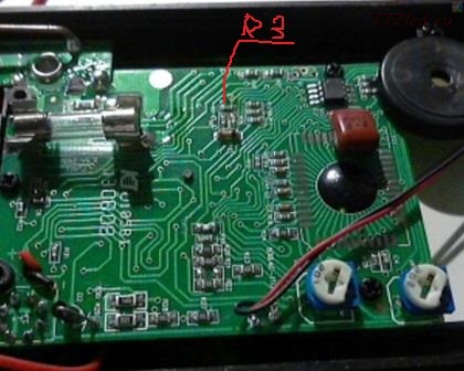
Having disassembled it on the board, I noticed that R3 (the marking on the board, the diagram is different) there is a small dot (152 is written on the resistor) 1.5 kOhm, having measured it with another multimeter (it is generally buggy, but you can navigate) showed more than 2 kOhm.
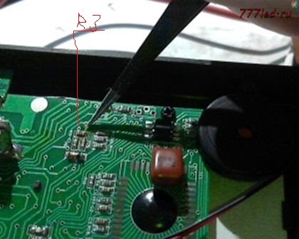
After the replacement, everything worked. I took the resistor from the old motherboard of the computer, soldered it off and soldered it with a hairdryer to a homemade soldering station.
please tell me the value of the resistor R16
very necessary or a scheme if there is
thanks in advance!
I have 561 written on resistor R16, this is 560 Ohm.
Here is a photo that is really hard to see
The same ((
Where is this cut on the mother? did not see ((tell me, or what to replace (where to drop out)?
Found ... soldered ... did not work ((
more precisely, it is still buggy.
Repairing the dead is good. What about eliminating factory (Chinese) defects? Now DT-838 are sold (allegedly) from different brands (Ermak, Resanta, TEK), but with the same defect that appears ONLY when measuring temperature. Temperatures above 100-150 C are overestimated, and the higher they are, the more they are overestimated (see graph).
Heating a thermocouple from the multimeter kit in a lighter flame can easily get 1999 C and even overload. In reality, it is quite difficult to get even 1000 C on a lighter, and at 1500 C the thermocouple conductors should have already melted.
The point, of course, is not in the thermocouple, but in the multimeters themselves: with the next Chinese "optimization" an error crept in, which has been successfully replicated ever since. Reviews mentioning the defect by Russian sellers are simply not published (I did not check all of them - one was enough)
I just found an error (in the PCB layout) (with a sweat). It is not difficult to fix it. The temperature becomes correct, but the correction has no effect on other modes. I will probably post this somewhere more appropriate.
Repairing the dead is good. What about eliminating factory (Chinese) defects? Now DT-838 are sold (allegedly) from different brands (Ermak, Resanta, TEK), but with the same defect that appears ONLY when measuring temperature. Temperatures above 100-150 C are overestimated, and the higher they are, the more they are overestimated (see graph).
Heating a thermocouple from the multimeter kit in a lighter flame can easily get 1999 C and even overload. In reality, it is quite difficult to get even 1000 C on a lighter, and at 1500 C the thermocouple conductors should have already melted.
The point, of course, is not in the thermocouple, but in the multimeters themselves: with the next Chinese "optimization" an error crept in, which has been successfully replicated ever since. Reviews mentioning the defect by Russian sellers are simply not published (I did not check all of them - one was enough)
I just found an error (in the PCB layout) (with a sweat) and fixed it. It is not difficult to fix it. The temperature becomes correct, but the correction has no effect on other modes. I will probably post this somewhere more appropriate.
Perhaps the most common and inexpensive digital multimeter. Disadvantages - a large error, especially in the cold, poor protection, marriage. The series of digital multimeters DT (M) -830-838 is basically similar in construction, but there is a difference in designations, ratings and circuits.
The bit point flashes, shows any nonsense.
The reason is poor contact in the measurement switch. Disassemble the device and check whether the ball is in place in the switch, stretch the spring slightly pressing this ball for better switching. Wipe the switch contacts with alcohol. Replace battery.
The readings jump when measuring resistances, the other modes work - the resistor R18 (900 Ohm) is faulty or the transistor Q1 (9014) is faulty.
Incorrect readings during measurement - open circuit R33 (900 ohm)
The readings jump when measuring the current strength - resistors R0, R1.
I took this DT-838 multimeter on the market as not working at a ridiculous price. He had a practically new case, which I wanted to put on my battered, cracked and burnt soldering iron, but a working multimeter DT-830.According to the seller, the multimeter was defective.
And of course, first I decided to try to repair the purchased multimeter. After inserting the battery and turning on the multimeter, I saw that it turned on and numbers appeared on the screen, but the multimeter did not want to react to any measurements.
There were traces of soldering on the board - apparently they tried to repair the multimeter unsuccessfully. Inspection of the board with a magnifying glass gave its result - near the middle socket for the probe there was a crack on the board and the track leading from the probe was broken. Apparently, during the previous repairs, they did not see this and limited themselves to simple soldering of the contacts for the probes.
I cleaned the track of varnish and soldered, at the same time and re-soldered the connectors for the probes, assembled, turned on - a cursory check showed that the main functions are working properly.
The process of repairing the DT-838 multimeter in the photo below (you can click to enlarge)
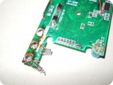
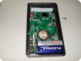
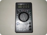
That's how I ended up with a practically new multimeter and almost free. And all due to the fact that the developers of this multimeter did not provide a stop for this part of the board, so when the probes are connected, the board bends, which led to a crack. Well, and also because of an inattentive previous repair.
Once I measured the mains voltage of 220V, but I didn’t blindly notice that the device was in the resistance measurement mode. He poked him once, twice, three times ... The device could not stand such mockery and quietly ordered him to live a long time. Several resistances burned out, and, most importantly, the ADC. This device, one might say, costs a penny, but this is my old friend and comrade in arms, we went with a lot of things, many different memories are associated with it. So I decided to try to restore it.
Of the whole variety of M838 multimeter circuits, it came to me from the DT-838 (almost one-to-one), here it is:
First, you need to deal with the "drop" of the native ADC that was in the device initially. To do this, I assembled a 60 Hz square-wave generator according to this scheme (it started to produce stable 60 Hz at + 6V supply voltage):
When checking, the output of the common wire of the generator is connected to the signal electrode of the indicator, and the other outputs are alternately fed with a signal from the output of the generator. This will activate the corresponding segments of the indicator. As a result of the check, firstly, the pinout for the 32-pin LCD indicator of the 800 series multimeters was determined, and also the purpose of the remaining ADC pins became clear. The result is shown in the figure:
Pin assignment of the old ADC
We also note that the ICL7106 does not have a BAT output, so you will have to collective farm the battery discharge indication yourself, according to this scheme, taken from one of the many circuits for 832 multimeters:
A small batch of five ICL7106 was purchased from our Chinese friends on ebay (in reserve, and you never know ... I took 250 rubles each, now they cost 410 rubles).
Then, taking into account the previous measurements, I made an adapter card for the new ADC and soldered the microcircuit there:
I soldered the legs there - it turned out such a many-legged:
And we solder it to the multimeter board (before that, just in case, I cut the tracks from the old ADC "drop"):
And voila - the device came to life! It was only necessary to slightly adjust the divider of the reference voltage with the resistor VR1 (highlighted in the photo) for a more accurate display of the result:
On the right, the battery discharge control circuit is highlighted, it works at a voltage below 7V (usually about 8V, but I made myself 7 - it is adjusted by resistor R3), although the device remains operational even at 3V, although this does not guarantee the correct measurements.
The conclusion is this - be more careful with the devices, inattention can lead to sad consequences.
4 devices of this type have accumulated, I will give all three for spare parts, or maybe one of them can be restored? name tel. workshop, if possible.
Perhaps the most common and inexpensive digital multimeter. Disadvantages - a large error, especially in the cold, poor protection, marriage. The series of digital multimeters DT (M) -830-838 is basically similar in construction, but there is a difference in designations, ratings and circuits.
The bit point flashes, shows any nonsense.
The reason is poor contact in the measurement switch. Disassemble the device and check whether the ball is in place in the switch, stretch the spring slightly pressing this ball for better switching. Wipe the switch contacts with alcohol. Replace battery.
The readings jump when measuring resistances, the other modes work - the resistor R18 (900 Ohm) is faulty or the transistor Q1 (9014) is faulty.
Incorrect readings during measurement - open circuit R33 (900 ohm)
The readings jump when measuring the current strength - resistors R0, R1.
Fan
Group: Participant
Posts: 2900
User #: 463
Registration: 14-June 05
Place of residence: Russia
This post has been edited Asmodey - Mar 15 2008, 09:57 PM
Partner in crime
Group: Participant
Posts: 695
User #: 21271
Registration: 1-June 07
Place of residence: Ukr. Kharkov
Partner in crime
Group: Participant
Posts: 362
User #: 13810
Registration: 25-November 06
Why can't a person find the videos they want on Youtube? The thing is that a person cannot come up with something new and look for it. He was out of fantasy. He has already watched a lot of various channels, and he no longer wants to watch anything (from what he watched earlier), but what to do in this situation?
In order to find a Youtube video that suits your needs, it is imperative to keep searching. The harder your search is, the better your search result will be.
Remember that you only need to find a few channels (interesting), and you can watch them for a whole week or even a month. Therefore, in the absence of imagination and unwillingness to search, you can ask your friends and acquaintances what they are looking at on Youtube. Perhaps they will suggest original vloggers that they like. You, too, may like them, and you will become their subscriber!
Online mp3 cutting is convenient
and a simple service to help you
create a musical ringtone yourself.
YouTube video converter Our online video
the converter allows you to download videos from
YouTube website in webm, mp4, 3gpp, flv, mp3 formats.
These are radio stations to choose from by country, style
and quality. Radio stations all over the world
over 1000 popular radio stations.
Live broadcast from webcams is made
absolutely free in real
time - broadcast online.
Our Online Television is more than 300 popular
TV channels to choose from, by country
and genres. Broadcasting of TV channels is free.
A great opportunity to start a new relationship
with a continuation in real life. Random video
chat (chat roulette), the audience is people from all over the world.
Forum RadioKot
Here you can meow a little 🙂
Time zone: UTC + 3 hours [Daylight Saving Time]


Yes, there were some from Tektroniks. Thank you. [/ Quote]
Sorry, I was mistaken - from HP, not Tektroniks. Thank you.
JLCPCB, 10 PP prototypes for only $ 2 and 2 days delivery!
_________________
scio me nihil scire.
______________________________________
More precisely, two and at different times.
I don’t know what happened, but something slipped through the power supply of the multimeter and burned out (at least) the JRC 2904 opamp (in SO-8) case.
Found a replacement - LM2904N. Did I pick it right? If not, what can be replaced?
The body of the mikruhi is different. I had to tinker, but it seems to be installed fine.
But! The display almost always shows 1808 and the no power indicator (battery icon). In the positions of temperature measurement, short circuit and any one position in the measurement of direct, alternating current and current, it shows a rupture. But, for example, when checking the short circuit, the speaker beeps, but the image on the display does not change.
Just wondering what could be the cause of the malfunction?
Could it be that the display is displaced (it is not fixed on the board, but is pressed by the board against the rubberized contact groups)?
Another multimeter of the same model, but completely different inside.
Once when measuring the change in the network jumped. So that the legs were burned off at the contacts to which the probes are attached.
Then he soldered the wires, checked the tester as best he could. Everything seems to be alive.
But it measures only short-circuit. Beeps and display 0 shows.
In other positions, there is always a break (1 in the most significant bit).If you try to measure the voltage in the network, you hear clicks.
Can such a malfunction tell someone something? Can you win?
Analog multimeters were very quickly pushed out of the market by devices based on ADCs (analog-to-digital converters). This happened for a number of objective reasons (compact size, high accuracy, clarity of the provided result, acceptable cost, etc.), however, such measuring devices also have a number of disadvantages.
And the most significant is the complexity of the repair.
Firstly, modern manufacturers are very reluctant to share the schematic diagrams of devices, which greatly complicates the troubleshooting.
And, secondly, the microcircuit underlying the device is difficult not only to diagnose, but also to replace (often the crystal is not just soldered to the board, but also additionally filled with solid glue, which protects the crystal and also increases heat transfer).
Description of multimeters DT 832
The 830 series multimeters are very popular. They combine wide functionality and low cost. These devices are based on the ICL1706 ADC IC developed by MAXIM. Although at the moment there are many analogues from competitors, there is even a Russian implementation - 572PV5).
The original series of measuring instruments is marked as M832, the DT modification is a cheap analogue from Chinese manufacturers. Nevertheless, the functionality and the main scheme are preserved.
The multimeters are suitable for measuring voltages from 200 mV to 1 kV (for DC), currents from 200 μA to 10 A and resistances from 200 Ohm to 2 MΩ.
So, the main radioelements are indicated in the diagram below.
Rice. 1. Schematic diagram
To understand the basic logical connections between the nodes of the device, you can study the functional diagram.
Rice. 2. Functional diagram
It is best to take out the conclusions of the microcontroller separately.
The most interesting thing is that, even with a schematic diagram in hand, it will be very problematic to fix a multimeter. To understand why this is happening, it's easier to see everything once.
Rice. 4. Microcircuit underlying the device
The microcircuit is flooded, and the contacts are not indicated in any way, which significantly complicates the ringing of problematic elements, the control points are not indicated.
Due to the fact that there are a lot of reasons for breakdowns, below we will consider the most common.
Rice. 5. Fixing parts of the device
1. Broken switch... Due to the poor quality of the lubricant, literally after a few years, there may already be a noticeable difficulty in switching the mode. Another common problem is the fallout of the pressure balls (pictured above). In this case, the device stops working altogether, and a characteristic noise is heard in the case when shaking. The defect is repaired by simple reassembly and lubrication (it is best to use silicone) of the switch.
2. Burnout of individual elements... A very popular type of breakdown, when during the measurement process the switch is not moved to the desired position, and the resulting load exceeds the permissible value. In this case, in certain types of measurements, there are problems with the correctness of the received data. For diagnostics, you must have a circuit with known parameters or another working multimeter. When disassembling, it is very easy to find a burnt element. It will turn black. The problem is solved by replacing it with a full analogue (it is necessary to use the schematic diagram above to clarify the nominal value).
3. The screen goes out (when turned on, it lights up normally, but later it goes out smoothly)... The problem is most likely in the clock generator. In this case, the driving elements of the oscillatory circuit are C1 and R15. They must be checked and replaced if necessary.
4. The screen goes out, but with the cover removed it works as expected... With a high probability, the back cover touches the resistor R15 with the contact spring and short-circuits the master oscillator. The problem is solved by shortening the spring (or bending it).
5. In voltage measurement mode, the readings change spontaneously from 0 to 1... Most likely a problem with the integrator circuit. You can check and, if necessary, replace capacitors C2, C4, C5 and resistance R14.
6. In resistance measurement mode, the readings are set for a long time... Check and replace C5.
7. The data on the display is cleared for a long time... Most likely the problem is in the capacitor C3 (if the capacity is normal, it can be replaced with an analogue with a reduced absorption coefficient).
8. In any of the selected modes, the multimeter does not work correctly, the microcircuit itself heats up... It is necessary first of all to check if there is a short circuit in the terminals connected to the connector to test the transistors. You can look for a short circuit in other places in the circuit.
9. Individual segments disappear and appear on the LCD... With a high degree of probability, the conductivity through the rubber inserts (through which the display is connected to the board) has deteriorated. It is required to disassemble the connection, wipe the contacts with alcohol, tin the contact pads on the board if necessary.
This is not a complete list of possible malfunctions. A thorough visual inspection of the device, analysis of control point indicators and ringing of hotel elements will help to find them. For verification with the "norm" it is best to have on hand a known working DT 832 (as a reference).
- Evgeniy / 09/14/2018 - 17:12
The schematic diagram does not correspond to either the photograph (or the model itself). - Alexander / 06/25/2018 - 13:59
multimeter DT832 board 8671 (832.4c-110426) the photo matches my multimeter, but in the diagram the resistors do not match the number of ohms. For example, I have 6R4 = 304, 6Rt1 = 102.6R3 = 105, 6R2 = 224, Rx2 = 205, and there are other numbers in the diagram above.
You can leave your comment, opinion or question on the above material:
Marya Ivanovna: E and E write through O
And I did that once. When I burned one 830. I went and bought a second one exactly the same. I opened both and started comparing. Since there are no strips left in the burned out resistor. Then I found burnt, seemingly intact. There was also a third shop. She measured it. Replaced about 4-5 resistances. With a tolerance of up to 10%. Actually, there was a sports interest - it will work al no.
Unfortunately, it didn't work. The attachments were all serviceable. Apparently, the microcircuit is also covered.
Then, out of interest, I began to compare the circuits of more expensive avometers. Found out an interesting thing. As a rule, the microcircuits are the same. To measure advanced parameters, such as temperature, frequency, diodes in a separate mode, and something else, only additional input circuits are used. The cost of a penny. And the cost of the device itself increases significantly. Marvelous !
No wonder - this is very often done in serial production - it is easier and cheaper to do everything on one platform where you can "miss" the details and you will get a junior model


I have a "good" DT-838 (all the time on the LCD -1). Replaced the ADC with a case-C7136D (Germany). Result: there are digits that “run” all the time on the lower ranges of resistance measurement, even zeroing at short circuits. probes. What can this beat?
Thanks in advance.
There was a similar malfunction, maybe your resistor burned out
https://my.housecope.com/wp-content/uploads/ext/1366/measure/5291/
A very useful article, where the principle of operation of the M832 multimeter with the 7106 ADC is very clearly described:
https://my.housecope.com/wp-content/uploads/ext/378/izmer/izmer48.php
This article helped me figure it out when repairing my multimeter.
And in Lviv you don't learn to write in Russian at all?
The question arises - the economic feasibility of repairing THIS cartoon ?! I would understand another 890 series, but THIS.


KRAB: I would understand another 890 series, but THIS.
And what about sports interest? - where to put it? .. it has nothing to do with any economic feasibility ...

Tension with pinout: where to solder viv. No. 37. Soldered to the LCD but the display went out.
Date: 18.09.2015 // 0 Comments
Choosing their first multimeter, many often face the problem of price, because good instruments cost a lot of money, and cheap Chinese multimeters don't inspire confidence. Today we have a multimeter in our hands DT 838, and we will conduct a quick review of it, perform a couple of tests, and also compare this device with more expensive counterparts.
The tested sample DT 838 is not new, it is about 5 years old, the price of which is currently about 5-6 USD.
This device is supplied in a cardboard box with instructions, in our case it was even in Russian, and a temperature sensor is also included in the kit. As you can see from the switch markup, the DT 838 has very limited functionality.
The measuring range of alternating voltage starts from 200 V, which, in principle, is permissible for household needs, but when an alternating voltage of several volts is applied, a significant error appears in the multimeter. The modes for measuring alternating current are not implemented at all, but on the whole this is a device that is not bad in terms of functionality for its meager price. There is a possibility of measuring temperature, but he measures it very approximately.
The body is made of fragile plastic, such a device must be treated with care and try to avoid any drops or bumps. Examining the insides, you can notice hack-work soldering, as well as influx of plastic in different places and other minor manufacturing defects.
On the reverse side of the board there are contact paths of the switch. As you can see, they wear out over time, traces of the switch appear even on the tracks of the board, which can provoke their fraying and premature failure of the device.
Separately, the problem of probes should be taken out, they are of disgusting quality. During operation, they will constantly break off and break. In this case, I would like to advise you to replace them immediately.
A multimeter was taken for the test Unit 151B, it is a higher quality instrument that allows you to visually compare the readings of the test sample.
Test 1... Voltage is supplied to both devices at once, the source is a 5V power adapter. As you can see, the range of instruments in the readings is only 0.05 V.
Test 2. A 24 V car light is connected to the same adapter. It is lit at a quarter of the incandescence, both multimeters are connected in series with it in ammeter mode. The readings differ by 0.06 A.
Test 3. The resistance of the resistor marked 2.7 kOhm is measured in turn. As you can see from the photo, both devices show 2.69 kΩ.
Next, the resistance of a resistor marked with 100 kΩ is measured. Then there was a difference in readings of 0.1 kOhm.
As you can see from the tests, even the cheapest multimeter can show quite good results. But in practice, this is not entirely true, often such devices are famous for their inaccurate readings.
Before buying cheap Chinese multimeters such as DT 838, it is recommended to stock up on several proven resistors, etc., or even better, take a good and accurate multimeter with you, with which you can test the purchased sample and choose the best from the lot that is in the store.
- master_tv

- Offline
- Moderator

- Electronics Repair Engineer
- Messages: 3613
- Thanks received: 246
- Reputation: -4
It is impossible to imagine a repairman's workbench without a handy, inexpensive digital multimeter. This article describes the device of the 830 series digital multimeters, the most common malfunctions and how to fix them.
Currently, a huge variety of digital measuring instruments of varying degrees of complexity, reliability and quality are produced. The basis of all modern digital multimeters is an integrated analog-to-digital voltage converter (ADC). One of the first such ADCs suitable for constructing inexpensive portable measuring instruments was a converter based on the ICL7106 microcircuit manufactured by MAXIM. As a result, several successful low-cost models of 830 series digital multimeters have been developed, such as M830B, M830, M832, M838. DT can be used instead of the letter M. This instrument series is currently the most widespread and most repeatable in the world. Its basic capabilities: measuring direct and alternating voltages up to 1000 V (input resistance 1 MΩ), measuring direct currents up to 10 A, measuring resistances up to 2 MΩ, testing diodes and transistors. In addition, in some models there is a mode of sound continuity of connections, temperature measurement with and without a thermocouple, generation of a meander with a frequency of 50 ... 60 Hz or 1 kHz.The main manufacturer of this series of multimeters is Precision Mastech Enterprises (Hong Kong).
The basis of the multimeter is the ADC IC1 of the 7106 type (the closest domestic analogue is the 572PV5 microcircuit). Its structural diagram is shown in Fig. 1, and the pinout for the version in the DIP-40 package is shown in Fig. 2. The 7106 core can be preceded by different prefixes depending on the manufacturer: ICL7106, ТС7106, etc. Recently, more and more often used are chipless microcircuits (DIE chips), the crystal of which is soldered directly to the printed circuit board.
Consider the circuit of the Mastech M832 multimeter (Fig. 3). Pin 1 of IC1 supplies a positive 9V battery supply voltage, and Pin 26 supplies a negative battery supply. Inside the ADC there is a 3 V stabilized voltage source, its input is connected to pin 1 of IC1, and the output is connected to pin 32. Pin 32 is connected to the common pin of the multimeter and is galvanically connected to the COM input of the device. The voltage difference between pins 1 and 32 is approximately 3 V in a wide range of supply voltages - from nominal to 6.5 V. This stabilized voltage is fed to the adjustable divider R11, VR1, R13, and from its output to the input of the microcircuit 36 (in the mode measurements of currents and voltages). The divider sets the potential U at pin 36, equal to 100 mV. Resistors R12, R25 and R26 perform protective functions. Transistor Q102 and resistors R109, R110 and R111 are responsible for indicating the discharge of the battery. Capacitors C7, C8 and resistors R19, R20 are responsible for displaying the decimal points of the display.
The range of operating input voltages Umax directly depends on the level of the adjustable reference voltage at pins 36 and 35 and is
The stability and accuracy of the display is dependent on the stability of this reference voltage.
The display N readings depend on the input voltage U and are expressed as a number
Let's consider the operation of the device in basic modes.
A simplified circuit of the multimeter in the voltage measurement mode is shown in Fig. 4.
When measuring DC voltage, the input signal is fed to R1… R6, from the output of which, through a switch [according to the scheme 1-8 / 1… 1-8 / 2), it is fed to the protective resistor R17. This resistor also forms a low-pass filter when measuring AC voltage together with the capacitor C3. Then the signal goes to the direct input of the ADC microcircuit, pin 31. The potential of the common pin, generated by the 3 V stabilized voltage source, pin 32, is fed to the inverse input of the microcircuit.
When measuring AC voltage, it is rectified by a half-wave rectifier on diode D1. Resistors R1 and R2 are selected so that when measuring sinusoidal voltage, the device shows the correct value. ADC protection is provided by the divider R1 ... R6 and the resistor R17.
A simplified circuit of the multimeter in the current measurement mode is shown in Fig. 5.
In the mode of measuring direct current, the latter flows through the resistors R0, R8, R7 and R6, which are switched depending on the measuring range. The voltage drop across these resistors through R17 is fed to the ADC input, and the result is displayed. ADC protection is provided by diodes D2, D3 (in some models they may not be installed) and fuse F.
A simplified circuit of the multimeter in the resistance measurement mode is shown in Fig. 6. In the resistance measurement mode, the dependence expressed by the formula (2) is used.
The diagram shows that the same current from the voltage source + U flows through the reference resistor and the measured resistor R "(the currents of inputs 35, 36, 30 and 31 are negligible) and the ratio of U and U is equal to the ratio of the resistances of the resistors R" and R ^. R1..R6 are used as reference resistors, R10 and R103 are used as current setting resistors. Protection of the ADC is provided by thermistor R18 (some cheap models use conventional 1.2 kΩ resistors), transistor Q1 in zener diode mode (not always installed) and resistors R35, R16 and R17 at inputs 36, 35 and 31 of the ADC.
Continuity mode The dialing circuit uses IC2 (LM358), which contains two operational amplifiers. A sound generator is assembled on one amplifier, and a comparator on the other.When the voltage at the input of the comparator (pin 6) is less than the threshold, a low voltage is set at its output (pin 7), which opens the switch on the transistor Q101, as a result of which a sound signal is emitted. The threshold is determined by the divider R103, R104. Protection is provided by resistor R106 at the comparator input.
All malfunctions can be divided into factory defects (and this happens) and damage caused by erroneous actions of the operator.
Since multimeters use tight wiring, shorts of elements, poor soldering and breakage of the leads of elements, especially those located at the edges of the board, are possible. Repair of a faulty device should begin with a visual inspection of the printed circuit board. The most common factory defects of M832 multimeters are shown in the table.
The LCD display can be checked for proper operation using a 50.60 Hz AC voltage source with an amplitude of several volts. As such a source of alternating voltage, you can take the M832 multimeter, which has a meander generation mode. To check the display, put it on a flat surface with the display up, connect one probe of the M832 multimeter to the common terminal of the indicator (bottom row, left terminal), and apply the other probe of the multimeter alternately to the rest of the display. If it is possible to get the ignition of all segments of the display, then it is serviceable.
The above malfunctions may also appear during operation. It should be noted that in the DC voltage measurement mode, the device rarely fails, because well protected from input overloads. The main problems arise when measuring current or resistance.
Repair of a faulty device should begin with checking the supply voltage and ADC operability: stabilization voltage of 3 V and no breakdown between the power pins and the common ADC output.
In the current measurement mode when using the V, Q and mA inputs, despite the presence of a fuse, there may be cases when the fuse blows out later than the safety diodes D2 or D3 have time to break through. If a fuse is installed in the multimeter that does not meet the requirements of the instructions, then in this case the resistances R5 ... R8 may burn out, and this may not appear visually on the resistances. In the first case, when only the diode breaks through, the defect appears only in the current measurement mode: the current flows through the device, but the display shows zeros. In case of burnout of resistors R5 or R6 in the voltage measurement mode, the device will overestimate the readings or show an overload. When one or both resistors are completely burned out, the device is not reset in voltage measurement mode, but when the inputs are closed, the display is set to zero. When the resistors R7 or R8 burn out on the current measuring ranges of 20 mA and 200 mA, the device will show an overload, and in the 10 A range - only zeros.
In resistance measurement mode, faults usually occur in the 200 ohm and 2000 ohm ranges. In this case, when voltage is applied to the input, resistors R5, R6, R10, R18, transistor Q1 and capacitor C6 can burn out. If the transistor Q1 is completely punctured, then when measuring the resistance, the device will show zeros. In case of incomplete breakdown of the transistor, the multimeter with open probes will show the resistance of this transistor. In the modes of measuring voltage and current, the transistor is short-circuited by a switch and does not affect the readings of the multimeter. With a breakdown of capacitor C6, the multimeter will not measure voltage in the ranges of 20 V, 200 V and 1000 V or significantly underestimate the readings in these ranges.
If there is no indication on the display, when there is power to the ADC, or there is a visually noticeable burnout of a large number of circuit elements, there is a high probability of damage to the ADC. The ADC's serviceability is checked by monitoring the voltage of the 3 V stabilized voltage source. In practice, the ADC burns out only when a high voltage is applied to the input, much higher than 220 V.Very often, in this case, cracks appear in the compound of an unpackaged ADC, the current consumption of the microcircuit increases, which leads to its noticeable heating.
When a very high voltage is applied to the input of the device in the voltage measurement mode, a breakdown may occur in the elements (resistors) and on the printed circuit board, in the case of the voltage measurement mode, the circuit is protected by a divider on the resistances R1.R6.
For cheap DT series models, long parts leads can be shorted to the screen located on the back of the device, disrupting the operation of the circuit. Mastech does not have such defects.
A source of a stabilized voltage of 3 V in an ADC for cheap Chinese models can in practice give a voltage of 2.6-3.4 V, and for some devices it stops working already at a voltage of a supply battery of 8.5 V.
The DT models use low quality ADCs and are very sensitive to the C4 and R14 integrator chain ratings. High-quality ADCs in Mastech multimeters allow the use of elements of close denominations.
Often, in DT multimeters, when the probes are open in the resistance measurement mode, the device approaches the overload value for a very long time ("1" on the display) or is not set at all. It is possible to "cure" a poor-quality ADC microcircuit by reducing the value of the resistance R14 from 300 to 100 kOhm.
When measuring resistances in the upper part of the range, the device "flushes" the readings, for example, when measuring a resistor with a resistance of 19.8 kOhm, it shows 19.3 kOhm. It is "treated" by replacing the capacitor C4 with a capacitor of 0.22 ... 0.27 μF.
Since cheap Chinese firms use low-quality unpackaged ADCs, there are frequent cases of broken pins, and it is very difficult to determine the cause of the malfunction and it can manifest itself in different ways, depending on the broken pin. For example, one of the indicator leads is off. Since multimeters use displays with static indication, then to determine the cause of the malfunction, it is necessary to check the voltage at the corresponding pin of the ADC microcircuit, it should be about 0.5 V relative to the common pin. If it is zero, then the ADC is faulty.
There are malfunctions associated with poor-quality contacts on the biscuit switch, the device works only when the biscuit is pressed. Firms that make cheap multimeters rarely coat the tracks under the rocker switch with grease, which is why they quickly oxidize. Often the tracks are dirty. It is repaired as follows: the printed circuit board is removed from the case, and the switch tracks are wiped with alcohol. Then a thin layer of technical petroleum jelly is applied. Everything, the device is repaired.
With DT series devices, it sometimes happens that the alternating voltage is measured with a minus sign. This indicates an incorrect installation of D1, usually due to incorrect marking on the diode body.
It happens that manufacturers of cheap multimeters put low-quality operational amplifiers in the sound generator circuit, and then when the device is turned on, a buzzing buzzer is heard. This defect is eliminated by soldering a 5 μF electrolytic capacitor parallel to the power supply circuit. If this does not ensure the stable operation of the sound generator, then it is necessary to replace the operational amplifier with the LM358P.
Often there is such a nuisance as battery leakage. Small drops of electrolyte can be wiped off with alcohol, but if the board is heavily flooded, then good results can be obtained by washing it with hot water and laundry soap. After removing the indicator and unsoldering the buzzer, using a brush, for example, a toothbrush, you need to thoroughly soap the board on both sides and rinse it under running water from the tap. After repeating the wash 2.3 times, the board is dried and installed in the case.
Most recently manufactured devices use DIE chips ADCs.The crystal is installed directly on the PCB and is filled with resin. Unfortunately, this significantly reduces the maintainability of the devices, because when the ADC fails, which is quite common, it is difficult to replace it. Unpackaged ADCs are sometimes sensitive to bright light. For example, if you work near a table lamp, the measurement error may increase. The fact is that the indicator and the board of the device have some transparency, and light, penetrating through them, enters the ADC crystal, causing a photoelectric effect. To eliminate this drawback, you need to remove the board and, after removing the indicator, glue the location of the ADC crystal (it is clearly visible through the board) with thick paper.
When buying DT multimeters, you should pay attention to the quality of the switch mechanics; be sure to rotate the multimeter's rocker switch several times to make sure that the switching occurs clearly and without jamming: plastic defects cannot be repaired.
| Video (click to play). |
Sergey Bobin. "Repair of electronic equipment" No. 1, 2003.

