In detail: engine a 41 DIY repair from a real master for the site my.housecope.com.
Water went into the sump on a diesel engine a - 41, from under the nozzle glass.
"0:09 Chapter 1. General information" "1:31 Chapter 2. Main components and mechanisms of engines" "4:27 Chapter 3. Cooling system.
Another issue about the everyday life of an ordinary economy in the south of the country, which, fortunately, survived to ours.
DT-75. Remove the pallet on A - 41.
Another issue about the everyday life of an ordinary economy in the south of the country, which, fortunately, survived to ours.
the piston engine A - 41 is born in more detail.
The engine on the TT-4 tractor started knocking in the morning, white smoke came from the air vents, and we drove to the place of repair on small ones.
Technique for testing the fuel pump A - 41 of DT-75 tractors on the KI-22201A test bench. Pump troubleshooting.
Another issue about the everyday life of an ordinary economy in the south of the country, which, fortunately, survived to ours.
Another issue about the everyday life of an ordinary economy in the south of the country, which, fortunately, survived to ours.
If you are fed up with starter motors, this video is for you. The conversion is very simple and cheap. Me.
Always available spare parts for tractors T-4, DT-75, MTZ, K-700, TT-4M, etc. Possibility to deliver rare spare parts on order.
We offer only high-quality spare parts from trusted manufacturers.
We purchase spare parts directly from manufacturers and therefore can offer you the lowest prices on the market.

Repair of the DT 75 engine consists in replacing worn out elements or carrying out repair work, if possible. When repairing, consider the engine model and carefully select the manufacturer of the parts to be used in the repair. If you are a mechanic, then you can carry out the repair work yourself. If such a skill is absent in your arsenal, contact a specialized center, where they will carry out a full diagnosis, repair the DT 75 engine and replace the necessary parts.
| Video (click to play). |
When sending the engine for repair, it is dismantled from the tractor. In addition, dismantling of all parts and mechanisms that prevent the removal of the engine is carried out. In particular, the hood, the radiator for cooling water and oil, the gearbox drive cardan, the removal of the engine mount to the frame. The motor is removed from the tractor using a crane or winch.
You can read in more detail in our repair manual for tractor engine DT-75.
We also recommend that you take a look at our section. DT-75 repair video
FEATURES OF ASSEMBLY AND DISASSEMBLY OF MAIN UNITS AND MECHANISMS OF A-01, A-01M and A-41 ENGINES
When assembling the cylinder block and the crank mechanism, the following rules must be followed:
1. When putting rubber O-rings on the cylinder liner, they must not be twisted in the grooves. The rubber rings and the lower seat belt in the cylinder block (0151 mm) must be lubricated with diesel oil, otherwise the rubber rings may be damaged when installing the liners in the block. The lead-in chamfer on the lower landing belt in the cylinder block must be flat, clean, without nicks.
The ovality of new cylinder liners with the cylinder head fixed should not exceed 0.03-0.05 mm.
2. Before assembling the piston with the connecting rod and the pin, the piston should be heated in an oil bath to a temperature of 80–100 ° C. It is prohibited to press the piston pin into the piston in a cold state.
The connecting rod with the piston must be assembled so that the combustion chamber is displaced towards the long connecting rod bolt. When installing a piston with a connecting rod in the cylinder block, the chamber in the piston must be displaced from the axis of the cylinders in the direction opposite to the camshaft.
3. Compression rings must be installed on the piston with chamfers upwards, it should be borne in mind that the upper ring is chrome-plated, and the rest is not chrome-plated.
Large deformations of the rings must not be allowed when they are installed in the piston grooves, therefore it is recommended to use a special
the device shown in figure 19, which limits the expansion of the rings to an outer diameter of 142.5 mm.
4. When installing a piston with piston rings in a cylinder liner, a technological tapered mandrel ("false liner") should be used to avoid damage to the rings, as shown in Figure 20.
5. It is necessary to remove the liners from the cylinder block using a puller (Fig. 21), which is inserted into the inner cavity of the liner.
6. Before installing the parts of the piston group in the engine cylinders, the locks of the adjacent piston rings should be located at an angle of 120-180 ° to one another. The rings installed in the piston grooves must move freely in them under the influence of their own weight.
The radial clearance between the rings and grooves (when they are covered by a cage of 130 mm in diameter) must be observed within the following limits (Table 4).
7. When laying the crankshaft into the cylinder block and installing parts of the connecting rod-piston group, it is necessary that the number (standard) of the production (1H, 2H) or repair (PI, P2, РЗ) size of the connecting rod and main journals of the crankshaft correspond to the number ( standard) earbuds.
It is not allowed to install the shaft and bushings of different sizes, as this will lead to seizure of the crankshaft.
Before assembly, it is necessary to clean, flush with kerosene or diesel fuel and blow with compressed air the oil cavities and channels in the cylinder block, crankshaft and in the connecting rods. Nicknames, dents, burrs and marks must be carefully cleaned out. The beds and external surfaces should be wiped dry, and the crankshaft journals should be lubricated with a thin layer of clean diesel oil.
It is forbidden to scrape the liners, file the main bearing caps, put any gaskets between the liner and its bed and between the bearing connector planes, move the connecting rod caps from one connecting rod to another or turn them over, move the main bearing caps from one place to another.
When assembling the piston group and the crankshaft, use wooden or copper hammers and drifts.
8. It should be borne in mind that tightening the connecting rod bolts must start with a long (tight) bolt. Otherwise, this can lead to a violation of the seating of the spline joint and deformation of the connecting rod bed.
Do not reuse connecting rod bolt lock washers on engine bulkheads and do not use homemade lock washers.
9. It is recommended to tighten the nuts of the main bearing caps in the order shown in Figure 22, in two steps with a torque wrench, using a tightening torque of 41-44 kgm. Install bearing caps in accordance with the numbers stamped on them.
10. The nuts securing the cylinder heads to the block must be tightened in the order shown in Figure 23, in two steps (preliminary and final).
When the engine is cold, the tightening torque of the nuts
fastening of cylinder heads should be 16-18 kgm, in hot - 18-20 kgm.
11. If it is necessary to disassemble the balancing mechanism, use a bearing puller to press out the bearings (fig. 24).
To do this, you need to loosen the bolts 11 (see Fig.18) fastening the plates 8, unscrew them and remove the plates. Then, with a light blow of a hammer or a punch on the end face of the load-gear axis, move the load to either side until it stops against the inner walls of the mechanism body. Under the influence of the displacement of the load, the outer bearing races will be pressed out of the bore of the mechanism case. Then press out the outer bearing race with a puller. Then press the inner cage with the same puller, and then remove the gear weight from the case.
Assemble in reverse order. It is recommended to press on the bearing simultaneously into the housing and onto the journal of the load-pinion.
It should be borne in mind that the outer ring of bearing No. 12507KM is fitted to the inner race and is not interchangeable with other bearings.
When installing the balancing mechanism on the engine, the marks of the gears and the crankshaft rim must be aligned. After installing the mechanism with the position of the piston of the first cylinder in V. m. t. gear weights must be turned downward with an accuracy of ± 5 °.
When installing the balancing mechanism on the engine, between the mechanism body and the cylinder block mating plane, it is necessary to install shims, with which they provide a lateral clearance between the teeth in engagement of the gear-weight with the crankshaft rim (0.25-0.4 mm on the dipstick). Violation of this clearance during assembly, both in the direction of decreasing and in the direction of increasing it, can lead to increased noise in the meshing and emergency wear of the gear teeth.
The build quality of the balancing mechanism is checked by manually turning the weights in the bearings. The gears must return to their original position under the action of their own weight.
The assembly of the cylinder heads begins with the installation and grinding of the valves. The valves are installed in the guide bushings, while the valve should fit into the bore of the bushing easily, under the influence of its own weight. Then the valve is lapped until the required tightness of the tapered chamfer of the socket (or seat) of the cylinder head and valve is achieved.
After lapping the valves, the head is cleaned of lapping paste and washed.
It is recommended to disassemble and assemble the valve mechanism using a tool (Fig. 25).
For the convenience of dismantling the nozzle cup (when replacing the rubber ring or copper gasket under the cup), you can use a puller (see Fig. 108). When replacing the studs, use a stud driver (fig. 26).
The flywheel mounting bolts, connecting rod caps, the pinion bolt on the camshaft, the pusher axle support bolts, the rocker arm axle struts fastening nuts should be securely locked. In this case, the antennae of the washers should fit snugly against the edge of the bolt or nut. In the case of a blockage with a wire, it must be pulled in the direction of wrapping.
When pressing frame oil seals (cuffs) into body parts (flywheel housing, gear housing cover, cylinder head cap), the oil seal must not be skewed and chipped on its surface.
The sealing lip must be even and smooth. Before installing on the shaft, the gland surface must be lubricated with US grease (grease) or CIATIM-201.
All gaskets must be free from crinkling and tearing.
Rice. 19. Tool for removing and installing piston rings:
1 - case; 2 - screw; 3 - cover; 4 - spring; 5 - earring: 6 - handle; 7 - Axis; 8 - crackers (sponges).
Rice. 20. Tapered mandrel for installing the piston in the cylinder liner.
Rice. 21. Extractor for removing cylinder liners from the block:
1 - disk; 2 - earring; 3 - screw eyelet; 4 - screw; 5 - distance sleeve; 6 - bar; 7 - handle.
General assembly order. To assemble engines on a production line under the conditions of specialized repair enterprises, racks-racks or conveyors are used, which make it easy to install them in a convenient position for assembly. For individual assembly of engines, the universal stand OPR-989 is used [Fig. 26] and others.
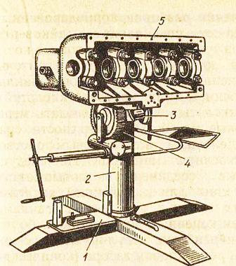
Rice. 26. Universal stand OPR-989 for disassembling and assembling the engine.
1) - Base; 2) - Pipe; 3) - Shaft of rotation; 4) - Worm gear; 5) - Cylinder block.
WITHstart assembling the cylinder block: you need to install bushings and a camshaft, pusher bushings and pushers, oil seals and decompressor rollers, oil pipes. Then you should once again blow through the oil passages in the block with compressed air and install the idler pin, pins and other parts.
V the block is laid with a crankshaft with main bearings, then the cylinder liners, a connecting rod-piston set, a rear beam and a flywheel, an oil pump and a crankcase, a cylinder head, a turbocharger and a rocker mechanism, fuel equipment, filters and pipelines, intake and exhaust manifolds, a water pump are installed and fan, gearbox, starting motor and clutch in a sequence that depends on the design of the engine.
Installing the crankshaft. It is recommended to first assemble and tighten the main bearings without a shaft. The tightening torque of the nuts for YaMZ-238NB engines is 422-460 Nm for the main bolts; adjacent 98-118 N.m .; A-01 and A-41 - 410-440; type SMD - 200-220 N.m (bolts SMD-60 - 160-180 N.m); D-37M - 140-160 N.m; ZMZ-53A - 110-120 N.m; ZIL-130 - 110-130 N.m for the front and 80-100 N.m. for the rest of the bearings. Measurements determine their ovality, taper, oil gap and displacement of the upper insert relative to the lower one. In order to provide an 80% resource, during overhaul, the clearances in the main bearings are not more than: 0.156 mm - SMD-60, 0.160 mm - A01M; 0.180 mm - A-41; 0.120 mm - D-37M; 0.08 mm - ZMZ-53A; 0.065 mm - ZIL-130; 0.130 mm - YaMZ-238NB.
TOLubricate the shaft journals with a thin layer of oil, install the spacer half rings, then lay the crankshaft. First, the middle main bearing is evenly tightened in two or three steps. If the shaft turns easily by the bolt in the flange, then the remaining bearing caps are tightened evenly. If the shaft turns tight, then it should be removed and the necks should be lubricated with a thin layer of paint. Then you need to re-lay the shaft, turn it, disassemble, inspect - by the ink prints on the liners, determine the cause of the tight turning and eliminate it.
PMoving the crankshaft along the axis, check the axial take-off run with a feeler gauge, which for diesel engines ranges from 0.1-0.4 mm, for automobile engines 0.08-0.25 mm. The axial take-off is regulated by the selection of the thickness of the spacer half rings, the thickness of the shoulder of the mounting bearing, or other devices for engines of this type.
PCorrectly laid shaft should turn from the force of the hand applied to the connecting rod journals.
Installing sleeves in the block. The sleeves, which are installed in the block, must be of the same size group, new or of the same repair size, and in the block without O-rings must be free to rotate.
PAfter installing the O-rings, the sleeves should be pressed into the block using a tool with a hydraulic (pneumatic) press or a wooden block and a hammer. It is not allowed to cut the O-ring when pressing.
PAfter pressing-in, the sleeve should protrude 0.10-0.21 mm above the plane of the block for diesel engines SMD-17, SMD-18; 0.09-0.15 mm for D-240, D-241; 0.07-0.27 mm for D-160; 0.65-0.165 mm for diesel engines of other brands. The difference in the protrusion of the sleeves for one block is not more than 0.05 mm. The protrusion allowed without repair is 0.04 mm (for A-01M and A-41 diesel engines, the protrusion is 0.05 mm).
PWith a pressed-in and fixed head, the ovality and taper of the sleeves on the working area are checked from the side of the crankcase (no more than 0.03 mm is allowed).
PWhen carrying out routine repairs, the sleeves must be installed in the block, turning around the axis by 90 degrees relative to the previous position, in order to increase the subsequent service life due to a decrease in ovality.
Installing the connecting rod and piston kit. The kit and the inner surface of the liner must be lubricated with diesel oil before installation.The locks of the first and second piston rings are located at an angle of 180 degrees relative to each other on the pistons of YaMZ-238NB, SMD-18 diesel engines, and between the second and third - at an angle of 90 degrees. On the pistons of ZMZ-53, SMD-60, A-01M and other engines, the locks are positioned at an angle of 120 degrees to one another. In this case, the locks should not be placed against the axis of the finger.
ShThe atunno-piston set is installed into the block from the side of the cylinder head using a ring compression device. In this case, you should pay special attention to the correctness of its location relative to the block (combustion chamber, slots in the piston skirt, arrows on the piston crown, etc.).
BBolts or nuts of connecting rod bearings are tightened with a torque wrench, maintaining a torque of 240-260 Nm. for diesel engines SMD-60; 196-216 N.m. for YaMZ-238NB, YaMZ-240B; 170-190 N.m. for A-01M, A-41; 140-160 N.m. for D-50, SMD-17, SMD-18 and others; 100-120 N.m. for D-37M, D-144, D-21; 68-76 N.m. for carburetor engines ZMZ-53N; 70-80 N.m. for ZIL-130. In ZMZ-53 engines, when assembling the lower connecting rod head, the protrusion on the cover and the number on the connecting rod must match.
PAfter installing the connecting rods, the crankshaft turning moment should not exceed 50 Nm.
Dthe bottom of the pistons after installing the connecting rod-piston set in position b. m. t. should protrude or sink relative to the plane of the block by the size shown in table 52.
Table 52. The location of the piston crown in relation to the density of the block.
You can ask questions only after registration. Login or register, please.
Please tell me, I want to disassemble the engine. but 41 repairs, something pressure jumps, what features and what you need to pay attention to when disassembling, repairing and assembling the engine, thank you all in advance!
Does the pressure sensor work? It's just that the pressure doesn't jump. It is either always low or normal.
Please tell me, I want to disassemble the engine. but 41 repairs, something pressure jumps, what features and what you need to pay attention to when disassembling, repairing and assembling the engine, thank you all in advance!
Hello colleague, is the pallet crumpled?
Perhaps the intake in the pallet is unscrewed from trembling, I had this.
I will be noted 
Let's take it apart, don't be afraid, here on the forum the guys are normal, they will always tell you if anything. I just bought my own, as I bought the tractor, I didn't even start it, I immediately disassembled it. During the winter I grinded the shaft, bought spare parts, I'll start assembling in two weeks, just for a couple and we will.
The guys will assemble the engine take a photo review what and how 
half empty very interesting to see 
take a photo review what and how
I will try, and then how it goes.
take a photo review what and how
I will try, and then how it goes.
Well I will wait 
Guys tell me what is the difference between the repair kit for the water pump and 41 of the old and new model
The time has come for assembling the engine. First, we clean the block, then thoroughly rinse it with gasoline and blow it with air, rinse the crankshaft in one. We pay special attention to canal flushing.
After flushing the block and the crankshaft, we prepare the sleeves for placing in the block. To do this, we lay out the piston rings on the liners with checking the gaps in the joints. In this case, the STAPRI rings do not shine with stability and the gaps in the entire set are from 0.4 to 0.65, they pass according to tolerances. Next, we mark the liners, pistons and rings on the cylinders so that in the future, when assembling, do not confuse, rinse the sleeves and put on the O-rings, lubricate them and the seats in the block with lithol and insert them into the block. It is better to plant the sleeves by making a simple device from a threaded rod and spacers than to hammer with a sledgehammer.
After planting the sleeves, we prepare other parts for further assembly. My main covers, disassemble the oil pump and check the wear, the balancing mechanism required replacing the bearings, both drives of the NSh-10 and NSh-32 oil pumps also required replacing the bearings. engagement clutch NSh-32, cams burned out.
After planting the sleeves, we prepare other parts for further assembly. My main covers, disassemble the oil pump and check the wear, the balancing mechanism required replacing the bearings, both drives of the NSh-10 and NSh-32 oil pumps also required replacing the bearings. engagement clutch NSh-32, cams burned out.
Tell me where are the numbers on the pistons? also the engine collapsed on the pistons found the number 2k or 2zh, what can this mean? and how much did the whole set of pistons cost you, if not a secret
number 2k or 2zh, what does this mean? and how much did the whole set of pistons cost you, if not a secret
2-This is a piston weight group of 3020-3030 kg, and F is a size group of 129.89-129.91. The price of a set is 12800r. When assembling the engine, a piston of one group is desirable.
number 2k or 2zh, what does this mean? and how much did the whole set of pistons cost you, if not a secret
2-This is a piston weight group of 3020-3030 kg, and F is a size group of 129.89-129.91. The price of a set is 12800r. When assembling the engine, a piston of one group is desirable.
Thank you 
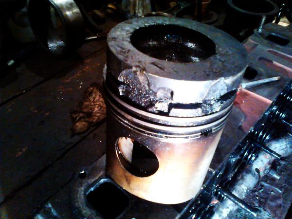
I was thinking of buying a new piston  I disassembled the engine and I felt scared, I will throw off the photo of what kind of piston I had and how it still drove and most importantly did not smoke
Alexander Nikolaevich, you do everything according to Feng Shui 
... Sleeve remover - you can also see it for planting the sleeves in place. I never use a sledgehammer - I insert the sleeves from the effort of my hand, you feel the effort and the rubber rings will not cut off. After planting, I hammer down through a wooden spacer.
This is my handsome 
I insert the sleeves from the effort of the hand, you feel the effort and the rubber rings will not cut off.
To be honest, I didn't even think to try it with my hands, but of course there is a fear.
Hello everyone who can tell you the crankshaft a-41 is China costs 14 tons, and there is a Barnaul shaft costs 24 tons, how do they differ? And can I put Chinese? what do you think
And can I put Chinese? what do you think
And what about the old one, it can polish it. Chinese is roulette. There are no good reviews about them.
And can I put Chinese? what do you think
And what about the old one, it can polish it. Chinese is roulette. There are no good reviews about them.
on the root there are bullies, and the inserts were already p3 to sharpen, I think there is no sense, but about Barnaul, what do you think?
inserts already stood p3 sharpening I think there is no sense, but about Barnaul, what do you think?
There is still one more repairs left, and you can grind them. And Barnaulsky is their own shaft, all the engines run on them. But when replacing the shaft, it is necessary to balance with the flywheel. I had the experience of installing the shaft without balancing, after assembling the motor at the first start, a terrible vibration went, but I did not want to disassemble the motor, I got out of the situation by welding pieces of reinforcement onto the basket using a scientific poke method, though it took two days. After that I always drive for balancing.
inserts already stood p3 sharpening I think there is no sense, but about Barnaul, what do you think?
There is still one more repairs left, and you can grind them. And Barnaulsky is their own shaft, all the engines run on them. But when replacing the shaft, it is necessary to balance with the flywheel. I had the experience of installing the shaft without balancing, after assembling the motor at the first start, a terrible vibration went off, but I did not want to disassemble the motor, I got out of the position by welding pieces of reinforcement onto the flywheel by poking, though it took two days. After that I always drive for balancing.
I didn't think about balancing. 
balancing won't work in my city, I wanted to balance the shaft with 66 gas, so they told me not to balance all machines were sold
The engines are assembled in three stages: vertical position with the crankcase up, when the crankshaft is laid; horizontal position - for installing the main assembly units and parts; vertical position with crankcase down - during final assembly and completing. For individual assembly of engines, a universal stand USD-3 or a special stand for assembling engines D-108 and D-160 is used (Fig. 107).In specialized repair plants, engines are assembled on a production line.
Rice. 107. Stand for disassembly and assembly of D-108 and D-160 engines:
1 - frame, 2 - wheel, 3 - lower sector, 4 - swing bolt, 5 - upper sector, 6 - plate, 7 - roller, 8 - retainer
Engines are assembled in the following order: they put the crankshaft in the main bearings, install the cylinder liners, the connecting rod-piston group, the timing mechanism, the rear beam and flywheel, the oil pump and crankcase, the cylinder head, fuel equipment, filters and pipelines, the intake and exhaust manifolds, water pump and fan, reducer and starter motor.
It is recommended to install the crankshaft in this sequence. Check and complete the shaft with main bearings. If the liners cannot be bored and correspond to the given size of the shaft journals, they are laid in the block bed, the main bearings are assembled and tightened. Lay the crankshaft and check its installation according to the technical conditions for repair.
The admissible values of the clearances in the main bearings without repair with the normal dimensions of the crankshaft journals for tractor engines are: for D-108 and D-160 - 0.35 mm; for all others - 0.24-0.30 mm.
After checking the dimensions and determining the clearances, the bearing caps are removed, the main journals of the shaft are lubricated with a thin layer of oil and the shaft is lowered onto the liners installed in the block.
The tightening torque of the nuts of the main bearings of the D-108 engines is 370-420 Nm; A-01M, A-41 - 410-440; D-65, D-240 - 220-260 and SMD-14-200-220 Nm. First, tighten the middle main bearing and try to turn the crankshaft by hand using the bolt in the flywheel flange. If the shaft turns easily, gradually tighten the remaining bearing caps. The axial run of the crankshaft is checked by moving it along the axis with a crowbar and the end clearance is measured in the extreme position. The axial run of the crankshaft for D-108 engines is 0.1-0.5 mm; SMD-14-0.2-0.4; A-01M and A-41—0.1—0.35 mm.
A correctly laid shaft should be able to turn with the force of the hand applied to the flywheel bolt or connecting rod journals.
The connecting rod-piston group is installed into the block from the side of the cylinder head, using devices for compressing the rings. Tighten the connecting rod bearing nuts with a torque wrench with the following tightening torque: for SMD-14 engines — 140—160 Nm; A-01M, A-41 —160—180; D-108 - 140-150 Nm.
The permissible axial run of the lower connecting rod head without repair is 1 mm. After installing the rear beam and seal housing, install the flywheel. The runout of the flywheel after being secured to the crankshaft should not exceed 0.3 mm.
A-41 piston engine is born more
Was lying in a military warehouse in conservation, so the engine as such was not working.
All rubber products were replaced with new ones.
The fuel equipment was overhauled, it was tuned for the engine modification, all the engine pistons (liner, piston, rings, fingers) were replaced with new Kostroma kits.
The crankshaft is polished, new liners have been replaced, a starter and clutch discs are included.
We give a guarantee for three months after the sales contract is signed.
If desired, we can install the engine, or we can perform rolling on a rolling machine.
The price is negotiable, discussed individually.
There are also many other engines available, for example, YaMZ 236, SMD 31, D260 and so on.
Video piston engine A 41 channel Artem Ivanov
Our company sells spare parts for various types of special equipment, trucks and agricultural equipment of domestic and foreign production, including spare part and engine i AMZ A-01, A-41, D-442 ... One of the directions of the enterprise's work is the repair and maintenance of engines, transmissions, steering, braking systems, running gear, hydraulic and electrical equipment. Working with us, you are guaranteed to receive an individual approach and expert advice, as well as high-quality spare parts and components at the lowest prices.
Troubleshooting and disassembly of the engine Altai
motor plant A-01, A-41, D-442
Troubleshooting of the AMZ A-01, A-41, D-442 engine is carried out in the process of disassembling the engine, by external inspection of units and mechanisms and rejection of worn out and defective parts that are definitely subject to replacement.
Dismantling of the engine AMZ A01, A41, D442 v is performed at the stand. When disassembling the engine, the engine is troubleshooting - the parts are laid out in groups:
- Ÿ suitable for installation on an engine.
- Ÿ parts requiring repair.
- Ÿ unusable.
At disassembling the engine AMZ A-01, A-41, D-442 it is prohibited to use chisels, crowbars, levers. It is not recommended to use adjustable wrenches when disassembling the engine; in the absence of a wrench of the required size, use gaskets between the jaws of the wrench, as this can lead to the tearing of the edges of the bolts and fasteners.
Disassembly and troubleshooting of the engine AMZ A01, A41, D442 is performed in the following order:
-
The impeller and fan belt are removed.
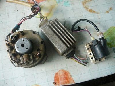
The drives and rods are disconnected, and the nuts and bolts of the generator, carburetor, magneto, starter and starting engine are loosened, then the listed units are removed from the engine.
The high and low pressure fuel wires are disconnected and removed, the air cleaner tubes, bracket and air cleaner are removed.
The fuel filters of fine and coarse cleaning, the oil filter and the housing gasket are removed.
The intake and exhaust manifolds are removed, the plug is removed from the engine sump, the water pipe is removed.
Turning over for further disassembly engineAMZ A-01, A-41, D-442 sump up, the sump with a cork gasket is removed.
Further it is produced disassembly of the engine A01, A41, D442 on knots and details. All details after disassembling the engine are marked, washed and subjected to the final engine troubleshooting AMZ A01, A442 - measurements of the wear of parts are made, based on the results of which a decision is made on the suitability of parts for reuse or restoration.
We provide services for overhaul and restoration of engines for agricultural and special equipment, as well as trucks from leading domestic and foreign manufacturers. All engine repair work is carried out in a workshop using high-tech equipment by our experienced repair technicians. Onsite visits to customers are also possible. We will carry out disassembly of the engine, fault detection and washing, replacement of worn out parts, grinding them in, and, importantly, testing at the stand with subsequent adjustment, painting and installation on the car. Thanks to established cooperation with leading manufacturers and suppliers, we are able to offer not only repairs, but also the sale of original spare parts and components at the lowest prices. ( Go to the engine spare parts catalog AMZ A-01, A-41, D-442)
To purchase spare parts, please call:
A lot of useful information for owners of BMW 5 models can be found on the BMW Automotive Forum Malfunctions, maintenance, repair and operation.
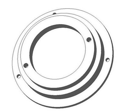
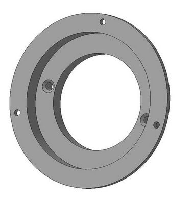
The A-41 engine is equipped with balancing mechanism inertial forces acting in the vertical plane. Balancing mechanism (Figure 1) consists of two weights rotating in opposite directions. The rotational speed of the weights is twice the rotational speed of the crankshaft. The centers of gravity of the weights are directed simultaneously in one direction during rotation. Weights are cast together with axles, which are pressed into gears 2. In the body balancing mechanism Cylindrical roller bearings are installed, in which the axes of the weights rotate. Toothed ring 4, which is mounted on the middle part of the crankshaft near the third main journal, drives the gear to rotate.
Picture 1. Balancing Mechanism Parts: a - device; b - diagram of forces; в - installation of gears according to marks; 1 - case; 2 - gear; 3 - oil line to the oil cooler; 4 - toothed ring of the balancing mechanism drive; 5 - an adjusting gasket; 6 - cargo.
As a result of the rotation of the weights, centrifugal forces Pc appear, which are decomposed into two components - horizontal and vertical forces. Horizontal forces act in opposite directions, thereby balancing each other. The vertical forces add up and add up to Vs. The sum of the vertical forces vertically balances the sum of the inertial forces Ri in all four cylinders.
Installation balancing mechanism on the A-41 engine is carried out with the piston position of the first cylinder at top dead center. The gears should be installed according to the marks applied to their teeth and grooves when the weights are located below.
The engines are assembled in three stages: vertical position with the crankcase up, when the crankshaft is laid; horizontal position - for installing the main assembly units and parts; vertical position with crankcase down - during final assembly and completing. For individual assembly of engines, a universal stand USD-3 or a special stand for assembling engines D-108 and D-160 is used (Fig. 107). In specialized repair plants, engines are assembled on a production line.
Rice. 107. Stand for disassembly and assembly of D-108 and D-160 engines:
1 - frame, 2 - wheel, 3 - lower sector, 4 - swing bolt, 5 - upper sector, 6 - plate, 7 - roller, 8 - retainer
Engines are assembled in the following order: they put the crankshaft in the main bearings, install the cylinder liners, the connecting rod-piston group, the timing mechanism, the rear beam and flywheel, the oil pump and crankcase, the cylinder head, fuel equipment, filters and pipelines, the intake and exhaust manifolds, water pump and fan, reducer and starter motor.
It is recommended to install the crankshaft in this sequence. Check and complete the shaft with main bearings. If the liners cannot be bored and correspond to the given size of the shaft journals, they are laid in the block bed, the main bearings are assembled and tightened. Lay the crankshaft and check its installation according to the technical conditions for repair.
The admissible values of the clearances in the main bearings without repair with the normal dimensions of the crankshaft journals for tractor engines are: for D-108 and D-160 - 0.35 mm; for all others - 0.24-0.30 mm.
After checking the dimensions and determining the clearances, the bearing caps are removed, the main journals of the shaft are lubricated with a thin layer of oil and the shaft is lowered onto the liners installed in the block.
The tightening torque of the nuts of the main bearings of the D-108 engines is 370-420 Nm; A-01M, A-41 - 410-440; D-65, D-240 - 220-260 and SMD-14-200-220 Nm. First, tighten the middle main bearing and try to turn the crankshaft by hand using the bolt in the flywheel flange. If the shaft turns easily, gradually tighten the remaining bearing caps. The axial run of the crankshaft is checked by moving it along the axis with a crowbar and the end clearance is measured in the extreme position. The axial run of the crankshaft for D-108 engines is 0.1-0.5 mm; SMD-14-0.2-0.4; A-01M and A-41—0.1—0.35 mm.
A correctly laid shaft should be able to turn with the force of the hand applied to the flywheel bolt or connecting rod journals.
The connecting rod-piston group is installed into the block from the side of the cylinder head, using devices for compressing the rings. Tighten the connecting rod bearing nuts with a torque wrench with the following tightening torque: for SMD-14 engines — 140—160 Nm; A-01M, A-41 —160—180; D-108 - 140-150 Nm.
The permissible axial run of the lower connecting rod head without repair is 1 mm. After installing the rear beam and seal housing, install the flywheel. The runout of the flywheel after being secured to the crankshaft should not exceed 0.3 mm.
TO Category: - Maintenance of road cars
Hello! I have a problem with the SMD -22 engine.We have purchased a Sk-5 Niva combine. Block SMD-22 (vibito on the block), which head I do not know, they recently replaced it, a turbine. It initially worked uncleanly (sometimes white smoke slipped through). The engine was in need of repair. The first step was to adjust the fuel and engine overhaul. But strangely enough, the problem did not disappear. It was heard that the engine was slightly troit white smoke slipped from the exhaust. I removed the exhaust manifold and started the engine. Cylinders 1, 3,4 work and the second one simply gives off white smoke of non-combustible fuel.
Changed the injectors, the problem is the same.
Put another fuel pump nothing has changed.
Then I started adjusting the fuel injection angle. When I put it a little later, the smoke from the second cylinder was even more and the engine was losing power. When I rearranged the hazel grouse aside + earlier, the second cylinder gradually began to work. The earlier the 2 cylinder worked more, but at first 1 and 4 cylinders stopped working then almost immediately and 3. I think it means I messed up with the marks when I assembled the engine. Disassembled everything is normal. Replaced the camshaft all in place. The clearance between the valves was adjusted 20 times, but the problem did not go away.
Little is written in this thread https://my.housecope.com/wp-content/uploads/ext/967/forum/obshchie-voprosy-po-sel-2. but it was my question that I could not find an answer
Advise what it can be and how to solve the problem?
Last visit: 2 hours 21 minutes ago
Registration: 09.11.2010 - 20:53
Perhaps the valve is not tight, or water is entering the cylinder, or, unlikely, a high pressure pipe.
Last visit: 6 months 1 week ago
Registration: 04.12.2010 - 00:21
Perhaps the valve is not tight, or water is entering the cylinder, or, unlikely, a high pressure pipe.
The valves have been repeatedly checked and lapped. The valves are filled with a wide working part. No water enters the cylinder. The tube is excluded, since when the injection angle is changed, the second cylinder starts to work well. And so I removed and checked all the tubes and nozzles.
Last visit: 2 hours 21 minutes ago
Registration: 09.11.2010 - 20:53
Most likely there is some kind of trifle that you will not immediately think about it, but she hollows. In my practice, there were several cases when, because of a trifle, I made a move several times and racked my brains for a whole year.


| Video (click to play). |
I ask for advice, set the adjustment of the moment sequence of actions.


