In detail: gas engine 53 DIY repair from a real master for the site my.housecope.com.
This video shows how to do it yourself engine repair Gas 53... For almost two hours, the author of the video reveals step by step the procedure for assembling the engine, starting with the preparatory work and ending with the unit completely ready for installation on the car.
The first preparatory step is a complete wash of all engine parts. The author tells in detail about the necessary materials and tools for the high-quality performance of this work.
The next preparatory stage is the installation of small parts such as bushings, bearings, oil seals, studs, plugs, etc. In the course of the assembly, it tells about the possible nuances that arise when installing certain parts. Also, this block describes the procedure and features of installing the crankshaft and camshaft, aligning the drive gears according to special marks.
Next, the author proceeds to describe the assembly of the crank and gas distribution mechanisms. The order of installation of connecting rods, pistons with rings, intake and exhaust valves is shown in stages. At this stage, the oil pump is installed and the head bolts are screwed in. During the assembly process, the author of the video tells the diagram of the movement of oil in the cylinder block. The last, important action is the assembly and adjustment of the gas distribution mechanism, namely the installation of pushers, rocker arms, and adjustment of the gaps.
After that, the installation of various attachments on the engine is demonstrated, such as a pump, thermostat, oil filter, pressure gauge, connecting pipes and much more. As a result, the engine is assembled and ready to be installed on the vehicle.
| Video (click to play). |
To neglect the repair of the Gas 53 engine, you must always maintain a good technical condition of the engine and its constant readiness for operation, as well as eliminate the causes that accelerate the wear of its parts, use the recommended gasoline, oil and lubricants.
To neglect the repair of the Gas 53 engine, you must always maintain a good technical condition of the engine and its constant readiness for operation, as well as eliminate the causes that accelerate the wear of its parts, use the recommended gasoline, oil and lubricants.
Periodically check the attachments of the cylinder heads to the cylinder head and clean the pistons and combustion chamber surfaces from carbon deposits. Tighten, if necessary, the HZ fastening nuts. Before that, drain the coolant from the cooling system.
Then, in order to eliminate the mutual influence of tightening one head on the other, the fastenings of the inlet pipe to the HZ are loosened. Then tighten the nuts securing the head to the cylinder head with a torque of 73-78 with a torque wrench. See Figure 1 for the sequence of tightening the nuts securing the head to the cylinder head.
It is recommended to tighten the heads during the first three maintenance operations, and then to perform them after each TO-2. Using the recommended gasoline and oils and observing the engine's temperature regime, then you will not need to repair the Gas 53 engine soon, if it is required at all, and carbon deposits will not be significant and will not affect the performance of the engine.
If these conditions are not followed, a carbon layer may appear in the engine, which causes detonation, a decrease in power and, as a rule, an increase in fuel consumption. To get rid of carbon deposits, dismantle the intake pipe of the HZ and clean the piston bottoms and surfaces of the combustion chambers.
If the engine "eats" leaded gasoline, then the carbon deposit is moistened with kerosene before cleaning, so that it does not get into the respiratory system. Since there is a lot of strong poison in the cinder. The rapid re-formation of carbon deposits indicates a malfunction of the engine and the repair of the Gas 53 engine is necessary.
To increase the engine life before the first overhaul during operation, it is recommended to replace the piston rings and crankshaft main bearing shells. The latter must be replaced when the oil pressure on a warm engine drops below 100 kPa at a crankshaft speed of 1200 min, which corresponds to a forward speed of 30-35 km / h.
In this case, the oil cooler must be turned off. When replacing the main bearing shells, the connecting rod bearing shells are also inspected, they are replaced only if necessary. Simultaneously with the replacement of the main bearing shells, the cavities of the crankshaft connecting rod journals are cleaned.
This operation must be carried out very carefully, since the remaining dirt that has not been removed will be carried away by the oil to the connecting rod bearings, which will lead to scoring and wear.
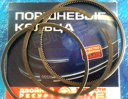
After cleaning the cavities, the plugs are tightly wrapped. Piston rings are replaced if the oil consumption for waste exceeds 400 grams per 100 kilometers. Install the required set of rings, consisting of the first non-chromed cast iron compression ring, the second from a set of steel discs and a set of oil scraper rings with non-chrome steel discs.
When replacing the rings, remove the unworn protruding band in its upper part on the cylinder liners (scrapers or other tool). Simultaneously with replacing the piston rings, the cylinder heads and piston crowns are cleaned from carbon deposits, and the valves are rubbed against the head seats.
The gas distribution mechanism requires periodic inspection and, if necessary, adjusting the valve clearances, cleaning the valves from carbon deposits and lapping them to the seats. The clearances are checked with the engine idling with the push rod fully lowered.
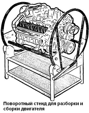
To assemble the engine, as well as to disassemble it, the engine block assembly with the clutch housing is fixed on the stand (see Fig. 11 of section "2.3.1. GAZ-53A and GAZ-66. Engine disassembly").
All engine parts are sized before assembly. (Table 4 see section "2.5.1. GAZ-53A and GAZ-66. Dimensions of the main parts, clearances and tightness in engine interfaces"). rinse thoroughly, blow with compressed air and wipe with clean napkins. All threaded connections (pins, plugs, fittings, etc.), if they were turned out during disassembly or were replaced with new ones, must be placed on red lead or lead whitewash diluted with natural drying oil. Permanent connections (plugs of the block and cylinder heads) are placed on nitro lacquer.
The following are not allowed to be installed on a repaired engine:
- used cotter pins and cotter wires;
- spring washers that have lost their elasticity;
- extended thread bolts and studs;
- nuts and bolts with worn edges;
- parts with more than two nicks or dents on the thread or torn threads;
- damaged gaskets.
Assemble the engine in the reverse order of disassembly.
Below are specific recommendations and additional requirements for engine assembly.
At replacement of cylinder liners before installation the liner is selected according to the socket in the cylinder block.
The liners are selected using an accurate metal ruler and a set of probes as follows: the liner, installed in its place in the cylinder block without gaskets, must sink against the cylinder block mating surface. The ruler is installed on the mating surface, and the probe is inserted into the gap between the ruler and the end of the sleeve (Fig. 23).The thickness of the gasket is chosen so that after installing the liner with the gasket, it will rise above the surface of the cylinder block in the range of 0.02 - 0.09 mm.
Rice. 23. Determination of the position of the liner in the cylinder block
Sealing gaskets are produced in various thicknesses: 0.3; 0.2; 0.15 and 0.1 mm. Depending on the gap, one or another gasket is put on the cylinder liner, sometimes the required value is obtained by a set of gaskets of various thicknesses.
After installation in the cylinder block, the liners are secured with clamping bushings (see Fig. 13 of section "2.3.1. GAZ-53A and GAZ-66. Dismantling the engine").
An asbestos cord impregnated with an oil-graphite mixture is used as a rear oil seal on engines. A cord with a length of 140 mm is laid in the sockets of the cylinder block and the gland holder. Using the device, the cord is crimped in its sockets with light hammer blows, as indicated in Fig. 24. Without removing the device, cut the ends of the cord flush with the plane of the gland holder connector. The cut must be even, no loose ends and uneven cut are allowed.
Rice. 24. Laying the crankshaft rear oil seal in the oil seal holder
Tighten the nuts securing the main bearing caps (torque 11-12 kgm). After tightening and splitting the nuts of the main bearing caps, the crankshaft should rotate easily with little effort.
Fig. 25. Pressing on the crankshaft gear
After pressing the crankshaft gear (Fig. 25) using a puller and a thrust sleeve, check the axial clearance of the crankshaft, for which press the crankshaft to the rear end of the engine and use a feeler gauge to determine the gap between the end of the rear thrust bearing washer and the end of the front main journal of the crankshaft (fig. 26). The gap should be between 0.075 - 0.175 mm.
Rice. 26. Checking the axial clearance
When assembling the parts of the connecting rod-piston group, the following requirements must be observed.
- Piston fingers are selected to the connecting rods so that at room temperature (+ 18 ° C) a slightly lubricated finger smoothly moves in the connecting rod bore under a light thumb.
- Before assembly, the pistons are heated in hot water to + 70 ° C.
Pressing a pin into a cold piston is not allowed, as this can lead to damage to the surfaces of the piston pin bore holes, as well as to deformation of the piston itself.
Rice. 27. Connecting the connecting rod to the piston:
a - for installation in the 1st, 2nd, 3rd and 4th cylinders; b - 5,6, 7 and 8th cylinders;
1-inscription on the piston; 2-number on the connecting rod; 3-mark on the connecting rod cover
When assembling, connecting rods and pistons are oriented as follows:
- for pistons of the first, second, third and fourth cylinders, the inscription on the piston and the number stamped on the connecting rod should be directed in opposite directions, and for the pistons of the fifth, sixth, seventh and eighth cylinders - in one direction (Fig. 27).
- The piston pin retaining rings are installed in the grooves of the piston bosses so that the bend of the antennae is directed outward.
- Piston rings are selected according to the liners in which they will work. The gap measured at the junction of the ring laid in the sleeve should be within 0.3 - 0.5 mm for compression and oil scraper rings, chrome-plated is installed in the upper piston groove, and in the second - a tin-plated compression ring with a groove on the inner side to the bottom.
Before installing in the cylinder liners, the joints of the piston rings should be positioned at an angle of 120 ° to each other, and protective brass caps should be put on the connecting rod bolts to avoid accidental damage to the surface of the connecting rod journals.
When installing pistons in cylinder liners, make sure that the inscription on the piston is directed towards the front end of the cylinder block. Tighten the connecting rod bolt nuts (torque 6.8 - 7.5 kgm) and lock.
After pressing the gear onto the camshaft (Fig. 28), check the axial clearance between the thrust flange and the end of the camshaft gear with a feeler gauge. The gap should be between 0.08 - 0.2 mm.
Rice. 28.Pressing the gear onto the camshaft
- Set the piston of the 1st cylinder to the position of the top dead center (TDC) in the compression stroke.
- Insert the breaker-distributor drive into the hole in the cylinder block so that the slot in the drive shaft is directed along the engine axis and shifted to the left, counting along the direction of the vehicle.
- Fasten the drive housing with a holder and a nut so that the bracket with a threaded hole for attaching the switch-distributor is directed backwards and turned 23 ° to the left of the longitudinal axis of the motor, as shown in Fig. 29.
- Before installing the breaker-distributor on the engine, check the gap in the breaker contacts and, if necessary, adjust it. The contact gap should be between 0.3 and 0.4 mm.
- Using the octane-corrector nuts, turn the body of the breaker-distributor so that the arrow is set to zero scale division.
- Turn the distributor rotor so that it faces towards the terminal of the first cylinder. The terminal of the first cylinder on the ignition distributor cover is marked with the number "1".
Put on the distributor cover with wires and connect the latter to the spark plugs in the order of operation of the engine cylinders (1 - 5 - 4 - 2 - 6 - 3 - 7 - 8). The ignition order is cast on the engine intake manifold.
Rice. 29. Installation of the drive of the breaker-distributor
One of the most legendary engines of the Soviet car industry can rightfully be considered the GAZ 53 or ZMZ 511. It has served the people for many decades with faith and truth. Until our time, many of the separated corners of the Soviet Union operate this "not kill" power unit, and the GAZ plant still produces spare parts for it.
The history of the GAZ 53 internal combustion engine began back in 1959, when, by order of the Communist Party, they began to develop an engine that was supposed to replace the outdated GAZ 51. So, for the first time, the GAZ 53 car was equipped with a power unit number 511 back in 1961, and this continued until 1993.
During the production of the car, quite a lot of modifications and experimental models were made. So, motors were installed - GAZ-53F, GAZ-53A, GAZ-53-12 and ZMZ-511. Also, engine models were developed that were not massively installed, but found application in folk tuning. Among such representatives are UAZ with a GAZ 53 engine and a Gazelle with a GAZ 53 engine.
In parallel with the 53rd, the Gorky plant was producing a hybrid - GAZ 52. It was a six-cylinder engine, which was supposed to be something in between the GAZ 51 and 53. The receiver of the 53rd was GAZ 3307, which was already equipped with power units from MMZ and YaMZ. In 1997, the ZMZ-53 production line ceased to exist, and only one workshop remained for the manufacture of spare parts for the engine.
At the time of its birth, the GAZ 53 engine was considered strong enough, since it had a large amount of horsepower. In more detail, it is worth analyzing the technical characteristics in the table:
All GAZ 53 engines from the factory were equipped with a 4-speed gearbox. And only in 1987, a 5-speed gearbox was developed for the ZMZ-511 engine, which improved tractive power and torque.
Any car, especially a Soviet one, has been tuned at least once. So, the 53rd third after the Volgovsky (GAZ 24) and Uazovsky (UMZ-417) power units is the most popular in revision, since it has a simple design and is easy to innovate. But, nevertheless, he gained great popularity due to the introduction of the engine on other cars. So many times, you can find a UAZ with a GAZ 53 engine.
For those who love the forced GAZ 24 or 3102, they can easily install the ZMZ 511. You can often see the Volga rushing with the GAZ 53 engine. ...
Thus, the installation of the ZMZ 511 on the GAZ 24 should be approached with seriousness and all the nuances should be fully calculated, since the internal potential is large enough, but not everyone has enough intelligence to complete it.
Maintenance of a car with a GAZ 53 engine is quite simple and not troublesome, especially when it is installed on a GAZ 24. The engine, of course, we consume about 10 liters of oil, but at the same time its resource is about 250,000 km of run with regular maintenance ...
So, it is worth describing the main stages of maintenance of the power unit:
- TO-1 - oil change, fuel filter, valve mechanism tightening.
- TO-2 - changing the oil, the fuel filter, tightening the valve mechanism, replacing the fuel filter and valve cover gaskets.
- TO-3 - changing the oil, fuel filter, tightening the valve mechanism, replacing the timing kit, replacing spark plugs, high-voltage wires.
- TO-4 - changing the oil, fuel filter, tightening the valve mechanism, replacing the fuel filter, valve cover gaskets, cylinder head gaskets and oil pan.
The difference in mileage between maintenance is 12,500 km. With proper and regular maintenance, the engine is capable of reaching about 300,000 - 350,000 km of run. After a major overhaul, the technical service card is changed and maintenance must be carried out more often.
Repair of ZMZ-511 is carried out according to flow breakdowns. Since the power unit is quite reliable, it can rightfully be considered the standard of endurance. But, even the best engines have their own resource and need to be repaired.
The engine from the GAZ 53 does not break down over trifles and this immediately leads to a major overhaul, which in many cases costs like a new engine. That is why many motorists practice repairing the GAZ 53 engine with their own hands. Consider the main technological process of overhaul of the ZMZ-53 power unit.
What procedures need to be performed and passed:
- Washing the motor.
- Disassembly. At this stage, the engine undergoes a total analysis into spare parts to determine which parts are damaged, how much damage has been done to the block and crankshaft, the state of the block heads, piston group and block heads. Also, minor parts are subjected to diagnostics, namely: the oil and water pump, without fail the clutch and others.
- Diagnostic process. Only three main parts are involved here - the block (chambers where combustion occurs), the crankshaft (for maintainability) and the cylinder head (the state of the gas distribution mechanism).
- The process of measuring and sizing. The crankshaft is bored. So, for this part there is a size chart:
To assemble the engine, as well as to disassemble it, the engine block assembly with the clutch housing is fixed on the stand (see Fig. 1).
Before assembly, all engine parts are sized, washed thoroughly, blown with compressed air and wiped with clean napkins. All threaded connections (pins, plugs, fittings, etc.), if they were twisted during disassembly or were replaced, must be placed on red lead or lead whitewash diluted with natural drying oil.
To be installed on a repaired engine not allowed:
- used cotter pins and cotter wires;
- spring washers that have lost their elasticity;
- bolts and studs with extended thread;
- nuts and bolts with worn edges;
- parts with more than two nicks or dents on the thread, or torn threads;
Assemble the engine in the reverse order of disassembly.
Below are specific recommendations and additional requirements for engine assembly.
When replacing cylinder liners, before installing, the liner is selected according to the socket in the cylinder block.
Liners are selected using an accurate metal ruler and a set of probes as follows:
- the liner, installed in its place in the cylinder block without gaskets, must sink against the cylinder block mating surface.
The ruler is installed on the mating surface, and the probe is inserted into the gap between the ruler and the end of the sleeve (Fig. 2).
The thickness of the gasket is chosen so that after installing the liner with the gasket, it will rise above the surface of the cylinder block within the range of 0.02-0.09 mm.
Sealing gaskets are available in various thicknesses:
0.3; 0.2; 0.15 and 0.1 mm. Depending on the gap, one or another gasket is put on the cylinder liner, sometimes the required value is obtained by a set of gaskets of various thicknesses.
After installation in the cylinder block, the liners are secured with clamping sleeves (see Fig. 3).
As a rear oil seal on engines, an asbestos cord impregnated with an oil-graphite mixture is used. A cord with a length of 140 mm is laid in the sockets of the cylinder block and the gland holder. Using the device, the cord is crimped in its sockets with light hammer blows, as indicated in Fig. 4. Without removing the device, cut the ends of the cord flush with the plane of the gland holder connector. The cut must be even, no loose ends and uneven cut are allowed.
When assembling the crankshaft with flywheel and clutch, the following requirements are met.
The flywheel mounting nuts are tightened, providing a torque of 7.6-8.3 kgm.
When assembling the clutch, the driven disc is mounted with a damper to the pressure plate and centered on the crankshaft bearing (the gearbox drive shaft can be used as a mandrel).
Marks "O", embossed on the casing of the pressure plate and the flywheel near one of the holes for the casing mounting bolts, must be aligned.
The crankshaft, flywheel and clutch assembly must be dynamically balanced. Allowable imbalance is 70 Gsm.
When balancing, remove excess weight from the heavy side by drilling the flywheel metal at a distance of 6 mm from the ring gear with a drill 8 mm in diameter to a depth of no more than 10 mm.
If the imbalance of the assembled shaft exceeds 180 Gsm, the shaft is disassembled and each part is balanced separately. Flywheel imbalance should not exceed 35 Gsm; imbalance of the pressure plate assembly with the casing - 36 Gsm; The imbalance of the driven disk is 18 Gsm.
Main bearing caps set so that the fixing protrusions of the liners are on one side, and the numbers or marks embossed on the covers correspond to the numbers of the beds. When installing the front cover, it is necessary to ensure that the locking tab of the rear thrust bearing washer enters the groove of the cover, and that no steps are formed between the end of the cover and the end of the cylinder block.
Tighten the nuts securing the main bearing caps (torque 11-12 kgm). After tightening and splitting the nuts of the main bearing caps, the crankshaft should rotate easily with little effort.
After pressing the crankshaft gear (Fig. 5) using a puller and a thrust sleeve, check the axial clearance of the crankshaft, for which press the crankshaft to the rear end of the engine and use a feeler gauge to determine the gap between the end of the rear thrust bearing washer and the end of the front main journal of the crankshaft (fig. 6). The gap should be between 0.075 - 0.175 mm.
When assembling the parts of the connecting rod-piston group, the following requirements must be observed.
Piston pins are selected to the connecting rods so that at room temperature (+18 0 C) a slightly lubricated finger smoothly moves in the connecting rod hole under a slight effort of the thumb.
Before assembly, the pistons are heated in hot water to +70 0 С.
Pressing a pin into a cold piston is not allowed, as this can lead to damage to the surfaces of the piston pin bore holes, as well as to deformation of the piston itself.
Connecting rods and pistons when assembling, they are oriented as follows: for the pistons of the first, second, third and fourth cylinders, the inscription on the piston "in front" and the number stamped on the connecting rod should be directed in opposite directions, and for the pistons of the fifth, sixth, seventh and eighth cylinders - in one side (fig. 7).
The piston pin retaining rings are installed in the grooves of the piston bosses so that the tendril bend is directed outward.
Piston rings are selected according to the sleeves in which they will work. The gap, measured at the joint of the ring, laid in the sleeve, should be in the range of 0.3-0.5 mm for compression and oil scraper rings. In the upper piston groove, a chrome-plated one is installed, and in the second - a tin-plated compression ring with a groove on the inner side to the bottom.
Before installing the piston ring joints in the cylinder liners, place the piston ring joints at an angle of 120 ° to each other, and protective brass caps should be put on the connecting rod bolts to avoid accidental damage to the connecting rod journal surface.
When installing pistons in cylinder liners, make sure that the inscription on the piston "in front" is directed towards the front end of the cylinder block. Tighten the connecting rod bolt nuts (torque 6.8 - 7.5 kgm) and lock.
After pressing the gear onto the camshaft (Fig. 8), check the axial clearance between the thrust flange and the end of the camshaft gear with a feeler gauge. The gap should be between 0.08 - 0.2 mm.
Sometimes a car breaks down, requiring restoration measures. One of these procedures is the repair of the GAZ 53 engine, which has long expired its warranty period. Without cars, our lives would not only be less intense, but also more boring. In addition, the transportation of goods is one of the priority tasks, which is carried out using road transport. A striking representative of the domestic auto industry is GAZ 53, which is well known to each of us and is used for various types of cargo transportation.
It looks like a classic truck GAZ 53
At the time of its creation, the legendary GAZ 53 car was equipped with two engine options with many modifications. The first of these was the 6-cylinder GAZ 11, which did not find its broad note in this particular car model. In turn, the second version of the ZMZ 53 engine, having a volume of 4.25 liters, was installed much more times. Therefore, today, the GAZ 53 engine is often exactly the ZMZ 53. This engine is a kind of standard for the reliability and durability of an automobile engine.
Zmz 53 engine for gas 53 car
- knock of connecting rod bearings;
- burnout of exhaust valves;
- increased fuel and oil consumption;
- abrasion of piston rings;
- knocking of the upper bushings or pistons;
- burnout of the cylinder block gaskets.
It is these malfunctions that most often lead to engine malfunction, which can cause it to stop completely. Almost all of them are associated with violations of the operation of the unit. So, the abrasion of the piston rings and the appearance of knocking in the connecting rod bearings are the result of neglecting the vehicle operating instructions.
In turn, the burnout of various valves and gaskets is a direct consequence of overheating of the system, and an increase in oil consumption occurs as a result of ignoring preventive measures.
Prevention of the ZMZ 53 engine is a guarantee of maintaining its optimal functionality and is designed to maintain the operation of the device at the proper level.
In addition, similar measures make it possible to timely determine the formation of any serious damage to the motor and eliminate them at the lowest cost.
That is why these procedures are of great importance and prevent the formation of minor faults, the list of which was given above.In general, maintenance of the GAZ 53 engine consists in carrying out the following measures:
- replacement of the lubricant;
- tightening the cylinder heads;
- checking the exhaust manifold mountings;
- control of the amount of coolant;
- adjustment of valves;
- checking the oil level in the system.
Timely implementation of all the above procedures can serve as the key to the successful operation of an automobile engine and guarantee its optimal functionality. Maintenance of the machine has its own subtleties that must be taken into account by all means.
Engine lubrication system Gas 53

