In detail: Toyota 2c diesel engine 2 liters DIY repair from a real master for the site my.housecope.com.
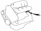
Removal and installation of a timing belt 2C... 1 - right engine support, 2 - washer reservoir, 3 - power steering pump, 4 - power steering pump drive belt, 5 - power steering pump pulley, 6 - timing belt cover No. 2, 7 - gasket, 8 - timing belt, 9 - timing belt guide, 10 - timing belt cover No. 1, 11 - alternator drive belt, 12 - crankshaft pulley, 13 - washer, 14 - right engine support bracket, 15 - right side of engine protection.
1. Remove the right side of the engine guard.
2. Remove the washer fluid reservoir.
3. Remove the power steering pump drive belt.
4. Remove the power steering pump.
a) Disconnect the hydraulic line clamp. ...
b) Remove the power steering pump pulley.
c) Remove the power steering pump with the air bypass hose by unscrewing the 3 mounting bolts.
5. Remove the alternator drive belt.
6. Remove the crankshaft pulley.
a) Install the special tool on the crankshaft pulley.
b) Holding the pulley from turning with a special tool, unscrew the bolt securing the crankshaft pulley.
c) Using a special puller, remove the crankshaft pulley.
7. Remove the right engine mount,
a) Unscrew 1 (2WD) or 2 (4WD) fastening nuts.
9. Remove cover No. 2 of the timing belt by unscrewing 3 nuts and 5 mounting bolts.
10. Remove the timing belt guide.
11. Remove the right engine support bracket by unscrewing the 4 mounting bolts.
| Video (click to play). |
12. Set the # 1 cylinder piston to TDC on the compression stroke.
Align the mark on the camshaft pulley with the cylinder head connector line and the cylinder head cover by turning the crankshaft pulley clockwise.
13. Remove the timing belt. Note: If you intend to reuse the belt being removed, mark the direction arrow of the belt in the direction of rotation of the crankshaft, as well as marks on the pulleys and belt.
a) Using a screwdriver, remove the timing belt tension roller spring.
when removing the spring, do not use pliers, etc.
b) Loosen the tension fastening bolt. foot roller.
c) Remove the timing belt.
14. Remove the camshaft pulley.
a) Holding the pulley from turning with a special tool, unscrew the camshaft pulley mounting bolt.
Note: Do not allow the camshaft to turn to avoid striking the valves with the piston crowns.
b) Using a special tool, remove the camshaft pulley.
15. Remove the roller tensioner.
16. Remove the high-pressure pump drive toothed pulley.
a) Holding the high-pressure pump drive pulley from turning with a special tool, unscrew the pulley fastening nut.
do not use an inertia puller when loosening the nut.
b) Using a special tool, remove the injection pump drive pulley.
17. Remove the idler pulley.
18. Remove the oil pump drive pulley.
a) Holding the oil pump pulley from turning with a special tool, unscrew the pulley retaining nut.
b) Remove the oil pump pulley.
19. Using the special tool, remove the crankshaft toothed pulley.
- During this operation, the crankshaft can turn, and since it is not synchronized with the camshaft, under certain circumstances it can bend the valves.
1 Install the crankshaft toothed pulley.
a) Align the keyway on the pulley with the key on the front g ;; toe of the crankshaft,
b) Using a special mandrel (or a tube of a suitable diameter) and a hammer, fit the toothed pulley 1 onto the crankshaft.
c) Holding the toothed pulley with a special tool, install it and tighten the pulley retaining nut to the specified torque.
2. Install the idler pulley. Torque. 37 Nm
3. Install the injection pump drive toothed pulley.
a) Align the keyway on the pulley with the key on the toe of the injection pump drive shaft.
b) Holding the pulley with a special tool, install it and tighten the pulley nut to the specified torque.
4. Pre-install the idler pulley.
a) Install the tension roller on the cylinder head and hand tighten the roller bracket mounting bolt as follows. so that the roller moves freely.
b) Install and tighten to the specified moment the roller mounting bolt.
c) Check that the idler roller bracket moves freely to the left and right by hand.
5. Install the camshaft pulley.
a) Align the dowel pin hole on the pulley with the pin on the front toe of the camshaft.
b) Holding the camshaft pulley with a special tool, install the mounting bolt together with the washer and tighten it to the specified torque.
6. Align the timing marks on the camshaft pulleys, the injection pump drive shaft and the crankshaft with the corresponding marks.
a) Align the mark on the camshaft pulley with the connector plane of the cylinder head cover and cylinder head.
b) Align the alignment mark (groove) on the crankshaft pulley with the mark on the oil pump housing.
when aligning the marks on the crankshaft and camshaft pulleys, avoid turning the pulleys to avoid collision of the valves with the piston crowns.
c) Align the mark on the injection pump pulley with the mark on the surface of the coolant pump.
7. Install the timing belt.
- Installation is performed on a cold engine.
- When reusing the belt, align the timing marks made when removing the belt and install the timing belt so that the rotation arrow matches the direction of rotation of the crankshaft.
- When installing a new timing belt, check that the numbers and letters of the marking are readable when viewed from the rear of the engine. a) Slide the timing belt onto the pulleys in the following order:
(1) crankshaft toothed pulley,
(3) coolant pump pulley,
(6) the camshaft pulley,
(7) timing belt tensioner.
b) Using a screwdriver, install the tension roller spring.
- Do not use pliers when tightening the spring tension roller.
8. Check if the valve timing is correct.
a) Temporarily install the crankshaft pulley mounting bolt.
b) Turn the crankshaft two turns until the alignment mark on the camshaft pulley aligns with the upper plane of the cylinder head.
turn the crankshaft clockwise only. If the direction of rotation is incorrect, the belt teeth may become disengaged due to a change in the spring tension.
c) Make sure the alignment marks on the other pulleys are aligned as shown in the figure.
If the marks do not match, repeat the procedure from step 6.
d) Remove the crankshaft pulley mounting bolt.
9. Tighten the roller tensioner mounting bolt.
Note: While tightening the bolt, do not move the idler roller bracket.
10. Install the right engine mount bracket by tightening the 4 mounting bolts.
11. Install the timing belt guide as shown in the illustration.
12. Install the cover. No. 1 of the timing belt by tightening the 5 mounting bolts.
13. Install cover No. 2 of the timing belt by tightening 5 bolts and 3 mounting nuts.
14. Install the right engine mount.
a) Install the right engine mount shock absorber by tightening the 3 mounting bolts.
b) Install the shock absorber bracket by tightening the bolts and mounting nuts.
c) Tighten the fastening nuts.
15. Install the crankshaft pulley.
sixteen.Install the power steering pump by tightening the 3 mounting bolts.
17. Install the power steering pump pulley.
18. Connect the hydraulic line clamp.
19. Install the alternator drive belt.
20. Install the power steering pump drive belt
22. Install the right side-engine protection.
23. Check and adjust the injection advance angle.
The engine number is stamped on the cylinder block, the location of the number is shown in the corresponding figure with an arrow.
1. Use fenders, seat covers and floor mats to protect your vehicle from dirt and damage.
2. When disassembling, place the parts in the correct order to facilitate reassembly.
3. Observe the following rules:
a) Before carrying out work on electrical equipment, disconnect the cable from the negative terminal of the storage battery.
b) If it is necessary to disconnect the battery for control check or repair work, be sure to first disconnect the cable from the negative (-) terminal, which is connected to the car body.
c) When carrying out welding work, disconnect the battery and connectors of the electronic control unit.
4. Check reliability and correctness of fastening of couplings and fittings of hoses and wire connectors.
5. Parts not subject to reuse.
a) Be sure to replace the split pins, gaskets, o-rings, oil seals, etc. to new ones.
b) Parts that cannot be reused are marked with “•” in the illustrations.
6. Before working in the spray booth, disconnect and remove the battery and the electronic control unit from the vehicle.
7. If necessary, apply a sealing compound to the gaskets to prevent leaks.
8. Carefully observe all technical conditions regarding the values of the tightening torque of the threaded connections. Be sure to use a torque wrench.
9. Depending on the nature of the repairs being performed, it may be necessary to use special materials and special tools for maintenance and repair.
10. When replacing blown fuses, make sure that the new fuse is rated for the correct amperage.
FORBIDDEN exceed this rated current or insert a fuse with a lower rating.
11. Appropriate precautions must be taken when jacking and supporting the vehicle. It must be ensured that the vehicle is lifted and the supports are installed under it in the places designated for this.
a) If the vehicle is to be jacked up only at the front or rear, it must be ensured that the wheels of the opposite axle are securely locked for safety reasons.
b) Immediately after jacking up the vehicle, it is imperative to place it on stands. It is extremely dangerous to carry out any work on a vehicle that is suspended on only one jack.
1. Remove the air filter.
2. Check and clean the air filter if necessary.
a) Check if the filter is too dirty or oily, and its integrity. Replace if necessary.
b) Blow out the filter element with compressed air (first from the inside and then from the outside).
3. Install the air filter.
Note: check and adjust on a cold engine.
1. Remove the cylinder head cover with gasket.
2. Measure the thermal clearance in the valves.
a) Set the piston of the first cylinder to TDC of the compression stroke. - Turn the crankshaft until the mark on the crankshaft pulley aligns with the indicator on the oil pump housing.
Check that the valve tappets of the first cylinder are free and the fourth cylinder is clamped.
If these conditions are not met,
turn the crankshaft one
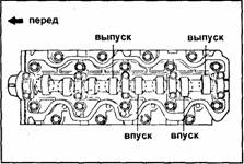
b) Adjust the valve clearances marked in the figure.
Measure the clearances of only those valves that are shown in the figure.
- Record measurement results that are out of specification. The measurement data will be required later when choosing the required shims (in my case, the size determined for each washer was “removed” at the factory).
Thermal clearances in valves
(measured on a cold engine):
intake valves. 0.20-0.30mm
exhaust valves. 0.25 - 0.35 mm
c) Rotate the crankshaft 360 ° and adjust the rest of the valves.
5. Adjustment of thermal clearances in the valves.
Note: the valves of one cylinder are controlled at the same time.
a) Turn the crankshaft so that the lug of the intake valve cam of the given cylinder is in a vertical position.
b) Rotate the notches on the pusher adjusting washers so that they can be accessed with a small screwdriver.
c) Depress the valve lifters.
d) Using a small screwdriver and magnetic bar, remove the shims.
e) Measure the thickness of the removed adjusting washer with a micrometer. Calculate the thickness of the new shim so that the design clearance meets the specifications given in the specification:
Select the shim that is closest to the design thickness. Note: Shims are available in 25 sizes, from 2.20 mm to 3.40 mm in 0.05 mm increments. The thickness is stamped on the washer.
e) Remove the special tool.
g) Recheck the valve clearance.
h) If necessary, adjust the clearances in the valves of other cylinders.
6. Install the cylinder head cover.
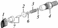
Component parts of the nozzle. 1- nozzle coupling nut; 2- spacer; 3- spring; 4- nozzle body; 5- adjusting washer; 6- pusher; 7- body and needle of the atomizer
2- drain pipe fastening nut;
4 - fuel return hose to the tank;
5-sealing washer of the injector nozzle;
6 - nozzle sealing washer;
7 - high pressure fuel lines.
1. Remove the high pressure fuel line clamps. Disconnect fuel lines from injectors and injection pump.
2. Unscrew the nuts securing the drainage pipeline and remove it together with the gaskets.
3. Remove the injectors (use a high tool head) and lay them out in the order of installation on the cylinders.
4. Remove the nozzle and sprayer seals from the head.
1 - fuel supply from injection pump
2 - channel for "return" of excess fuel
The nozzles are checked for general tightness, the tightness of the sprayer, the mobility of the sprayer needle, the pressure of the beginning of the opening of the sprayer needle, the shape of the atomized fuel jet and the presence of gas erosion of the sprayer and other performance indicators. Entrust the check to qualified specialists (here in Blagoveshchensk this is MIRAGE (a very large number of stands for testing engines, high pressure fuel pumps, injectors, etc.) and GRAND MOTORS).
Pressure of the beginning of the rise of the sprayer needle, bar
1. Replace the sprayer only with the one specified by the manufacturer.
2. Tighten the gun mount nut to 37 Nm.
Attention: applying a higher torque will deform the sprayer and damage it.
3. Thoroughly clean the nozzle slots in the block head. Install new sealing washers in the cylinder head socket. Install the injectors, tighten them to a torque of 64 Nm.
Attention: exceeding the tightening torque is not allowed.
4. Install new aluminum (the old system can suck in air) sealing washers of the drainage pipeline and the pipeline itself, tighten the fastening nuts to a torque of 29 N.m. Connect the drain line to the fuel return hose to the tank.
5. Install the high pressure fuel lines, starting from the one closest to the block, do not bend the fuel lines unnecessarily. Tighten the nuts securing the fuel lines to 29 Nm. Exceeding the tightening torque will result in fuel leaks.
6. Start the engine and check for fuel leaks.
7. Adjust idle speed (if necessary).
Adjust the gear shift in the automatic transmission with a throttle cable (commonly referred to as a KIK-down cable). Many owners of automatic transmissions on a minibus have such a defect. Over time, someone in the heat, someone after passing 80-90 km Automatic transmission, even sometimes with a smooth acceleration out of the blue, throws off OVERDRIVE-and on 3 speed... Sometimes this happens several times that tires the driver and begins to annoy and distract him, periodically forcing him to “play” the accelerator pedal.
Regulator on the high pressure fuel pump (TNVD)
1. Throttle cable going to the automatic transmission 2. fixing the shell with two nuts to the clamp to the high-pressure fuel pump
And the reason lies in a worn out or requiring adjustment of the throttle cable (it goes from the regulator of the injection pump to the automatic transmission), which gives information to the automatic transmission about the degree of pressing the pedal. Sometimes the cable “rubbing in” or falling out of the termination into a metal clamp (which leads to a decrease in its free travel) and no longer meets the requirements for automatic switching.
The principle of operation is such that when the throttle cable is fully extended, a downshift occurs (for example, from 4th to 3rd, from 3rd to 2nd, from 2nd to 1st). Since the throttle cam opens the oil valve when the cable is fully extended. If you fully extend it, you can go as on the first one - without switching.
We will tell you how to adjust it: Loosen the nuts for fixing the cable sheath (2) and fix it in such a way that the protruding end of the cable is not stretched (it sags a little and is completely pulled out of the sheath only at the position of the maximum regulator speed). We fix and check on the track in high-speed mode. If it is required to weaken even more, we select it experimentally. He performed similar actions on his car, achieved good results, switches back only during long ascents, as well as during intensive overtaking (with black smoke) ...
Supplement to the article sent to us
By changing the length of the throttle position cable, you actually control the oil reducer, which forms the pressure controlling the gearbox. It becomes a kick-down cable only when the gas pedal is fully depressed. By changing the length of the cable, you can set the gearbox operation modes: smoother - economy - by lengthening it, or sharper - sporty - by shortening. On new boxes there are similar switches, but on ours, you should choose the golden mean, otherwise the engine power is not used efficiently. When choosing a high gear, the diesel engine runs at low revs and accelerates very slowly - the diesel engine does not pick up. They keep the revs well, but accelerate slowly. Therefore, the entire set of speed is in low gears, an overdrive for a smooth ride! The problem under discussion is the shifting of the gear when the load increases. The pedal is not fully depressed - this is not a kick-down, therefore, this is a normal reaction of the box to the load. However, it may seem abnormal if there is any problem with the oil.
1.Low oil level - the pump traps air along with the oil and the resulting emulsion does not have the required compression properties, and the valve mechanism considers that there is a large overload and lowers the gear.
2. High level - the rims of the gears of the box cling to the oil and foaming it, the effect is the same.
3. Clogged oil filter - oil does not enter the pump - the pump is catching air - see above. An additional symptom is a sharp rise in the oil level on the dipstick. Those. start the car, measure the oil level and drive. When the effect of resetting the gears appears, they are measured again. Typically, the measured level is well above the heated oil level. The car stood at idle speed, the level is measured again and it drops to the normal level of heated oil!
Probably, there are also external faults. But they are all diagnosed as low pressure in the main oil line.
Our boxes, in principle, are considered indestructible, so you can try to rinse the filter and enjoy driving a new car.The only problem is the accuracy of the assembly. the oil tubes in the pan sit tight, but nowhere is it written. And once removed, it slips back into place - but doesn't hold the pressure! It is necessary to expand them by ten and install them tightly in place.
Overheating of the oil is also possible. When in July the temperature in Moscow exceeded +30, the car did not drive over 110 by any means. The oil cooler is clean outside, I don’t know inside - laziness. but as the temperature dropped to +25 everything is OK.
In the previous article, I provided information about weak spots and the disadvantages of the 1C diesel engine. The next generation of engines 2C from Toyota Motor Corporation, it would seem, on the contrary, should be of better quality, because the experience of the corporation and scientific and technological progress are constantly evolving. But unfortunately, nothing good can be said about diesel engines of the 2C line in comparison with 1C, but there are more drawbacks. Car Models Toyota in which these engines with a volume of 2L are installed are listed below:
- Kaldina CT190 / 196/198 from 1992 to 1998, 2C-I4, 2C-TI4;
- Karina CT150 from 1984 to 1988, 2C-T4;
- Karina CT170 / 176 from 1988 to 1992, 2C-I4;
- Karina CT190 / 195 from 1992 to 1996, 2C-I4;
- Karina 2 CT150 from 1983 to 1987, 2C-I4;
- Karina 2 CT170 from 1987 to 1992, 2C-I4;
- Karina E CT190 from 1992 to 1996, 2C-L-I4, 2C-II-I4;
- Crown CT150 1983 to 1987, 2C-II-I4, 2C-L-I4, 2C-I4, 2C-T-I4;
- Crown CT170 / 176/177 from 1987 to 1992, 2C-L-I4, 2C-I4, 2C-T-I4;
- Crown CT190 / 195 from 1992 to 1996, 2C-II-I4, 2C-L-I4,2C-T-I4;
- Litays / Town Ice CM26 from 1985 to 1986, 2C-I4, 2C-T-I4-T;
- Litays CM0 / 31/36/41 from 1985 to 1992, 2C-I4, 2C-T-I4-T;
- Litays / Town Ice CM51 / 52/55/60/61/65 from 1989 to 1999, 2C-I4, 2C-T-I4-T;
- Litays / Town Ice CP21 / 27/28/36 from 1984 to 1996, 2C-I4, 2C-T-I4-T;
- Litays / Town Ice CP41 / 51 from 1996 to 1989, 2C-I4, 2C-T-I4-T;
- Sprinter CE95 from 1989 to 1991, 2C;
- Sprinter CE100 / 104/106/108/109 from 1991 to 1998, 2C;
- Sprinter CE110 / 114 from 1995 to 1998, 2C;
- Avensis CT220 from 1997 to 2000, 2C-TE;
- Carolla CE110 from 1995 to 2001, 2C-E.
All the weak points and limitations engine 1C inherited 2C and additionally (see below).

- Loss of compression in two cylinders, in most cases in 3 and 4 cylinders;
- Rapid wear of 2C and 2C-T engines installed on minibuses;
- Lack of services for adjustment and the problem with parts for the injection pump with electronics in the event of its repair in 2C-E, 2C-TE engines.
Loss of compression in two cylinders, in most cases in 3 and 4 cylinders
Loss of compression, as a rule, in problematic 3 and 4 cylinders of engines occurs due to leaks in the air pipes connecting the air filter with the turbine and with the air manifold. Dust penetrates through leaky places and mixes with oil and comes with oil to the surface of rubbing parts, grinds them down and quickly renders them unusable. For this reason, the cylinder-piston group and the intake valve plates quickly fail. Accordingly, the wear of the valve discs increases the thermal clearances, and the compression disappears.
Rapid wear of 2C and 2C-T engines installed on minibuses
To put it simply, these motors are not designed for vans, because they are much heavier and larger in size, which increases the load on the engines. On engines with electronically controlled injection pumps, this problem is absent.
Lack of services for adjustment and the problem with parts for the injection pump with electronics in the event of its repair in 2C-E, 2C-TE engines
Of course, the electronically controlled injection pump has benefited the engines:
- reduced fuel consumption;
- reduction of toxic emissions;
- increased uniformity of engine operation;
- motors are quiet.
But the disadvantage is that very rarely there are services that are capable of diagnosing, adjusting such high-pressure fuel pumps in accordance with the modes and parameters set by the designers. The difficulty is that there are no specialists of this level of training, as well as spare parts and technological equipment for the required work.
P.S. Dear Toyota owners with 2C engines! You can comment on the weaknesses and shortcomings identified by you in your personal practice when operating cars.
To tell the truth, motors 2C and 2C-T can deservedly be called a word starting with the letter G. Quality is no one disorder ... The problem, as I understood not only for me, but for all diesel operators, is the outlet of gases to the radiator and expansion tank.The reason is hidden in weak partitions on the motor head, as a result of a slight overheating of the engine, microcracks appear, which are very difficult to find, as a result, the engine is repaired. And it's better not to come up with repairs and put 3C and forget about all the problems - this is a already passed stage.
I disagree. When overheated, microcracks will appear in any engine. It is necessary to monitor the cooling system. If all systems are in good working order, the engine looks like a long time. For example, I have Kaldin for 2C, 400 thousand km without major repairs, I decided to measure the compression in the cylinders, everywhere at 32-33, so you can forget about the capital for now.
Any engine can be ruined. You need to monitor him carefully and he will not let you down. Great engine.
Can you please tell me if the 2c engine will fit the Lit Ice mini truck?
What is the engine model? 2CT or just 2C? (with or without turbine this is important for diagnostics)
Describe in detail the problem, under what conditions does it smoke, what color of the smoke, is there a smell of burnt oil on the exhaust?
Good day, guys, the gasket under the boss burned out for 2s. the starter does not start the rope again, the motor, warmed up to the working one, starts from 10 meters (I diagnosed and repaired the nozzle head) tell me what to do I have been suffering for 3 weeks
It drives not through the nozzles, but through the breather of the intake manifold, most likely
Cars change, friends and the forum remain. [my.housecope.com/wp-content/uploads/ext/1209]
Message eNkee "01 Oct 2012, 13:47
In general, my engine is dying (2C), piston rings are caput, they need to be changed. I wanted to buy a contract drive for less than 75000r, I did not find it, I decided to do it myself.
In general, I want to change the piston rings, tell me who knows how much it will cost me a pretty penny, rings, gaskets, everything, grinding the cylinder head, of course, and what else is needed to make the capital with your own hands!
In general, what do I need to buy for all this and how much is the price of all this.
Message brembist »01 Oct 2012, 13:58
Message eNkee »01 Oct 2012, 14:55
Message brembist »01 Oct 2012, 15:00
Message Alexandr "01 Oct 2012, 16:40
Message eNkee »02 Oct 2012, 07:02
Message Speedyman »02 Oct 2012, 08:05
Message brembist »02 Oct 2012, 08:46
Message Andy73 02 Oct 2012, 10:54
eNkee, here's the topic: Calculation of overhaul
do not try to "throw rings"! 
brembist, +1, 2C a lot in the country.
In the mid-2000s, Toyota engineers completed the development of a new diesel engine, as a result, the production of Toyota 1AD-FTV and 2AD-FTV engines was launched on the automaker's conveyor belt. These power units, with a displacement of 2 and 2.2 liters, respectively, become the most massive Toyota diesel engine of the late 2000s for Toyota RAV4 and Toyota Corolla Verso, Avensis cars. In our review, we will look at the features of a rarer, compared to the two-liter version, the 2 AD-FTV engine (2.2 liters).
The 2AD-FTV engine is a four-cylinder in-line power unit with 4 valves per cylinder (with hydraulic compensators), a timing chain drive, an oil-cooled VGT (Variable Guide Vane Geometry) turbine and a Common Rail (DENSO) power system. A distinctive feature of the 2.2 liter Toyota diesel engine is the presence of a balancing mechanism driven by the crankshaft gears. The engine was based on a new for that time, and now used by most automakers, "disposable design" - an alloy cylinder block with cast iron liners, which does not provide for overhaul. Nevertheless, these motors are considered quite reliable and allow the car to roll out up to 400-450 thousand kilometers.
Denso injectors, which are equipped with 2AD-FTV diesel engines, have established themselves as a very reliable element of the fuel system. They do not cause problems up to 200-250 thousand kilometers, and after that, in most cases, they easily undergo restoration and preventive maintenance and continue to work properly. True, the nozzles of this company cost a lot - one new nozzle will cost you about 20,000 rubles.After the engine was modified in 2009 (the new engine was marked 2AD-FHV), piezoelectric injectors were used in the fuel system, which are no longer amenable to restoration.
The most common malfunction of Toyota 2.2 liter 2AD-FTV diesel engines manufactured before 2009 is the erosion of the engine block at the junction with the cylinder head as a result of the interaction of metal and coolant. As a result, on many engines, the liquid from the cooling system begins to get into the oil, as a result, an expensive overhaul. Although the 2AD-FTV engine was installed on several Toyota models, block erosion problems were most often encountered on the 2nd generation Toyota Avensis; some of the cars were recalled by the manufacturer for preventive maintenance - block grinding and gasket replacement. The presence or absence of such a problem also directly depends on the operating conditions of the engine.
Structurally, the 2AD-FTV engines are referred to as "greedy" in terms of oil power units, i.e. suggest a fairly high oil consumption, and this, in turn, entails a number of potentially possible and regularly occurring troubles associated with the widespread formation of carbon deposits. Because of this, the resource of the EGR valve is reduced, it requires regular cleaning. When using low-quality oil, carbon deposits quickly form on the pistons, which increases the risk of serious damage to the mechanical part of the power unit.
Also, typical difficulties arising during the operation of a Toyota 2.2 2 AD-FTV diesel engine include:
- leaking cylinder head gaskets;
- pump leak;
- oil leak from under the pan gasket.
In general, the 2AD-FTV engine cannot be attributed to the “millionaire”, but this power unit fulfills the normal resource for a diesel engine. In our online store you can purchase a 2008 Toyota 2.2 2AD-FTV contract engine from Spain with a confirmed original mileage of 92 thousand km. Engine condition is excellent, the donor car has been damaged by fire from the trunk side - the engine compartment and engine are not affected.
You know what fuel in Russia, you need to clean the nets in the fuel pump, and how many of them and where and how to get don’t, I don’t know.
and one more trouble - the engine is running low speed 650
warms up more than 850
on the tolmouth I read it should be the other way around, initially large, and with warming up, some kind of engine warming up device will decrease there
is it possible to customize it at home - if it is not difficult to explain what and how in detail.
if there are photos, it will be clear and clear what and where, but it's so scary to climb
well, about the rest of the sores next time
and so I do not regret that I bought a diesel-it is trouble-free, reliable, strong = it's absolutely super 
catching up with the number
1 what this bolt regulates
2 bolt on it, the spring is
3 what kind of electronic unit 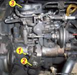
the car is not started - normally it does not drip
as soon as you start it, it starts to drip on a cold one
it will warm up for 5-10 minutes all the way does not drip it is not scary
and how to fight with it or inappropriately
how to check the speed increase valve when the stove is turned on
I turn on the stove does not add
I found him, but I don’t know what to do
Added by (10 Feb 2010, 08:09)
———————————————
I am writing a full report on the work done with your help
started the engine, adjusted the speed with the bolt
engine is warming up rpm does not drop
began to study the structure of what and how interacts
the heating valve comes out with increasing temperature
but the turnover does not fall, it turned out that
by the way, drops of antifreeze drip from it a little 15 - 20
it turned out that
Vacuum actuator for increasing the speed of XX in connection with the inclusion of the refrigerator, air conditioner or button for increasing the speed of XX.
is involved in this system and with its hook does not allow the bar to move away
increased the stroke on it until it began to interfere with work
the heating valve and everything with the hoist as it should work
tell me what rpm should be on the engine
1 heated
2 cold
I have automatic transmission
it seems there are differences with the mechanics
about the nets, you wrote that the Japanese are all the same fuel injection pump
but this is the first time I see the fuel pump and I don't know where other nets are
but I'm afraid to climb in the wrong place if you can show it in the photo
I changed the fuel filter to a fuel pump and blow it out and it would be good
thanks again without you I would be lost
on other forums was engaged in verbiage of no sense
but here everything is clear at once you can see the specialist
if what manuals on machines in electronic form are needed, write off what I scanned from what I dug on the Internet
I opened the flushing liquid right here
and in stores they sell pouring directly into fuel
as if it washes the pump. injectors. the valves say
that after it the engine works better, it should be applied every 5000t km
do not you know you can use this?
The first step is to clarify that in the case of the Toyota engine, designated D-4D, we are talking about two radically different power units. The oldest of them was produced until 2008, had a volume of 2 liters and developed a power of 116 hp. It consisted of a cast iron block, a simple 8-valve aluminum head and had a belt-type timing drive. These motors were identified by the CD code. The owners of cars with such engines rarely complained of serious malfunctions. All claims concerned only the injectors (easy to restore) and components typical of modern diesel engines - the EGR valve and the turbocharger. In 2008, the CD turbodiesel disappeared from Toyota's range.
In 2006, the Japanese introduced a new family of diesel engines with a displacement of 2.0 and 2.2 liters, which were also designated D-4D. Among the differences: an aluminum block and a 16-valve head, and instead of a belt, a durable timing chain drive. The new product received the AD index.
First impressions were only positive - higher output and lower fuel consumption. But it soon became clear that the new engine had several weak points. The most important and terrible is the oxidation of aluminum in contact with the head gasket, which occurs after about 150-200 thousand km. The defect is so serious that it will not be possible to get rid of it by simply replacing the gasket. Grinding of the surface of the head and block is required. To grind the cylinder block, the engine must be removed from the vehicle. This kind of repair can only be done once. Re-troubleshooting will cause the head to drop so much that the pistons will hit the valves when trying to start the engine. Thus, a second repair is impossible and economically unreasonable. Will save only the replacement of the block or "de facto" - the installation of a new engine.
Toyota, at least in theory, dealt with the problem in late 2009. On serviced cars, if this malfunction was detected after modernization, the manufacturer changed the engine at its own expense. However, the problem with the gasket under the block head still exists. Most often, the defect pops up in heavily operated Toyota with the strongest 2.2-liter version of the engine.
Before buying a car equipped with a diesel D-4D AD series, be sure to ask the owner about previously performed repairs, and ask, if possible, to show invoices for payment of repairs or certificates of work performed. There are a lot of cars on the market with a diesel engine that has already gone through the first repair. Remember, a second repair is not possible, only an engine replacement!
| Video (click to play). |
Application: Avensis II, Auris, RAV4 III, Corolla E15, Lexus IS 220d.


