In detail: a generator for repairing radio equipment with your own hands from a real master for the site my.housecope.com.
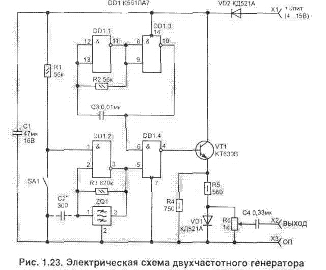
When repairing a sound amplifier or household radio at home, it is often necessary to trace the passage of a signal through the stages. The one shown in fig. 1.23 diagram of a simple two-frequency generator. It is assembled on only one CMOS microcircuit and does not contain any winding units. What makes the device easy to manufacture, configure and operate.
This generator makes it possible to check not only the audio amplifier, but also the path of the intermediate frequency amplifier (IFA) of the radio receiver. The generator also allows you to adjust the IF loops of the radio receiver to the maximum signal level.
At the output (X2) of the device there will be radio pulses with a frequency of 465 kHz, modulated by a low-frequency signal - 1 kHz (100%
modulation). In this case, if you turn on SA1, then only a low-frequency signal will appear at the output - pulses with a frequency of 1 kHz.
The high-frequency generator operates at a frequency of 465 kHz and to obtain high stability for it, it is made using a piezoceramic filter (ZQ1) of the FP1P-022 type in the negative feedback circuit of the element of the DD1.2 microcircuit. Such filters are more readily available and cheaper than quartz resonators for the corresponding frequency.
The pulse generator of the sound range (DD1.1-DD1.3) is assembled according to the classical scheme and does not need any explanations. On element DD1.4, two frequencies are mixed and fed to the emitter follower, made on the transistor VT1. The transistor matches the high output impedance of the microcircuit with a possible low resistance in the load circuit.
| Video (click to play). |
The generator provides operation in a wide range of supply voltages (4 ... 15 V) and consumes a current of 3.7 ... 26 mA. In this case, the frequency of the high-frequency auto-generator changes over the entire range of supply voltages by no more than 400 Hz, which is quite acceptable.
In order for the level of the output signal of the oscillator to be highly independent of the supply voltage of the circuit, there is a limiting diode VD1 at the output. The output signal after the capacitor C4 will have a maximum amplitude of about 0.3 V, and using the resistor R6 it can be reduced to the required value.
Diode VD2 prevents erroneous supply of polarity of the supply voltage to the circuit.
In the circuit, you can use a piezofilter (ZQ1) of the FP1P-022 ... 027 type. The regulating resistor R6 is of the SP0-0.5 type, and the rest of the resistors are МЯТ and С2-23. Capacitors: C1 - K53-1 at 16_V; C2 ... C4 - K10-17.
The circuit is simple enough that it can be easily mounted on a universal breadboard.
The setting consists in setting the selection of the resistor R2 (with closed contacts SA1) at a frequency of 1 kHz at the output. After that, using a frequency meter, we check the frequency of 465 kHz ± 0.5 kHz.
In order to make it convenient to measure the frequency, we turn off the modulation of the RF signal, which can be done by applying the supply voltage to the terminals DD1 / 12, 13.
If, due to the scatter of the parameters of the logic elements (internal capacitance of the microcircuit), the piezofilter ZQ1 does not work exactly at a frequency of 465 kHz, then it may be necessary to install an additional capacitor C2 with a capacity of about 100 ... small limits.
Literature:
I.P. Shelestov - Useful schemes for radio amateurs, book 3.
Our additional services and sites:
project support:
place our button on your page! And we will place your button or link on our page.
Practical advice for radio mechanics, radio installer and radio amateurs
Simple generators-probes, probes-generators and other devices for detecting faults in radio equipment
In the repair and amateur practice, the following devices can be used to quickly check the health of high-frequency, low-frequency radio circuits and to detect malfunctions in televisions, radios and other equipment.
1. The generator-probe on one transistor (Fig. 69.6) is designed for quick testing of stages of amplifiers or radio receivers.
The schematic diagram of the probe generator is shown in Fig. 69, a. It generates a pulse voltage with an amplitude sufficient to test the front-end and front-end amplification stages of low-frequency structures. In addition to the fundamental frequency, the output of the probe will have a large number of harmonics, which makes it possible to use it for testing high-frequency stages - intermediate and high frequency amplifiers, local oscillators, converters.
Oscillation occurs due to strong positive feedback between the collector and base circuits of the transistor. The signal taken from the base winding of the transformer Tpl is fed through the capacitor C / to the potentiometer R1, which regulates the output voltage of the probe.
The transformer is wound on a small piece of ferrite core. Winding I contains 2000 turns of PEL 0.07 wire, and winding II contains 400 turns of PEL 0.1 wire.
Transistor type MP39-MP42. The power supply battery is an element “332” with a voltage of 1.5 V or a small-sized accumulator of the D-0.1 type.
The probe is assembled in a small case (Fig. 60.6). To connect to the chassis or a common wire of the tested design, a flexible mounting wire with a crocodile clip at the end is brought out. A medical needle from a Record syringe is used as a metal probe. At the end of the case, a potentiometer is installed, on the knob of which there is a risk, which makes it possible to judge the output signal.
Rice. 69. Generator probe on one transistor
2. The generator-probe on two transistors without a transformer (Fig. 70) produces rectangular pulses and allows you to check all stages of the amplifier or radio receiver. Moreover, the oscillation frequency can be changed by the capacitance of the capacitor C1: with an increase in the capacitance, the frequency decreases. And changing the resistance of the resistors affects the shape of the output oscillations: with an increase in R2 and a decrease in R3, it is easy to achieve sinusoidal oscillations at the output and thus turn the probe into a sound generator with a fixed frequency.
The transistors, battery, and design are the same as in the single transistor probe generator.
3. An amateur radio probe generator is designed to check the health of high-frequency and low-frequency radio circuits of household equipment (radio receivers, televisions, tape recorders). The schematic diagram of the probe is shown in Fig. 7 !. It is a multivibrator assembled on transistors 77, T2. The received signal is rectangular, the oscillation frequency is about 1000 Hz, the pulse amplitude is not less than 0.5 V. The probe-generator is assembled in a plastic case, the length of the probe together with the needle is 166 mm, the diameter of the body is 18 mm.
Power supply from one element "316" with voltage of 1.5 V.
To turn on the probe generator, press the button and touch the tested cascade of the device with the tip of the probe. It is recommended to check the cascades sequentially, starting from the input device.
If the tested cascade is in good working order, a characteristic sound (speaker, telephone) or a strip (kinescope) will be heard at the output.
When checking devices that do not have a speaker or a kinescope at the output, high-impedance headphones of the TON-2 type can serve as an indicator. It is strictly forbidden to test circuits with voltages higher than 250 V.
When checking the circuits, do not touch the body of the tested device with your hands.
This probe generator is manufactured by our industry.
Rice. 70. Generator probe on two transistors
4.A small-sized device for detecting malfunctions in televisions, radios and other household radio equipment by listening to sound in the speaker of the device under test, observing the image on the TV screen or connecting another indicator to the output of the device under test (voltmeter, headphones, oscilloscope, etc.).
The device allows you to check on TVs: through channel, image channel, sound channel, synchronization circuits, frame linearity; in radio receivers: end-to-end path, channel of the IF amplifier, detector and ULF.
The device is a complex waveform generator. The low-frequency component of the signal has a repetition rate of 200-850 Hz. The high-frequency component has a frequency of 5-7 MHz. The specified signal allows you to receive 2-20 horizontal stripes on the TV screen and sound in the speaker.
The signal voltage at the output of the device is regulated by a potentiometer.
The device is powered by the Krona-VTs battery. The consumed current is not more than 3 mA.
Overall dimensions of the device without flexible outlet no more than 245 X X 35 X 28 mm. The length of the flexible lead is at least 500 mm. The mass of the device is not more than 150 g.
The electrical diagram of the device is shown in Fig. 72, a. The generator with intermittent excitation is made on the transistor 77 according to the scheme with a common base.
Intermittent excitation of the generator ensures the presence of chains R3, C4 in the emitter circuit. The signal at the emitter of the transistor 77 is the sum of the intermittent high-frequency voltage and the charge and discharge voltage of the capacitor C4.
Rice. 71. Probe generator radio amateur
Rice. 72. Small-sized device for detecting malfunctions in televisions
On the transistor 72 there is an emitter q-follower, which serves to increase the stability of the generator and reduce the input resistance of the device. Adjustment of the output signal level is carried out using the L ”5 potentiometer.
The body of the device is made in the form of two split covers made of impact-resistant polystyrene (Fig. 72.6).
The covers are connected using a screw and a ferrule, which is also used to connect the instrument to the device under test. The housing contains the device board and the "Krona-VTs" battery. The device is connected to the chassis of the device under test with a crocodile clip.
To determine the malfunction of the amplifying paths, the circuit is checked cascadingly, starting from the end of the tested path. To do this, a signal is sent to the input of the cascade by touching the tip of the device, while the absence of a signal on the indicator (TV screen, speaker, voltmeter, oscilloscope, headphones, etc.) will indicate a cascade malfunction.
To determine the nonlinearity of the image along the vertical it is necessary: to obtain an image of the horizontal stripes; measure the minimum and maximum distance between two adjacent lanes; determine the vertical nonlinearity.
The stability of the image synchronization is judged by the stability of the horizontal stripes on the TV screen.
It should be borne in mind that the device is designed to be connected to points of electrical circuits, the voltage of which does not exceed 250 V relative to the case. Voltage refers to the sum of DC and impulse voltages acting in the circuit.
A small-sized device for detecting malfunctions in TVs is produced by our industry.
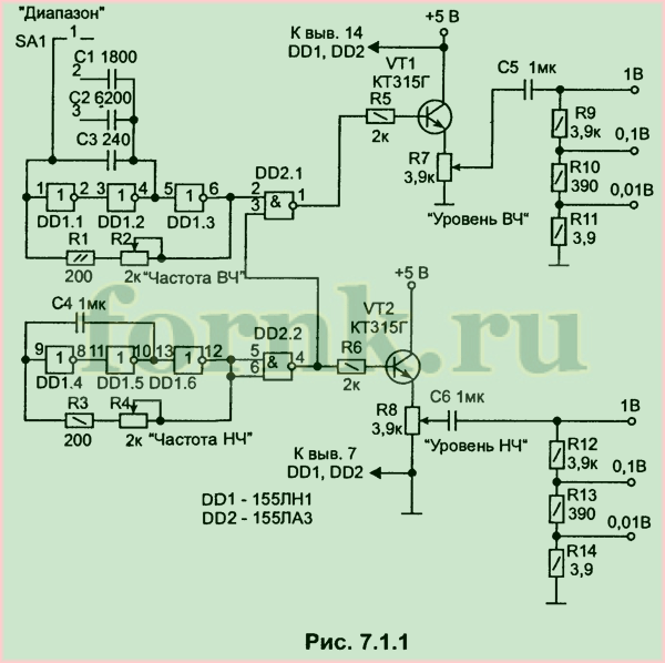
This the simplest generator serves to adjust the input electrical circuits of radio receivers with a range of DV, MW and HF, and to adjust the ULF. The electrical circuit of the generator is shown in Fig. 7.1.1.
It has 2 independent adjustable low-frequency and high-frequency generators built on TTL microcircuits. Each of the generators has its own output, which has a voltage divider. The electrical signal from the high-frequency generator at the output is modulated with low-frequency signals from pin 4 of the DD2 microcircuit.
It is possible to use in the device without changing the parameters radioelements of the following series: 555, 531, 530, 533. Capacities C1-C4 of the KLS, KD, KM type.The brands of other radioelements can be any. The operating frequency range of the HF generator is divided into 3 sub-ranges: 110 ... 510 kHz; 420 ... 1700 kiloHertz and 2.4 ... 10 5 megaHertz (choice - SA1).
The LF generator operates in the frequency range 400 ... 1600 Hz. When repeating this circuit, the knobs of the variable resistances R2, R4, R7, R8 and the range switch are located on the front panel of the generator. The elements of the generator are powered from an arbitrary stabilized power supply unit for 5 volts, and withstanding a load current of up to 100 ... 200 mA.
"Designs and technologies to help electronics lovers", Elagin N.A.
Someone is lucky and he has a workshop equipped with measuring instruments
And this one is for those who do not have instruments, but have a desire to learn how to tune radios, amplifiers and other equipment.
the other day I was disappointed, the generator, bought for various experiments, quite by accident turned out to be a rarity
viewtopic.php? f = 2 & t = 2579 & start = 20
And now I don't know what to do with it, modify it or leave it as a monument
But nothing appeared such a simple oscilloscope
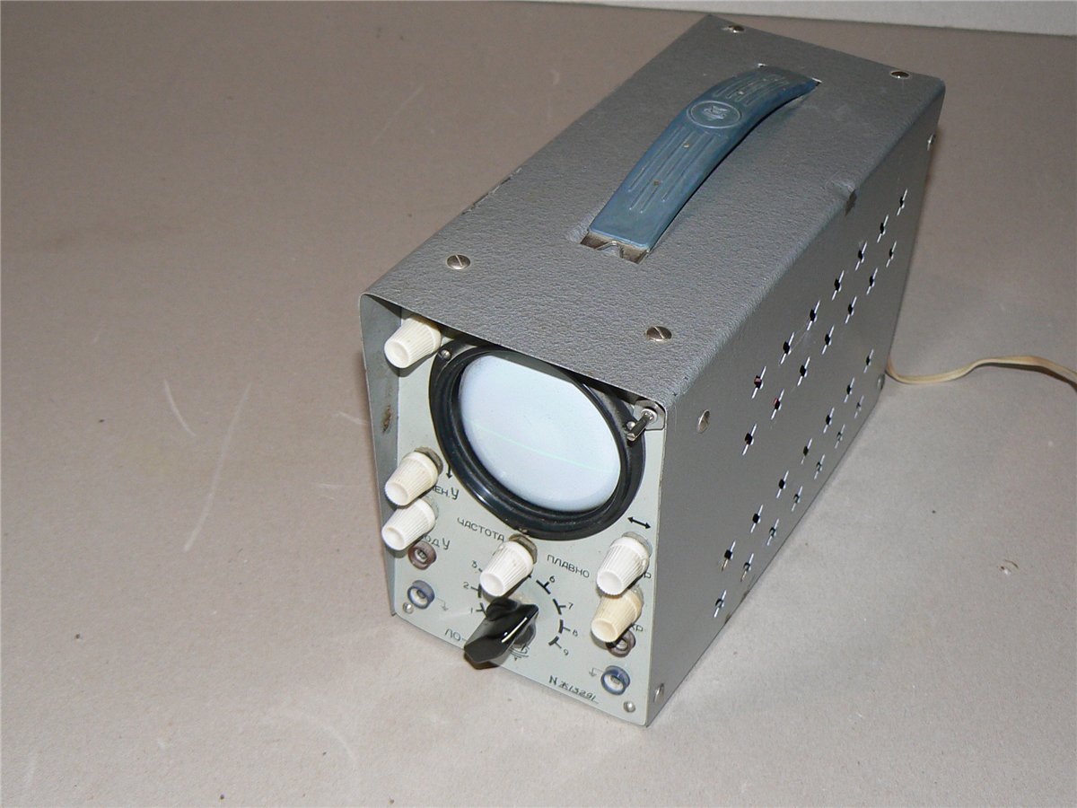
Naturally, I immediately wanted to check it out.
The beginning was encouraging - good brightness, synchronization, and this is at a frequency of 142 kHz
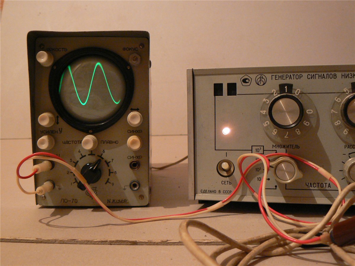
True, after 15 minutes of warming up, the image almost completely went sideways and does not want to return in any way. But these are trifles. The main thing is a good pipe and there is general performance.
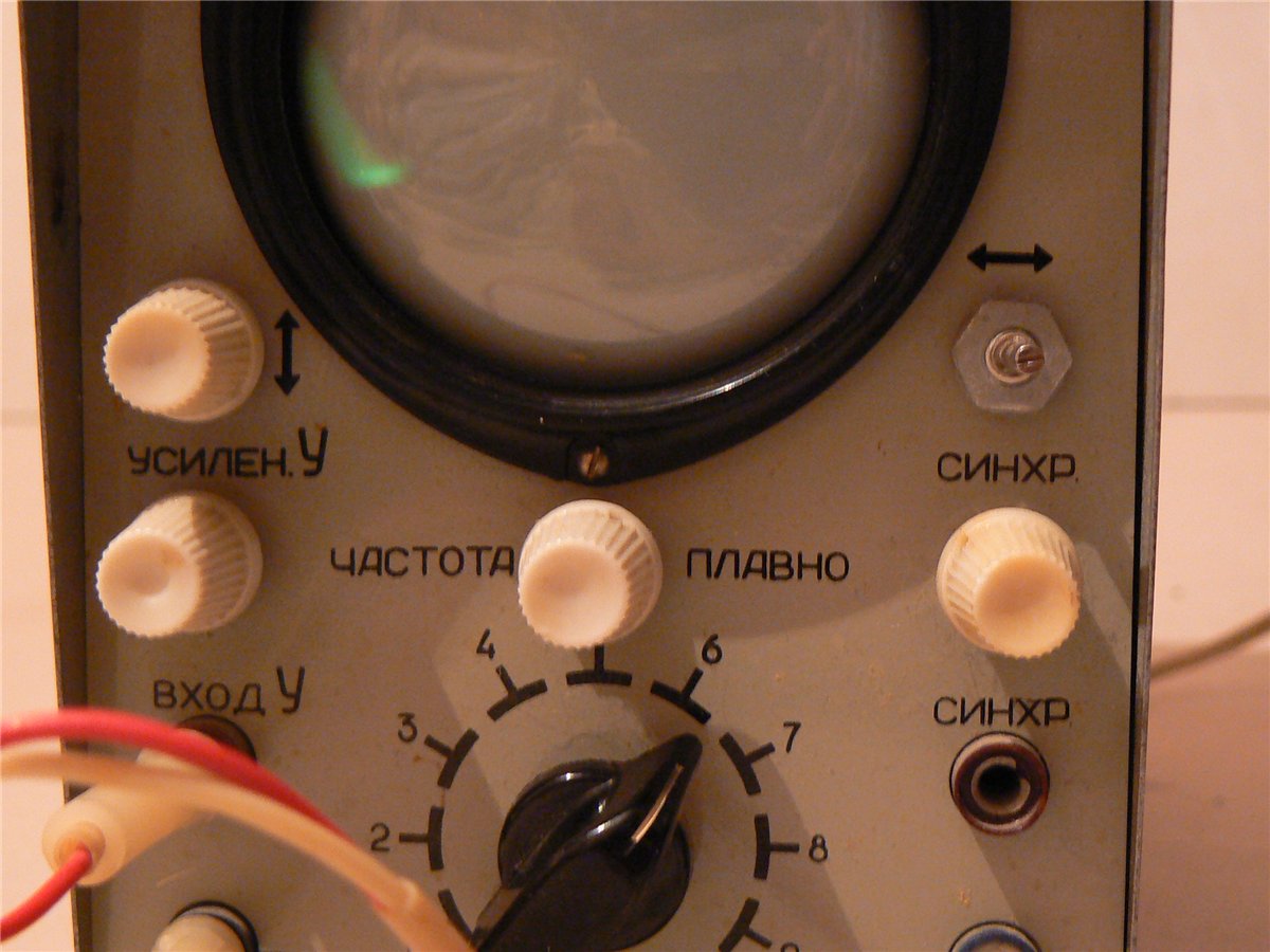
But this oscilloscope will be needed a little later.
The first, in priority, needs a generator to test the IF of radio receivers.
_________________
Manyuk writes: “. And I don’t paint receivers, I don’t know how. I can only put the loot in my pocket. "
When repairing a sound amplifier or household radio at home, it is often necessary to trace the passage of a signal through the stages. The one shown in fig. 1.23 diagram of a simple two-frequency generator. It is assembled on only one CMOS microcircuit and does not contain any winding units. What makes the device easy to manufacture, configure and operate.
This generator makes it possible to check not only the audio amplifier, but also the path of the intermediate frequency amplifier (IFA) of the radio receiver. The generator also allows you to adjust the IF loops of the radio receiver to the maximum signal level.
At the output (X2) of the device there will be radio pulses with a frequency of 465 kHz, modulated with a low-frequency signal - 1 kHz (100% modulation). In this case, if you turn on SA1, then only a low-frequency signal will appear at the output - pulses with a frequency of 1 kHz.
The high-frequency generator operates at a frequency of 465 kHz and to obtain high stability for it, it is made using a piezoceramic filter (ZQ1) of the FP1P-022 type in the negative feedback circuit of the element of the DD1.2 microcircuit. Such filters are more readily available and cheaper than quartz resonators for the corresponding frequency.
The pulse generator of the sound range (DD1.1-DD1.3) is assembled according to the classical scheme and does not need any explanations. On element DD1.4, two frequencies are mixed and fed to the emitter follower, made on the transistor VT1. The transistor matches the high output impedance of the microcircuit with a possible low resistance in the load circuit.
The generator provides operation in a wide range of supply voltages (4.15 V) and consumes 3.7 current. 26 mA. In this case, the frequency of the high-frequency auto-generator changes over the entire range of supply voltages by no more than 400 Hz, which is quite acceptable.
In order for the level of the output signal of the oscillator to be highly independent of the supply voltage of the circuit, there is a limiting diode VD1 at the output. The output signal after the capacitor C4 will have a maximum amplitude of about 0.3 V, and using the resistor R6 it can be reduced to the required value.
Diode VD2 prevents erroneous supply of polarity of the supply voltage to the circuit.
In the circuit, you can use a piezofilter (ZQ1) of the FP1P-022 type. 027. Regulating resistor R6 of the SPO-0.5 type, and the remaining resistors MLT and C2-23.Capacitors: C1 - K53-1 16 V; C2. C4-K10-17.
The circuit is simple enough that it can be easily mounted on a universal breadboard.
The setting consists in setting the selection of the resistor R2 (with closed contacts SA1) at a frequency of 1 kHz at the output. After that, using a frequency meter, we check the frequency of 465 kHz ± 0.5 kHz.
In order to make it convenient to measure the frequency, we turn off the modulation of the RF signal, which can be done by applying the supply voltage to the terminals DD1 / 12, 13.
If, due to the spread of the parameters of the logic elements (internal capacitance of the microcircuit), the piezofilter ZQ1 does not work exactly at a frequency of 465 kHz, then it may be necessary to install an additional capacitor C2 with a capacity of about 100.470 pF, as well as the selection of a resistor R3, which will allow to shift the operating frequency of the generator to small limits.
You can purchase a set of parts to build this generator probe here /forum/viewtopic.php?f=23&t=88
You can discuss the design, express your opinion and suggestions at forum
S. Belenetsky, US5MSQ Kiev, Ukraine
Tell me if it is possible to replace FP1PF-61 with a bourgeois ceramic resonator CRB465E
Hello.
I gave you an answer on the forum (the link to it is indicated at the end of the article)
It is also better to discuss circuit solutions and ask questions there.
And here is a place only for reviews and comments
You must be logged in to post a comment.
In repair and amateur practice, the following devices can be used to quickly check the health of high-frequency, low-frequency radio circuits and to detect malfunctions in televisions, radio receivers and other equipment.
A single transistor probe generator is designed for quick testing of amplifier or radio cascades. The schematic diagram of the probe generator is shown in Fig. 1. It generates a pulse voltage with an amplitude sufficient to test the pre-terminal and input amplification stages of low-frequency structures.
Rice. 1. Generator probe on one transistor.
In addition to the fundamental frequency, the probe output will have a large number of harmonics, which makes it possible to use it for testing high-frequency stages - intermediate and high frequency amplifiers, local oscillators, converters.
Oscillation occurs due to strong positive feedback between the collector and base circuits of the transistor. The signal taken from the base winding of the transformer Tr1 is fed through the capacitor C1 to the potentiometer R1, which regulates the output voltage of the probe.
The transformer is wound on a small piece of ferrite core. Winding I contains 2000 turns of PEL 0.07 wire, and winding II contains 400 turns of PEL 0.1 wire.
Transistor type MP39 - MP42. Power supply battery - element "332" with voltage of 1.5 V or small-sized battery.
The probe is assembled in a small case (Fig. 1b). To connect to the chassis or a common wire of the tested design, a flexible installation wire with a crocodile clip at the end is brought out.
A medical needle from a Record syringe is used as a metal probe. At the end of the case, a potentiometer is installed, on the knob of which there is a risk, which makes it possible to judge the output signal.
The generator-probe on two transistors without a transformer produces square-wave pulses and allows you to check all stages of an amplifier or radio receiver.
Rice. 2. Generator probe on two transistors.
Moreover, the oscillation frequency can be changed by the capacitance of the capacitor C1: with an increase in the capacitance, the frequency decreases. And changing the resistance of the resistors affects the shape of the output oscillations: with an increase in R2 and a decrease in R3, it is easy to achieve sinusoidal oscillations at the output and thus turn the probe into a sound generator with a fixed frequency. The transistors, battery, and design are the same as in the single transistor probe generator.
The amateur radio probe generator is designed to test the health of high-frequency and low-frequency radio circuits of household equipment (radio receivers, televisions, tape recorders). The schematic diagram of the probe is shown in Fig. 3.
It is a multivibrator assembled on transistors T1, T2. The received signal is rectangular, the oscillation frequency is about 1000 Hz, the pulse amplitude is not less than 0.5 V. The probe-generator is assembled in a plastic case, the length of the probe together with the needle is 166 mm, the diameter of the case is 18 mm.
Power supply from one element "316" with voltage of 1.5 V. To turn on the probe-generator, press the button and touch the tested cascade of the device with the tip of the probe. It is recommended to check the cascades sequentially, starting from the input device.
Rice. 3. Probe generator radio amateur.
If the tested cascade is in good working order, a characteristic sound (speaker, telephone) or a strip (kinescope) will be heard at the output.
When checking devices that do not have a speaker or a kinescope at the output, high-impedance headphones of the TON-2 type can serve as an indicator. It is strictly forbidden to test circuits with a voltage higher than 250 V. When checking circuits, do not touch the body of the tested device with your hands.
A small-sized device for detecting malfunctions in televisions, radios and other household radio equipment by listening to the sound in the speaker of the device under test, observing the image on the TV screen or connecting another indicator (voltmeter, headphones, oscilloscope, etc.) to the output of the device under test.
The device allows you to check on TVs: through channel, image channel, sound channel, synchronization circuits, frame linearity; in radio receivers: end-to-end path, channel of the IF amplifier, detector and ULF.
The device is a complex waveform generator. The low-frequency component of the signal has a repetition rate of 200-850 Hz. The high-frequency component has a frequency of 5-7 MHz. This signal allows you to get 2-20 horizontal stripes on the TV screen and sound in the speaker.
Rice. 4. Small-sized device for detecting malfunctions in TVs.
The signal voltage at the output of the device is regulated by a potentiometer. The device is powered by the Krona-VTs battery. The consumed current is not more than 3 mA.
Overall dimensions of the device without flexible outlet no more than 245 X X 35 X 28 mm. The length of the flexible lead is at least 500 mm. The mass of the device is not more than 150 g.
The electrical diagram of the device is shown in Fig. 4, a. The generator with intermittent excitation is made on the T1 transistor according to the scheme with a common base.
Intermittent excitation of the generator ensures the presence of chains R3, C4 in the emitter circuit. The signal at the emitter of the transistor 77 is the sum of the intermittent high-frequency voltage and the charge and discharge voltage of the capacitor C4.
An emitter follower is made on the transistor T2, which serves to increase the stability of the generator and reduce the input resistance of the device. The output signal level is adjusted using potentiometer R5.
The body of the device is made in the form of two split covers made of impact-resistant polystyrene (Fig. 4, 6). The covers are connected using a screw and a ferrule, which is also used to connect the instrument to the device under test. The housing contains the device board and the "Krona-VTs" battery. The device is connected to the chassis of the device under test with a crocodile clip.
To determine the malfunction of the amplifying paths, the circuit is checked cascadingly, starting from the end of the tested path. To do this, a signal is sent to the input of the cascade by touching the tip of the device, while the absence of a signal on the indicator (TV screen, speaker, voltmeter, oscilloscope, headphones, etc.) will indicate a cascade malfunction.
To determine the nonlinearity of the image along the vertical it is necessary: to obtain an image of the horizontal stripes; measure the minimum and maximum distance between two adjacent lanes; determine the vertical nonlinearity by the formula:
where H is nonlinearity,%; Imax - maximum distance between stripes; Imnnnm - minimum distance between stripes. The stability of the image synchronization is judged by the stability of the horizontal stripes on the TV screen.
It should be borne in mind that the device is designed to be connected to points of electrical circuits, the voltage of which does not exceed 250 V relative to the case. Voltage refers to the sum of DC and impulse voltages acting in the circuit.
I propose a generator circuit for tuning the receiving and transmitting paths of transceivers and other high-frequency radio equipment.
The generator consists of three main parts: an autogenerator of high-frequency oscillations on a transistor VT1; RF amplifier, made on transistors VT2 and VT3, and a modulator on VT4.
The RF generator is assembled according to the inductive three-point scheme. It has four HF sub-bands from 2 to 30 MHz and two - U KB from 50 to 160 MHz. Loop coils L1. L6 are wound on frames 08 mm. The first four coils have ferrite cores, the other two are coreless. Taps are made from 1/3 of the total number of turns, counting from the top according to the output circuit. Coil data are given in the table. Capacitor C3 is equipped with a large scale, graduated in megahertz, and C4 - with a small scale with marks from 0 to 10. It is more convenient, of course, to include a digital frequency meter at the generator output for control.
Generator parameters
Generated frequency range, MHz 2.160
Number of sub-bands 6
Output voltage, V, not less than 1
With a step attenuator, you can change the value of the output voltage (1 V, 100, 10, 1 mV). The modulator is an RC oscillator. Its oscillation frequency is about 1000 Hz. If necessary, using the SB2 switch, it can be turned off.
The radio receiving paths of various equipment (radio receivers, radio tape recorders, CBC transceivers, etc.) contain such units of the same type as audio frequency amplifiers (3CH), intermediate frequency amplifiers (IF) of FM and AM stations. They have to be checked in the first place when repairing equipment. The probe generator proposed here will help with this.
This relatively simple device provides the formation of control signals 3Ch with a frequency of 1 kHz and modulated IF signals with a frequency of 10.7 MHz and 465 (or 455) kHz. The amplitude of each signal can be infinitely adjusted.
The basis of the device (Fig. 1) is a generator on a transistor VT1. Its operating modes are set with the SA1 switch. In the position shown in the diagram (“3H”) of the switch, the supply voltage of the GB1 battery flows through the resistor R9 to the transistor and the generator starts to operate at a low frequency. It is determined by the frequency setting chain R2C3R3C4R5C5 in the feedback circuit of the transistor.
In the position of the switch “465” the supply voltage to the transistor is supplied through the resistor R10, thus the diode VD1 opens and the filter ZQ1 is switched on in the feedback circuit of the transistor stage. Generation occurs at frequencies of 3CH (1 kHz) and IF AM (approximately 465 kHz), while the IF signal is modulated with a 3CH signal. The R1C1 filter eliminates high frequency feedback through the capacitors СЗ-С5, ensuring stable operation of the generator at the frequency converter.
When the switch is set to the “10.7” position, the supply voltage to the transistor is supplied through the resistor R11. The VD2 diode opens, and the ZQ2 filter is included in the feedback circuit. The generator will operate at 3H (1 kHz) and FM IF (approximately 10.7 MHz). The IF signal is modulated with a 3CH signal.
The generated signals through the resistor R12 and the capacitor C8 are fed to the output voltage regulator R13, and from its engine to the output sockets X1 and X2.
When the switch is in the "Off" position the power supply is disconnected from the generator.
In addition to the one indicated in the diagram, the device can use transistors KT3102A-KT3102D, KT312V. Filter ZQ1 - any of the FP1P-60 series, better narrowband. For a frequency of 455 kHz, a foreign-made filter should be used. The ZQ2 filter is a piezoceramic band-pass filter for a frequency of 10.7 MHz, a domestic one (for example, FP1P-0.49a) or a similar imported one. Capacitors - К10-7, К10-17, КЛС or small-sized imported ones. Trimmer resistor R2 - SPZ-1b, variable R13 - SPO, SP4, the rest - MLT, S2-33. Switch - any small-sized switch for one direction and four (or more) positions. The power supply is 4.5. 12 V. This can be a series-connected galvanic cells, accumulators, a "Krona" battery or a source of the tested design.
Most of the parts are placed on a printed circuit board (Fig. 2) made of one-sided foil-coated fiberglass. It is placed in a plastic case of a suitable size, on which a variable resistor R13 is installed, sockets X1, X2 (Fig. 3). A probe is inserted into one of the slots, depending on which nodes are checked. The common wire is led out through a hole in the housing and provided with a crocodile clip. In the case when the power supply is built-in, it is necessary to provide a place for it in the case. The installation of capacitors C7, C9, CU is carried out by the hinged mounting method.
Instead of a filter at a frequency of 465 kHz, you can put a filter at 455 kHz - then the generator will work at this frequency. It is permissible to use a switch for five positions and enter this frequency additionally. The new filter must be turned on in the same way as ZQ1. If an external power supply is planned, the new frequency can be set using the vacated switch contact.
You need to configure the device at the voltage with which it will work. The consumed current is within 0.5. 3 mA depending on supply voltage.
The establishment of the probe generator begins with the determination of the DC mode. To do this, in the position of the switch “10.7” and the lower position of the slider of the resistor R2 by the selection of R6, approximately half of the supply voltage is installed on the collector of the transistor. In the event of generation at a frequency significantly lower than 10.7 MHz (on the parasitic filter transmission channels), the capacitance of the capacitor C6 must be reduced. If there is no generation at all, then the capacitance of this capacitor and the resistance of the resistor R7 should be increased. Generation is controlled using an oscilloscope (or frequency counter) by connecting it to the common wire and the corresponding socket.
Then the generation is checked in the position of the switch “465” (or “455”) and by moving the slider of the resistor R2, stable generation of 3F and IF signals is achieved at switch positions “465” (“455”) and “10.7”. If the generation is unstable in the “3H” position, you will have to choose a resistor R9.
The probe is used as usual, giving signals to specific points of the device under test.
When repairing a sound amplifier or household radio at home, it is often necessary to trace the passage of a signal through the stages. The one shown in fig. 1.23 diagram of a simple two-frequency generator. It is assembled on only one CMOS microcircuit and does not contain any winding units. What makes the device easy to manufacture, configure and operate.
This generator makes it possible to check not only the audio amplifier, but also the path of the intermediate frequency amplifier (IFA) of the radio receiver. The generator also allows you to adjust the IF loops of the radio receiver to the maximum signal level.
At the output (X2) of the device there will be radio pulses with a frequency of 465 kHz, modulated with a low-frequency signal - 1 kHz (100% modulation). In this case, if you turn on SA1, then only a low-frequency signal will appear at the output - pulses with a frequency of 1 kHz.
The high-frequency generator operates at a frequency of 465 kHz and to obtain high stability for it, it is made using a piezoceramic filter (ZQ1) of the FP1P-022 type in the negative feedback circuit of the element of the DD1.2 microcircuit.Such filters are more readily available and cheaper than quartz resonators for the corresponding frequency.
The pulse generator of the sound range (DD1.1-DD1.3) is assembled according to the classical scheme and does not need any explanations. On element DD1.4, two frequencies are mixed and fed to the emitter follower, made on the transistor VT1. The transistor matches the high output impedance of the microcircuit with a possible low resistance in the load circuit.
The generator provides operation in a wide range of supply voltages (4.15 V) and consumes 3.7 current. 26 mA. In this case, the frequency of the high-frequency auto-generator changes over the entire range of supply voltages by no more than 400 Hz, which is quite acceptable.
In order for the level of the output signal of the oscillator to be highly independent of the supply voltage of the circuit, there is a limiting diode VD1 at the output. The output signal after the capacitor C4 will have a maximum amplitude of about 0.3 V, and using the resistor R6 it can be reduced to the required value.
Diode VD2 prevents erroneous supply of polarity of the supply voltage to the circuit.
In the circuit, you can use a piezofilter (ZQ1) of the FP1P-022 type. 027. Regulating resistor R6 of the SPO-0.5 type, and the remaining resistors MLT and C2-23. Capacitors: C1 - K53-1 16 V;
The circuit is simple enough that it can be easily mounted on a universal breadboard.
The setting consists in setting the selection of the resistor R2 (with closed contacts SA1) at a frequency of 1 kHz at the output. After that, using a frequency meter, we check the frequency of 465 kHz ± 0.5 kHz.
In order to make it convenient to measure the frequency, we turn off the modulation of the RF signal, which can be done by applying the supply voltage to the terminals DD1 / 12, 13.
If, due to the spread of the parameters of the logic elements (internal capacitance of the microcircuit), the piezofilter ZQ1 does not work exactly at a frequency of 465 kHz, then it may be necessary to install an additional capacitor C2 with a capacity of about 100.470 pF, as well as the selection of a resistor R3, which will allow to shift the operating frequency of the generator to small limits.
- dd / 08/09/2011 - 09:56
but my frequency does not float, I have been using it for many years - Valentine / 04/05/2011 - 22:08
Having taken such a thing. The frequency of the UCH was a boolean abo 470 ab0 460 і floated. Setting C2 - frequency 465 did not go into whistavity.
You can leave your comment, opinion or question on the above material:
I was recently brought in for repair generator GUK-1... Whatever was thought later, I immediately replaced all the electrolytes. About a miracle! Everything worked. The generator is still from the Soviet era, and the attitude of the communists to radio amateurs was such X ... that you don't want to remember.
From here, the generator would like to be better. Of course, the most important inconvenience is setting the frequency of the high-frequency generator. At least some simple vernier was installed, so I had to add an additional trimmer capacitor with an air dielectric (Photo1). To tell the truth, I was not very successful in choosing a place for it, it would have been necessary to shift it a little. I think you will take this into account.
To put the handle, I had to lengthen the trimmer axis, a piece of copper wire with a diameter of 3mm. The capacitor is connected in parallel with the main KPI either directly or through a "pull-out" capacitor, which further increases the smoothness of the RF generator tuning. For the heap, I also replaced the output connectors - the relatives were already bursting into tears. This completes the repair. From where I did not find out the generator circuit, but it looks like everything matches. Perhaps it will come in handy for you too.
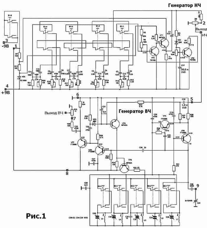
The diagram of the universal combined generator - GUK-1 is shown in Figure 1. The device includes two generators, a low-frequency generator and an RF generator.
TECHNICAL DETAILS
1. The frequency range of the HF generator from 150 kHz to 28 MHz is covered by five sub-bands with the following frequencies:
• 1 sub-band 150 - 340 kHz
• II 340 - 800 kHz
• III 800 - 1800 kHz
• IV 4.0 - 10.2 MHz
• V 10.2 - 28.0 MHz
2. HF setting error no more than ± 5%.
3.The HF generator provides smooth adjustment of the output voltage from 0.05 mV to 0.1 V.
4. The generator provides the following types of work:
a) continuous generation;
b) internal amplitude modulation with a sinusoidal voltage with a frequency of 1 kHz.
5. The modulation depth is not less than 30%.
6. The output impedance of the HF generator is not more than 200 Ohm.
7. LF generator generates 5 fixed frequencies: 100 Hz, 500 Hz, 1 kHz, 5 kHz, 15 kHz.
8. Permissible deviation of the frequency of the LF generator is not more than ± 10%.
9. The output impedance of the LF generator is not more than 600 ohms.
10. The output voltage of the LF is continuously adjustable from 0 to 0.5 V.
11. Self-heating time of the device - 10 minutes.
12. The device is powered by a 9 V "Krona" battery.
The LF generator is assembled on transistors VT1 and VT3. The positive feedback necessary for the generation of generation is removed from the resistor R10 and fed into the base circuit of the transistor VT1 through the capacitor C1 and the corresponding phase-shifting circuit selected by the switch B1 (for example, C2, C3, C12.). One of the resistors in the chain is a trimmer (R13), with which you can adjust the frequency of generating a low-frequency signal. Resistor R6 sets the initial bias based on the transistor VT1. A circuit for stabilizing the amplitude of the generated oscillations is assembled on the VT2 transistor. The sinusoidal output voltage through C1 and R1 is fed to the variable resistor R8, which is the regulator of the output signal of the LF generator and the regulator of the amplitude modulation depth of the HF generator.
The RF generator is implemented on transistors VT5 and VT6. From the generator output through C26, the signal is fed to an amplifier assembled on transistors VT7 and VT8. An RF signal modulator is assembled on transistors VT4 and VT9. The same transistors are used in the output signal amplitude stabilization circuit. It would not be bad for this generator to make an attenuator, either T or P type. Such attenuators can be calculated using the appropriate T-attenuator and P-attenuator calculators. That's all. Goodbye. K.V.Yu.
The drawing in LAY format was kindly provided by Igor Rozhkov, for which I express my gratitude to him for myself and for those who will find this drawing useful.
| Video (click to play). |
The given archive contains Igor Rozhkov's file for an industrial amateur radio generator with five HF bands - GUK-1. The board is shown in * .lay format and contains a revision of the circuit (the sixth switch for the range 1.8 - 4 MHz), previously published in the journal Radio 1982, No. 5, p.55
Download the drawing of the printed circuit board.

