In detail: generator ford focus 2 do-it-yourself repair from a real master for the site my.housecope.com.
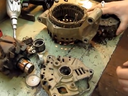
We disassemble the Ford Focus 2 generator to check and replace the voltage regulator with a brush holder and a rectifier unit.
Using the "7" head, unscrew the four nuts securing the generator casing.
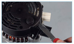

With a knife we clean the sealant from the inside of the casing ...
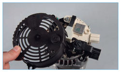

… And remove the generator casing.
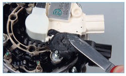

We clean the nut that secures the generator output from the sealant.
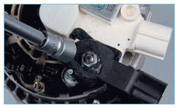

Turn off the nut with the "10" head ...
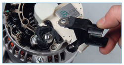

... and remove the generator output.
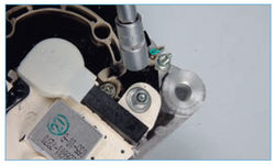

Using the "8" head, unscrew the nut for fastening the brush holder with a voltage regulator.
Remove the washer under the nut.
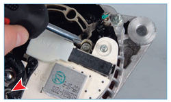

Using a Phillips screwdriver, unscrew the two screws securing the brush holder with a voltage regulator.
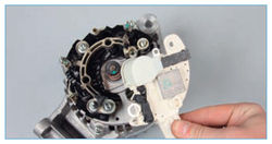

Remove the brush holder with voltage regulator assembly.
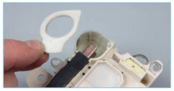

Remove the protective film from the brush holder.

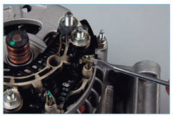

Use a screwdriver to unclench the three outputs of the rectifier unit.
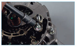

Using the "8" head, unscrew the two nuts securing the rectifier unit.
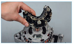

We remove the rectifier unit.
To check the rotor winding short circuit to ground ...
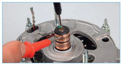

… We connect the tester probes (in ohmmeter mode) to the slip ring and the rotor shaft.
The tester should show infinity, otherwise the winding is shorted to ground and you need to replace the rotor or generator.
To check if the rotor winding is broken ...
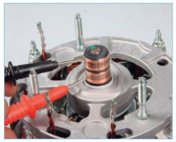

… We connect the tester probes (in ohmmeter mode) to the slip rings.
If the tester shows infinity, then there is an open circuit in the winding and you need to replace the rotor or generator.
We inspect the stator windings.
There should be no traces of overheating on the insulation of the windings, which is the result of a short circuit in the valves of the rectifier unit. If the windings show signs of overheating, the stator or generator must be replaced.
To check for a break in the stator windings ...
| Video (click to play). |
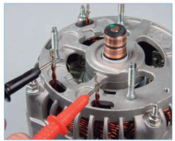

… We connect the tester probes (in ohmmeter mode) to the winding terminals.
If the tester shows infinity, then there is an open circuit in the winding and you need to replace the stator or generator.
Similarly, we check the rest of the stator windings.
To check the short circuit of the stator winding to ground ...
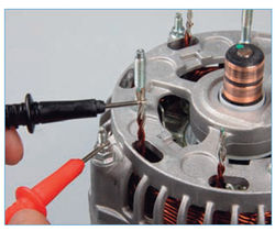

… We connect the tester probes (in ohmmeter mode) to the winding terminal and the generator case.
The tester should show infinity, otherwise the winding is shorted to ground and the stator or generator must be replaced.
Similarly, we check the rest of the windings.
To check the short circuit in the positive diodes of the rectifier unit ...
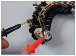

... the "plus" of the tester (in ohmmeter mode) is connected to the output of the generator, and the "minus" - to one of the outputs of the rectifier unit.
The tester should show infinity. If the tester indicates a circuit is present, one or more positive diodes are punctured.
To check the short circuit in the negative diodes, we connect the "plus" of the tester to one of the terminals of the rectifier unit, and the “minus” - to the bottom plate of the rectifier unit. The tester should show infinity. If the tester indicates a circuit is present, one or more negative diodes are punctured. In both cases, the rectifier unit must be replaced.
To test the voltage regulator ...
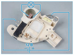

... we connect a lamp (1-3 W, 12 V) to the brushes, and a DC power supply to the brush holder terminals, first with a voltage of 12 V, and then 15-16 V.
In the first case, the lamp should be on, in the second - not. If the lamp is on in both cases - there is a breakdown in the regulator, if it is not lit - there is an open or broken contact between the brushes and the terminals of the voltage regulator. In both cases, the regulator must be replaced.
We assemble the generator in the reverse order. At the same time, crimping the terminals of the rectifier unit at the terminals of the stator winding ...
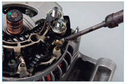

... we solder the places of their connection.
Before installing the brush holder, put the protective film of the brushes on the back cover of the generator. Having sunk the brushes, we install the brush holder in place ...
The original source of content - WiKi of the site of the magazine "Za Rulem"
REMOVING THE GENERATOR
We remove the generator for repair or replacement if it fails.
Disconnect the terminal of the wire from the negative terminal of the battery.
Remove the accessory drive belt (see "1.3.6. Ford Focus II. Checking the condition and replacing the accessory and air conditioning drive belts. Replacing the spark plugs").
Remove the power steering reservoir without disconnecting the hoses from it and move the reservoir to the side (see "8.6. Ford Focus II. Removing the reservoir and removing air from the power steering hydraulic drive").
Pressing the latch, disconnect the wiring block from the generator connector.
Remove the protective cap.
Using the "10" head, unscrew the nut that secures the wire tip to the generator output.
We remove the tip of the wire from the output of the generator.
Using the "15" head, unscrew the bolt of the lower mounting of the generator.
With the same tool, unscrew the bolt and nut of the upper mounting of the generator.
We take out the bolt ...
… And remove the power steering reservoir bracket.
We move the generator off the stud ...
… And take the generator out of the engine compartment.
Generator marking
Install the generator in reverse order.
DISASSEMBLY OF THE GENERATOR
We disassemble the generator to check and replace the voltage regulator with a brush holder and a rectifier unit.
Using the "7" head, unscrew the four nuts securing the generator casing.
With a knife we clean the sealant from the inside of the casing ...
… And remove the generator casing.
We clean the nut that secures the generator output from the sealant.
Turn off the nut with the "10" head ...
... and remove the generator output.
Using the "8" head, unscrew the nut for fastening the brush holder with a voltage regulator.
Remove the washer under the nut.
Using a Phillips screwdriver, unscrew the two screws securing the brush holder with a voltage regulator.
Remove the brush holder with voltage regulator assembly.
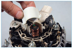
Remove the protective film from the brush holder.
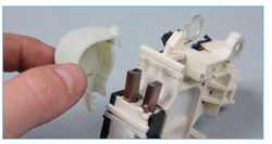
Remove the cover of the brushes.
Use a screwdriver to unclench the three outputs of the rectifier unit.
Using the "8" head, unscrew the two nuts securing the rectifier unit.
We remove the rectifier unit.
To check the rotor winding short circuit to ground ...
… We connect the tester probes (in ohmmeter mode) to the slip ring and the rotor shaft.
The tester should show infinity, otherwise the winding is shorted to ground and you need to replace the rotor or generator.
To check if the rotor winding is broken ...
… We connect the tester probes (in ohmmeter mode) to the slip rings.
If the tester shows infinity, then there is an open circuit in the winding and you need to replace the rotor or generator.
We inspect the stator windings.
There should be no traces of overheating on the insulation of the windings, which is the result of a short circuit in the valves of the rectifier unit. If the windings show signs of overheating, the stator or generator must be replaced.
To check for a break in the stator windings ...
… We connect the tester probes (in ohmmeter mode) to the winding terminals.
If the tester shows infinity, then there is an open circuit in the winding and you need to replace the stator or generator.
Similarly, we check the rest of the stator windings.
To check the short circuit of the stator winding to ground ...
… We connect the tester probes (in ohmmeter mode) to the winding terminal and the generator case.
The tester should show infinity, otherwise the winding is shorted to ground and the stator or generator must be replaced.
Similarly, we check the rest of the windings.
To check the short circuit in the positive diodes of the rectifier unit ...
... the "plus" of the tester (in ohmmeter mode) is connected to the output of the generator, and the "minus" - to one of the outputs of the rectifier unit.
The tester should show infinity. If the tester indicates a circuit is present, one or more positive diodes are punctured.
To check the short circuit in the negative diodes, we connect the "plus" of the tester to one of the terminals of the rectifier unit, and the “minus” - to the bottom plate of the rectifier unit. The tester should show infinity. If the tester indicates a circuit is present, one or more negative diodes are punctured. In both cases, the rectifier unit must be replaced.
To test the voltage regulator ...
... we connect a lamp (1-3 W, 12 V) to the brushes, and a DC power supply to the brush holder terminals, first with a voltage of 12 V, and then 15-16 V.
In the first case, the lamp should be on, in the second - not. If the lamp is on in both cases - there is a breakdown in the regulator, if it is not lit - there is an open or broken contact between the brushes and the terminals of the voltage regulator. In both cases, the regulator must be replaced.
We assemble the generator in the reverse order. At the same time, crimping the terminals of the rectifier unit at the terminals of the stator winding ...
... we solder the places of their connection.
Before installing the brush holder, put the protective film of the brushes on the back cover of the generator. Having sunk the brushes, we install the brush holder in place ...
... and install the brush cover.
We disassemble the generator to check and replace the voltage regulator with a brush holder and a rectifier unit.
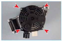

Using the "7" head, unscrew the four nuts securing the generator casing.


With a knife we clean the sealant from the inside of the casing ...


… And remove the generator casing.


We clean the nut that secures the generator output from the sealant.


Turn off the nut with the "10" head ...


... and remove the generator output.


Using the "8" head, unscrew the nut for fastening the brush holder with a voltage regulator.
Remove the washer under the nut.


Using a Phillips screwdriver, unscrew the two screws securing the brush holder with a voltage regulator.


Remove the brush holder with voltage regulator assembly.


Remove the protective film from the brush holder.


Use a screwdriver to unclench the three outputs of the rectifier unit.


Using the "8" head, unscrew the two nuts securing the rectifier unit.


We remove the rectifier unit.
To check the rotor winding short circuit to ground ...


… We connect the tester probes (in ohmmeter mode) to the slip ring and the rotor shaft.
The tester should show infinity, otherwise the winding is shorted to ground and you need to replace the rotor or generator.
To check if the rotor winding is broken ...


… We connect the tester probes (in ohmmeter mode) to the slip rings.
If the tester shows infinity, then there is an open circuit in the winding and you need to replace the rotor or generator.
We inspect the stator windings.
There should be no traces of overheating on the insulation of the windings, which is the result of a short circuit in the valves of the rectifier unit. If the windings show signs of overheating, the stator or generator must be replaced.
To check for a break in the stator windings ...


… We connect the tester probes (in ohmmeter mode) to the winding terminals.
If the tester shows infinity, then there is an open circuit in the winding and you need to replace the stator or generator.
Similarly, we check the rest of the stator windings.
To check the short circuit of the stator winding to ground ...


… We connect the tester probes (in ohmmeter mode) to the winding terminal and the generator case.
The tester should show infinity, otherwise the winding is shorted to ground and the stator or generator must be replaced.
Similarly, we check the rest of the windings.
To check the short circuit in the positive diodes of the rectifier unit ...


... the "plus" of the tester (in ohmmeter mode) is connected to the output of the generator, and the "minus" - to one of the outputs of the rectifier unit.
The tester should show infinity. If the tester indicates a circuit is present, one or more positive diodes are punctured.
To check the short circuit in the negative diodes, we connect the "plus" of the tester to one of the terminals of the rectifier unit, and the “minus” - to the bottom plate of the rectifier unit. The tester should show infinity.If the tester indicates a circuit is present, one or more negative diodes are punctured. In both cases, the rectifier unit must be replaced.
To test the voltage regulator ...


... we connect a lamp (1-3 W, 12 V) to the brushes, and a DC power supply to the brush holder terminals, first with a voltage of 12 V, and then 15-16 V.
In the first case, the lamp should be on, in the second - not. If the lamp is on in both cases - there is a breakdown in the regulator, if it is not lit - there is an open or broken contact between the brushes and the terminals of the voltage regulator. In both cases, the regulator must be replaced.
We assemble the generator in the reverse order. At the same time, crimping the terminals of the rectifier unit at the terminals of the stator winding ...


... we solder the places of their connection.
Before installing the brush holder, put the protective film of the brushes on the back cover of the generator. Having sunk the brushes, we install the brush holder in place ...
The article will focus on replacing a generator on a Ford Focus 2 car with engines of 1.6, 1.8, 2.0 liters, signs of a device malfunction, checking its performance and replacing the brush assembly.
On Ford Focus 2 cars, the on-board network is powered with the engine running and the battery is recharged from a three-phase alternator, which is installed on all modifications of this car.
The conversion of alternating current into direct current is carried out by a rectifier unit, which is part of the generator's design, and the voltage stabilization and maintenance at the required level is performed by an electronic voltage stabilizer.
In addition, the ECU of the power plant affects the operation of the unit. This allows the generator to function properly under different conditions.
It is driven by the crankshaft of the power plant through a belt drive, which is also used to drive other attachments (air conditioning). The unit is cooled by an impeller mounted on the rotor.
The generator on Ford Focus 2 is considered maintenance-free due to the use of closed-type bearings on the rotor, the resource of which is designed for the entire period of operation of the car.
In reality, the device is not very reliable and breaks down quite often.
Symptoms of a malfunction are:
- Increased noise from under the hood (squeal, squeak);
- Lack of battery recharge;
- Lack of electricity when using electrical equipment in a car (the headlights shine weakly, and when they are turned on, the warning lamps on the dashboard dim).
At the same time, despite the fact that the generator is connected to a self-diagnosis system, a malfunction signal is not always displayed on the on-board computer. In this case, the breakdown can be detected empirically.
Before removing the generator from the Ford Focus 2 for replacement or repair, you should first make sure it is faulty. The verification technology is very simple and fast.
Before diagnosing the functionality, it is necessary to loosen the positive terminal on the battery.
- we start the engine;
- wait until the turnover stabilizes;
- turn on the headlights;
- on the running engine, remove the positive terminal from the battery.
If the generator is in good working order, the power plant should not stop, on the contrary, its speed should increase slightly, since the ECU will correct the operation of the motor in order to provide the on-board network with energy.
Stopping the unit after removing the terminal will indicate a malfunction of the generator and the need to repair or replace it. And for this, the unit must be removed from the car, which turns out to be not so easy.
You can use the official instructions, which are presented below, but it does not reflect all the subtleties and nuances of the work, and therefore it is more suitable for acquaintance than as a detailed guide that is understandable to everyone.
The Ford Focus 2 uses several modifications of power plants with different design features that affect the algorithm of work during removal.
On engines with a volume of 1.4 and 1.6 liters, the generator is located in the upper part, which somewhat simplifies dismantling.
As an example, consider the technology for removing a node from a Ford Focus 2 equipped with a 1.6-liter unit.
To complete the work you will need:
- Keys for 8, 10, 12 and 13 (better - heads of the indicated sizes with extensions and a wrench equipped with a ratchet mechanism);
- Flat screwdriver;
- Bit Torx E10.
These tools will be enough to get the job done. Dismantling is carried out on a cold engine.
Inspect the device for external damage. Smell, if it smells burnt, then most likely the wiring is burnt out.
Installation of a repaired or new unit is performed in the following sequence:
- First, the stud and nut are screwed in (Torx head 10, head 15);
- We put on the plastic bracket that holds the power steering reservoir;
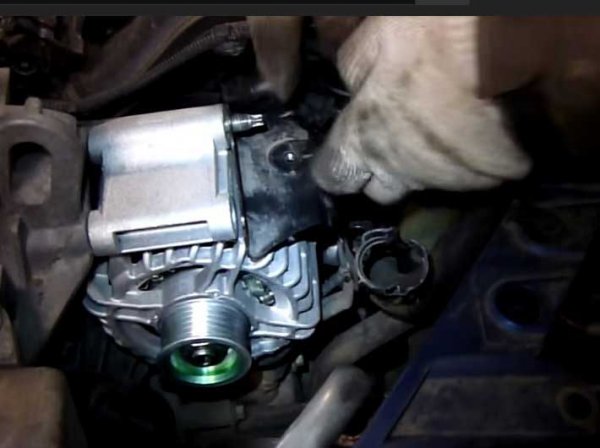
- Insert and tighten the lower bolt under the pulley;
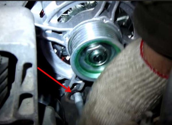
- We bait and tighten the upper bolt (to the left of the hairpin);
- Install the belt;
- We connect the connector and the generator wire. In the latter case, we use a nut for 10;
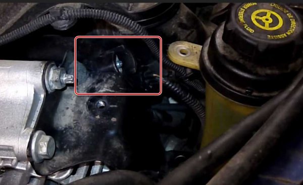
- We put the coolant reservoir in its regular place;
- We put a pipe clamp;
- We install the power steering barrels;
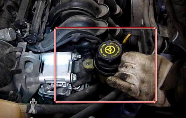
- We connect the power wire;
- Do not forget to install all the hoses in their places;
- We start the car and check the generator.
You need to choose a new generator by the VIN code of the car. The original products are manufactured by the Italian company DENSO.
The sticker must indicate that this is FORD, the amperage and original engineering code - 115 IM.
Difficulty installing the generator can cause the drive belt to land in place, since there is no tension roller on the 1.6-liter Ford Focus engine. Therefore, the installation of the drive is carried out using special tools that come with the original belt.
On Ford Focus 2 1.8 and 2.0 liter engines, the location of the generator differs from the 1.6-liter engine, and when dismantling, you cannot do without a viewing hole or overpass.
To carry out work from the tools, you will need all the same keys and heads for 8, 10, 12 and 13, as well as a screwdriver and an open-end wrench for 19.
Let us consider the algorithm of work on removal using the example of a 1.8-liter unit. Some of the work is done on top of the engine, and some on the bottom.
- We install the car on the pit;
- Remove the plastic protection from the engine;
- Remove the terminal from the battery;
- With a key 17 (19), we shift the tension roller towards the cab and remove the drive belt;
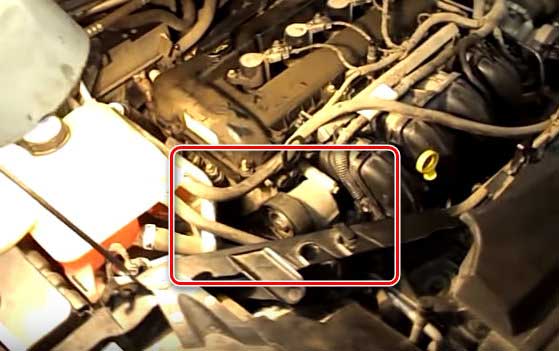
- Using a 10 key, unscrew 3 roller fasteners, 1 - at the top (short, so mark it) and 1 - at the bottom under the engine, remove them. Pay attention, there are 2 bolts at the bottom, but so far only one is unscrewed;
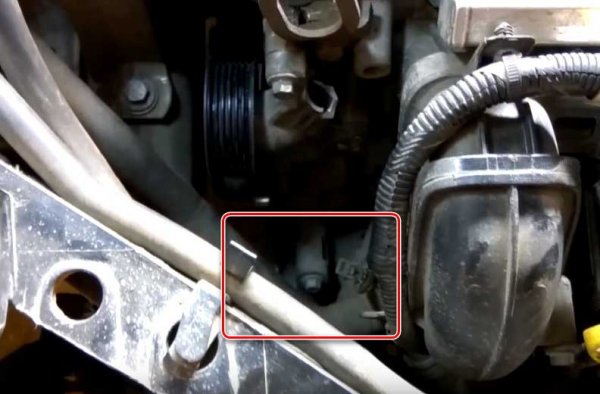
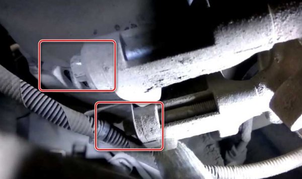
- We unscrew the bracket fastening bolt, which is used to attach the air conditioning pipe to the body, which goes to the air conditioner radiator. This is necessary so that you can then bend the tube and get the generator;
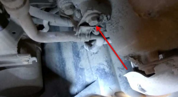
- Turn off the chip using a flat screwdriver;
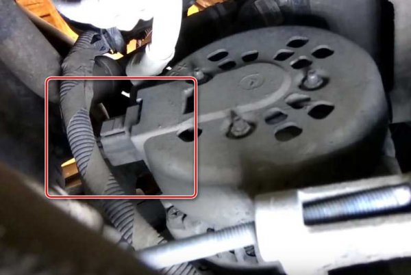
- Unscrew the second lower mounting bolt;
- After the knot drops down a little, we turn it, which will allow us to get to the wiring block and the nut for fixing the power cable. We disconnect the block and the power wire with a 13 head;

- Taking the air conditioner branch pipe to the side, we take out the generator.
Installation of the assembly is carried out in the reverse order. Do not mix up the bolts.
Similarly, assembly and disassembly is carried out on a 2.0-liter unit.
On engines with a volume of 1.8 and 2.0 liters, the operation is convenient in that special equipment is not required to land the drive belt due to the presence of a tension roller.
The most common breakdowns for which a generator has to be removed are wear on the graphite brushes and rotor bearings. These malfunctions can be attributed to mechanical ones and you can fix them yourself.
To replace the brush assembly, you only need keys 8 and 10, as well as a flat and Phillips screwdriver.
The brush assembly is located under the rear cover, and a complete disassembly of the generator is not required.To replace the brushes, you need to dismantle the back cover, and for this:
- We unscrew the second nut on the hairpin, to which the power cable is connected;
- With a key for 8, we twist the three nuts securing the cover;
- Use a screwdriver to unscrew the terminal jumper screw;
- Remove the cover.
After dismantling the cover, it remains to unscrew the three screws of the brush assembly, remove it, install a new one and put everything back together.
The whole process of work is described in the official instructions.
In addition to the brushes, removing the back cover, you can also change the voltage regulator and rectifier bridge.
As for the bearings, you will have to completely disassemble the assembly to replace them.
Malfunctions associated with the electrical part - winding breaks, short circuits and other breakdowns are repaired only in a specialized service.
In a number of cases, such malfunctions cannot be eliminated and the generator is simply replaced with a new one.
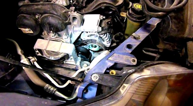
Remove the generator from the car (see subsection 8.2.1.).
1. Unscrew the nut and remove the shim.
2. Unscrew the fastening nut, keeping the pulley from turning (see recommendation), and remove the pulley together with the fan impeller. Remove the key from the armature shaft.
The manufacturer recommends a special device to keep the pulley from turning.
If there is no adaptation, you can do this:
1. Put the alternator belt on the pulley and on top of it - another belt with a larger section so as not to jam the pulley.
2. Clamp the pulley with belts in a vice and unscrew the retaining nut.
3. Unscrew the nut and disconnect the capacitor wire from the generator terminal "ЗО".
4. Unscrew the screw and remove the capacitor.
5. Disconnect the block with the wire from the brush holder.
6. Remove the two screws securing the brush holder.
7. Take out the brush holder with voltage regulator.
8. Remove the four mounting nuts and.
9. . remove the four tie bolts.
10. Using a puller, remove the drive end cover from the armature shaft.
11. Remove the spacer sleeve from the armature shaft.
12. Remove the armature from the manifold side cover.
13. Remove the three retaining nuts and disconnect the stator leads from the rectifier unit.
14. Remove the three bolts securing the rectifier unit and stator leads with insulating pads.
15. Remove the stator from the cover.
16. Unscrew the nut securing the "ЗО" terminal.
17. Use a screwdriver to press the tab on the plug inside the block and push the plug with the wire into the cover. In this case, the plastic block remains on the lid.
18. Remove the rectifier unit from the cover.
19. To replace the bearing in the cover from the drive end, unscrew the four fastening nuts, remove the bolts and.
twenty. . remove the inner and outer bearing retaining washers. Then press the bearing out of the cover using a suitable mandrel. Press the new bearing in flush with the surface of the cover. Force should only be applied to the outer ring of the bearing.
21. To replace the manifold side bearing, press it off the armature shaft with a puller. Press on the new bearing until it stops, applying force only to the inner ring of the bearing.
22. Check if the voltage regulator is working properly. Connect a 12 V test lamp to the brushes. Apply voltage 12 V: “+” to the output, and “-” to the “mass” of the brush holder. The control lamp should light up.
23. Increase the voltage to 15-16 V - the lamp should go out. If the lamp does not go out or does not light up at 12 V, replace the regulator with a brush holder.
24. Check the ease of movement of the brushes in the brush holder and their protrusion. If the brushes protrude from the brush holder by less than 5 mm, replace the voltage regulator with the brush holder. If you find chips or cracks on the brushes, replace the regulator.
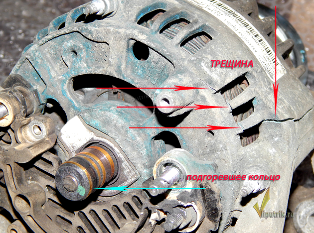
25. Inspect the slip rings. If they have seizures, risks, scratches, traces of wear from brushes, etc., the rings must be sanded. If the damage to the rings cannot be removed with sandpaper, grind the rings on a lathe, removing a minimum layer of metal, and then sand.
26.Check the resistance of the rotor winding with an ohmmeter (tester) by connecting it to the slip rings. If the ohmmeter shows “infinity”, then there is an open circuit in the windings and the rotor needs to be replaced.
27. Check with a test lamp if there is no short circuit of the winding on the rotor housing. Connect a test lamp to the storage battery. Connect one of the wires to the rotor body, and the second one to the rings in turn.
In both cases, the lamp should be off. If the lamp lights up, then the winding is closed: it is necessary to replace the rotor.
28. Inspect the stator. On the inner surface of the stator there should be no traces of the armature rubbing against the stator. If there is wear, the bearings or generator covers must be replaced.
29. Check if there is an open circuit in the stator winding. Connect a test lamp to the storage battery. Connect a test lamp to the winding terminals one by one. In all three cases, the lamp should be on. If the lamp does not light up, there is a break in the winding. Replace stator or winding.
30. Check if there is no short circuit of the stator windings to the housing. Connect a test lamp to the storage battery. Connect the lamp to the terminal of the stator winding and the wire from the power source to the stator housing. If the lamp lights up, then there is a short circuit: it is necessary to replace the stator or winding.
31. Check the diodes of the rectifier unit using a 12 V test lamp and a storage battery. To check the short circuit in positive and negative diodes, connect the “+” batteries through the test lamp to the terminal “30” of the generator, and “-” of the battery to the generator case. If the lamp lights up, then there is a short circuit in the diodes and the unit must be replaced (see the recommendation).
Operation recommendation 31
You can check the rectifier unit without removing the generator from the car. To do this, disconnect the wires from the battery and the generator, and also remove the block with the wire from the output of the voltage regulator.
32. To check the positive diodes, connect the “+” of the storage battery through the test lamp to the terminal “30” of the generator, and “-” of the storage battery - to one of the bolts of the rectifier unit. If the lamp is on, then there is a short circuit in the positive diodes: the unit must be replaced.
33. To check negative diodes, connect the “+” of the battery through the test lamp to one of the rectifier unit mounting bolts, and “-” of the battery - to the generator case. If the lamp lights up, then there is a short circuit in the negative diodes: the unit must be replaced (see warning).
Step 33 warning
34. To check additional diodes, connect the “+” of the storage battery through the test lamp to the terminal “61” of the generator, and “-” of the storage battery - to one of the bolts of the rectifier unit. If the lamp lights up, then there is a short circuit in the additional diodes. The block needs to be replaced.
35. Inspect the drive end cover of the generator. If there are cracks, especially at the generator mounting points, replace the cover. Measure the diameter of the bearing seat in the drive end cover. If the bearing bore is deformed or exceeds 42 mm in diameter, replace the cover.
36. Check the ease of rotation of the bearings. If, during the rotation of the bearings, play appears between the rings, rolling or jamming of the rolling elements, the bearings must be replaced. Also replace bearings with damaged wear rings or grease leaks.
37. Inspect the generator cover from the slip ring side. If there is damage or worn out the bearing seat ring, replace the cover.
38. The serviceability of the capacitor can be checked with a megohmmeter or a tester (on a scale of 1–10 megohm). Connect one tester probe to the capacitor terminal and the other to the generator body. Before connecting, the device shows “infinity”. At the moment of connection, the resistance should decrease, and then return to its previous position: in this case, the capacitor is operational. The defective capacitor must be replaced.
39.Reassemble the generator in the reverse order of disassembly. Please note: the holes in the covers for mounting the generator must be aligned (according to the manufacturer's data, the deviation from the alignment should not exceed 0.4 mm). Tighten the alternator pulley retaining nut to a torque of 39–90 N / m (3.9–9.0 kgf / m)
Watch an interesting video on this topic
| Video (click to play). |

