In detail: generator ford mondeo 3 do-it-yourself repair from a real master for the site my.housecope.com.
Generator removal report!
1. We jack up, unscrew the right front wheel, put it on a support for insurance. DO NOT LEAVE on the jack !! My friend's car fell from the jack on his head - he barely survived.
2. We open the hood, remove the decorative cover from the engine, remove the terminal from the battery (do not forget to stock up on the code for the radio - it will be locked).
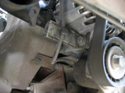
3. We look to the left of the engine, closer to the engine shield, a generator is visible in space: (sorry, bad photo, but the location is clear)
4. From the bottom, in the wheel niche, unscrew 3 bolts (10 and 8) and remove the dirt apron.
5. The following view opens:
6. The roller has a 15 hexagon (I don't remember exactly). We put the head on it, turn it clockwise through the extension cord as far as it will turn out (30 degrees), while it moves up to the right:
7. Holding the ratchet with my knee, I removed the belt from the roller, looking into the engine compartment from above. The first time I removed it from the generator pulley itself, but this is inconvenient
8. Throwing off the belt from the roller, you can easily remove it from the genes. So, they removed the belt, then:
9. Remove the plastic L-shaped cooling tube from the generator. There are two latches, it is removed by hand, but the third place of its attachment is the plate on the lower outer bolt of the generator, snap it off, there is a piston type:
10. Nearby, on the last photo, you can see a wire snapped to the bracket - you can shoot, you can not. The bracket itself can be easily removed with a half-unscrewed bolt, but until you see how, it is unlikely to work. In general, decide for yourself.
11. Unscrew the two bottom bolts. There, a 13 wrench. I used a ratchet and a short extension. It turned out to be more convenient for me from above, because the bottom of my ratchet was not able to work:
| Video (click to play). |
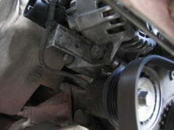
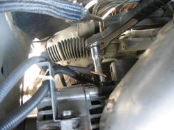
12... We remove all the wires (preferably together with the bracket) from the upper bolt, having previously released it on the heels of the revolutions. Everything is visible there, you will understand. Simply click the bracket upwards. Take everything aside. Try to unscrew the nut by 10, with which a thick wire from the battery is screwed to the gene. It's next to the 3-pin connector. You can safely crawl with a ratchet without an extension cord.
13. I didn’t succeed in removing the connector blindly either the first or the second time - if you don’t see it, then you don’t understand how to snap it off. I completely removed the gene and removed the connector already in the light. There is a crack, I put the blade of my penknife into it, it comes off.
14. So, unscrew the top bolt, catch the generator. It is quite heavy, 5 kilograms, strives to slip out and fall down, breaking the wires. Be careful.
15. After tormenting over the top, having washed, remembering the relatives of the designers, we pull out the gene. There are no recommendations here - see for yourself. I will say right away that it pushes back much easier - gravity helps
16. And this is me and my trophy (Like, hunted a lion in Africa)
Thanks to all,
Sincerely,
Alexey Doc Pribytkov.
P.S: By the way, I must warn you: DO NOT SCUT THE BELT BUCKLE FENDER. I specially tied a rag, otherwise the pants fall without a belt, it's hot in the jacket, and the buckle can scratch the wing
I will add my 5 kopecks about the removal of the genes (regarding cars with V6)
Firstly, as Alexei already said, in no case leave the car on a standard jack. I was in a hurry, I left it for the first time, only got out from under the car, and she sank down, (licking the thread on the jack nut).
Further, the operations are about the same, except for the following:
The V6 tensioner is squeezed out of the engine compartment, for which a 4-sided part of the ratchet (like size 3/8) is inserted into it, the belt is squeezed out and removed.
In the engine compartment, no more operations are available, everything is done from below, either through the wheel arch or from the pit.
Next, unscrew the genes bolts. Space there is catastrophically small, so I first removed the upper bolt, with which I have to suffer for a long time, then 2 lower ones. It's easier with them. And finally, the generator cannot be removed from above, it is removed through the wheel housing, after having thrown off the bone.
So by the way, and TIS advises.
Andry - Andrey
FM3 2.5 03 onwards hatch Jatco Ghia
04.02.2017 722
As a result, after the battery is completely discharged, your car will become stationary, and what is most annoying, this can happen at the most inopportune moment, for example, at night somewhere outside the city.
- Wear of brushes;
- Pulley worn or damaged;
- Short circuit in the stator winding;
- Damage to the voltage regulator;
- Backlash or destruction of the bearing;
- Break in the charging circuit wiring;
- Damage to the rectifier (diode bridge).
Today at Ford Master I will tell you how to perform generator repair Ford Mondeo 3 at home, this will save you the cost of buying a new generator.
- Puller;
- Screwdrivers;
- Hacksaw blade;
- A set of keys;
- Soldering iron;
- Spare parts: pulley, diode bridge, new brushes, bearing.
- The first step is to remove the generator.
- Next, you should clean the generator from dirt and dust. After you need to unscrew the pulley, if you do not have the necessary tool in order to unscrew the pulley, you can get out of the situation by contacting the nearest service station.
- Next, we proceed to unscrewing the studs, we use the key to “8” for this.
- The next step was to dismantle the diode bridge, a difficulty arose here, since spot welding was used in the manufacture of the generator, and it had to be cut down. You can saw with a Dremel, a file or a grinder, in this case a hacksaw blade was used. Also, in order to remove the diode bridge, you need to drill two rivets from the back cover.
- We dismantle the collector using a chisel, put it under spot welding, then carefully slightly separate the wire from the slip ring.
- Carefully align the wires and remove them using a slotted screwdriver.
- We remove the slip rings in turn.
- Then we remove the rear bearing, in my case it went pretty tight.
- Using a puller, press out the front bearing.
- We prepare bearings. We put the required amount of lubricant and proceed to assembly. We install the front bearing on the armature shaft. By the way, it is installed quite simply, practically by hand, after everything is assembled it will be clamped with a clutch.
Attention! After the collector rings have been pressed in and the armature wires have been soldered, I recommend walking with a cutter on a lathe for centering.
- Using a soldering iron, we solder the diode bridge to the stator winding, before that we carefully tin all the soldering points.
Subsequent assembly is carried out in reverse order.
Removing the alternator on a Ford Mondeo is a complicated and time-consuming procedure that requires time and certain skills. The generator is removed, as a rule, in the event of a malfunction or other cases requiring diagnostics or intervention.
Today I will share with you, dear visitors my.housecope.com/wp-content/uploads/ext/520, a secret about how to properly and quickly remove a generator from a Ford Mondeo third generation, but first, a few words about the tool and safety.
| Video (click to play). |
In order to remove the generator Ford Mondeo 3 you need to prepare:
We remove the generator on a Ford Mondeo 3 with our own hands
1. Install a jack and jack the front right wheel, then remove it. Install safety stops in case the jack fails.
2. Next, you need to open the hood and remove the decorative plastic trim from the engine.
3. De-energize the car, to do this, remove the "negative" terminal from the battery.
4. In the wheel arch, unscrew the three bolts at "10" and "8", and then remove the plastic engine mudguard located in the wheel opening. In the end, you get this:
5. Take the hex at “15”, then put the head on it and using the extension, turn the roller clockwise about 30 °, while it will move up to the right.
6. Remove the belt from the roller, and then from the generator.
7. Next, in turn, dismantle the plastic tube for cooling the L-shaped generator. Two latches that are there are removed by hand, the third fastener is a plate located on the outer bolt of the generator located below.
8. Unscrew the two bottom bolts with a 13 wrench with a ratchet and extension.
9. Loosen the top bolt and remove all wires (it will be better if together with the entire bracket). The bracket itself is removed with a simple upward movement, then take it all to the side.
10. Unscrew the nut on "10", which secures the generator power. It is located near the three-pin connector, it is not difficult to get there even without an extension cord.
11. It remains to unscrew the top bolt and remove our generator. Be careful and careful, the "detail" is quite weighty, no less than five kilograms, if you miss it or slip out, then problems will be added, for example, if you tear off the wires or damage the case.
That's all! We shoot, rejoice, carry out the planned activities and install in the reverse order.
Self-repair of the generator and regulator
To remove the cover (2) of the bosch generator, unscrew the three Phillips screws (1), remove the wire b + from the threaded bolt (3) and push off the two retaining lugs (arrows).
The voltage regulator (2) is secured with two Phillips head screws (1). Position (3) denotes the rotor axis.
On the removed voltage regulator ((4), the illustration shows a new design), the length of the brushes (2) is indicated by arrows. Position (1) shows the contacts of the voltage regulator, (3) are the fastening bolts.
The illustration shows the measurement of the length of sliding electrographite contacts on a removed voltage regulator from bosch of an older design: the brushes should not be shorter than a = 5 mm.
Usually the generator does not require repair, except when replacing the generator brushes. More serious damage cannot be repaired with home remedies.
Checking the charging voltage
- Connect a volmeter between the generator thick red wire terminal and ground.
- Leave the engine running at medium speed.
- If the voltage regulator is working properly, the voltmeter should read 13.3 to 14.6 V.
- If not, check the brushes or replace the regulator.
- Otherwise, the generator itself is faulty.
- Disconnect the negative battery cable.
- Bosch alternators: remove battery cover at rear (where fitted).
- Disconnect the regulator from the generator. To do this, remove the two screws.
- Fold back the regulator so that the carbon brushes do not stick in the holders.
- Measure the protrusion of the brushes.
- The length of the new brushes is 13 mm; minimum length 5 mm.
- Valeo alternators: Unscrew both regulator fixing screws on the rear of the alternator.
- Pull out the regulator.
- Measure the length of the protruding brushes.
- If the remaining length is 5 mm, the brushes are worn out.
- Valeo generator brushes cannot be purchased separately; it is necessary to change the entire regulator.
Replacing the brushes on the new generation of bosch generators is no longer possible - therefore carbon brushes are no longer sold as spare parts. If they are worn out, the entire regulator should be replaced.The same can be said about the valeo generator; carbon brushes are not sold as spare parts - you need to buy a new voltage regulator if the old brushes are worn out.
However, such replacement is possible for older generation Bosch generators. This will require a soldering iron, solder and, in addition, knowledge of soldering.
- Remove the voltage regulator as described above.
- Unsolder the stranded flexible wires, pull out the carbon brushes.
- Remove pressure springs from old brushes and put on new ones.
- Solder stranded flexible wires.
- At the same time, apply a little tin and work quickly so that the wires do not suck in a lot of tin. Otherwise, they will become tough.
Hint: if the brushes are removed, you can check the copper slip rings at the same time (brushes walk on them). If deep traces of running-in are found on them, then you need to grind and polish them in an auto electrician's workshop.
- Disconnect the ground wire from the battery, otherwise there is a great risk of short circuit.
- 4-cylinder models: Remove the front pivot cover (where fitted) on the toothed belt guard.
- 5-cylinder models: remove the underbody protection from the engine compartment.
- 4- and 5-cylinder models: Disconnect alternator wires.
- Disconnect the earth cable, where available.
- Unscrew the clamping bolt on the alternator shim.
- Loosen and remove the V-belt or poly-V-belt
- Loosen and remove the hinge bolt while holding the generator.
- 6-cylinder models: remove the underbody protection from the engine compartment.
- Remove the V-belt (work described later in this chapter).
- Remove the connecting cable and cooling air guide from below.
- Loosen the mounting bolts, remove the generator.
Driving with a faulty generator
Hints: If the alternator or voltage regulator is not working, you can still continue driving as the battery can take over as a power source. During the day, its current reserve lasts for a long time, because the electronic ignition / injection control, as well as the electric fuel pump, need a minimum voltage. In addition, the battery is often only 2/3 charged. Depending on the capacity of the battery, you can drive at least another 5 hours. In winter, the general weakness of the battery is a complicating factor. In addition, the headlights must be switched on earlier.
Therefore, the motto should be to save current: you should not interrupt the trip unnecessarily, because the starter needs a lot of current. If possible, you should start "from the roll." Do not turn on heated rear window, heater and radio. It is more economical to handle the wiper. Drive at night without high beam and fog lights. Additionally, disconnect the cables from the generator and insulate them separately so that the battery cannot be discharged through a faulty generator or voltage regulator.
2007 Ford Mondeo. REPAIR OF THE GENERATOR
The generator is a rather complex and high-precision unit. Special equipment is required for its disassembly, troubleshooting and assembly. Therefore, if you do not have sufficient skills in such work, in the event of a generator failure, we recommend that you contact a specialized workshop for its repair or replace the complete generator.
You will need: socket heads "13", "24", screwdrivers with flat and cross-shaped blades, barbs, a soldering iron, a puller for a rotor bearing, a hammer, a tester.
1. Remove the generator from the car (see "Removing and installing the generator", page 216).
2. Mark the relative position of the generator parts.
11. From the inside of the cover on the side of the slip rings, unscrew the three fastening screws and remove the brush holder assembly with a rectifier unit and a voltage regulator.
The stator leads must already be soldered from the rectifier unit in the process of removing the stator (see item 10).
12. Inspect the drive end cover of the generator.If, during the rotation of the bearing, play is felt between the races, rolling or jamming of the inner race,
the protective collars are damaged or there are grease drips, replace the bearing.If cracks are found in the cover, especially at the generator mounting points, replace the cover,
16. Using a mandrel of a suitable diameter, press the new bearing into the cover by applying force to the outer race of the bearing.
17. Check the ease of rotation of the bearing from the side of the slip rings. If during the rotation of the bearing you feel a play between the cages, rolling or jamming of the cage, damaged protective cuffs or there are grease drips, replace the bearing. If cracks are found in the cover, replace the cover with a new one.
18, Press the bearing off the rotor shaft and install a new bearing, applying force to its inner race with a mandrel of a suitable diameter,
19, Check the resistance of the rotor winding with a tester by connecting it to the slip rings. The resistance should be approximately 3-5 ohms. If the tester shows infinity, then there is an open circuit in the windings and the rotor needs to be replaced.
20. Check the short circuit of the rotor winding to ground. To do this, connect one probe of the tester to the pole piece of the rotor, and the other, alternately to the slip rings. The measured resistance must be infinitely large, otherwise replace the rotor.
21. Check the stator windings for an open circuit, alternately measuring the resistance between all winding leads with a tester. If the measured resistance tends to infinity, the stator must be replaced.
22. Connect the test leads of the tester to the stator housing and alternately to each winding lead. The measured resistance should be very high (should tend to infinity). Otherwise, replace the stator.
23. Check the rectifier unit. To do this, connect one probe of the tester to the output of the stator phase winding, and the second probe to the air heatsink of positive diodes. By swapping the tester probes, measure the resistance. If the tester readings are the same in both cases, the rectifier unit is defective and needs to be replaced.
24. Check negative diodes in the same way.
25. Check the free protrusion of the brushes. If the brushes protrude from the brush holder by less than 3 mm, replace the brushes or brush holder assembly.
To replace the brushes, you will need to unsolder their wires from the brush holder terminals.
26. Assemble the generator in the reverse order of removal, orienting the generator covers and stator housing according to the previously made marks.
NOTE
Before installing the cover from the side of the slip rings of the rotor, sink the brushes and fix them in this position by inserting a pin into the hole in the cover (for example, an unbent paper clip). After assembly, remove the pin.
The generator is a rather complex and high-precision unit. For its disassembly, troubleshooting and assembly, special equipment is required. Therefore, if you do not have sufficient skills in such work, in the event of a generator failure, we recommend that you contact a specialized workshop for its repair or replace the complete generator.
You will need: socket heads "13", "24", screwdrivers with flat and cross-shaped blades, barbs, a soldering iron, a puller for a rotor bearing, a hammer, a tester.
1. Remove the generator from the car (see Removal and installation of the generator).
2. Mark the relative position of the generator parts.
3. Clamp the alternator pulley in a vice, after placing spacers under it or winding an old belt, and unscrew the pulley retaining nut.
4. Remove the alternator pulley from the vise and remove the pulley from the rotor shaft.
NOTE.
The alternator pulley is fixed against turning on the rotor shaft only due to frictional forces after tightening the fastening nut to the required torque. There is no key in the connection.
6 .... and, using a screwdriver, remove the generator terminal.
7. Remove the four tie screws ...
8…. Using a screwdriver, remove the front cover of the generator and take out the rotor.
9. Remove the spacer ring from the rotor shaft.
10. Unsolder the three stator winding leads from the rectifier unit and remove the stator.
11. From the inside of the cover on the side of the slip rings, unscrew the three fastening screws and remove the brush holder assembly with a rectifier unit and a voltage regulator.
NOTE.
The stator leads must already be soldered from the rectifier unit in the process of removing the stator (see item 10).
12. Inspect the drive end cover of the generator. If during the rotation of the bearing you feel a play between the cages, rolling or jamming of the inner cage, damaged protective cuffs or there are grease drips, replace the bearing. If cracks are found in the cover, especially in the places where the generator is attached, replace the cover.
13. To replace the front rotor bearing, remove the four screws securing the pressure plate ...
15. Press the bearing out of the cover.
16. Using a mandrel of a suitable diameter, press the new bearing into the cover, applying force to the outer race of the bearing.
17. Check the ease of rotation of the bearing from the side of the slip rings. If during the rotation of the bearing you feel a play between the cages, rolling or jamming of the cage, damaged protective cuffs or there are grease drips, replace the bearing. If cracks are found in the cover, replace the cover with a new one.
18. Press the bearing off the rotor shaft and install the new bearing by applying force to its inner race with a mandrel of a suitable diameter.
19. Check the resistance of the rotor winding with a tester by connecting it to the slip rings. The resistance should be approximately 3-5 ohms. If the tester shows infinity, then there is an open circuit in the windings and the rotor needs to be replaced.
20. Check the short circuit of the rotor winding to ground. To do this, connect one probe of the tester to the pole piece of the rotor, and the other, alternately to the slip rings.
The measured resistance must be infinitely large, otherwise replace the rotor.
21. Check the stator windings for an open circuit, alternately measuring the resistance between all winding leads with a tester. If the measured resistance tends to infinity, the stator must be replaced.
22. Connect the test leads of the tester to the stator housing and alternately to each winding lead. The measured resistance should be very high (should tend to infinity). Otherwise, replace the stator.
23. Check the rectifier unit. To do this, connect one probe of the tester to the output of the stator phase winding, and the second probe to the air heatsink of positive diodes. By swapping the tester probes, measure the resistance. If the tester readings are the same in both cases, the rectifier unit is defective and needs to be replaced.
24. Check negative diodes in the same way.
25. Check the free protrusion of the brushes. If the brushes protrude from the brush holder by less than 3 mm, replace the brushes or brush holder assembly.
NOTE.
To replace the brushes, you will need to unsolder their wires from the brush holder terminals.
26. Assemble the generator in the reverse order of removal, orienting the generator covers and stator housing according to the previously made marks.
NOTE.
Before installing the cover from the side of the slip rings of the rotor, sink the brushes and fix them in this position by inserting a pin into the hole in the cover (for example, an unbent paper clip). After assembly, remove the pin.
I think who came across will understand me
we indicate the engine mileage and the number of replacements in the entire history of the car
2.5 automatic transmission fools
mileage right now - 82,000
changed - 4 times
mileage 86,000
until it changed ugh * 3
Kryakalkin
why not at the mondeoclub? or do we write everywhere? there is more than one topic at the mondeoclub, and everything is analyzed in great detail!
ST220 is not a problem.
by the way, comrades have everything the same
2.5 automatic transmission 2005
the generator was changed 3 times
mileage 90,000
** added at 20:01
noydor
OFFtop! why don't you like the atmosphere here? everything is in your hands
and what does it not concern ST? the generator is different or what?
Mondeo III (November 2005)
mileage 82000.
first time
2.0 automatic transmission
symptoms in the form of "flickering" of light have appeared since the beginning of this winter.
the generator seemingly burned out at the same time with a characteristic sugary-acidic smell - this Friday they were jostling in a “summer cottage” traffic jam on the outskirts of Moscow (exit from the Zhivopisny bridge not far from the entrance to the tunnel). at first there was a small smell in the cabin, which I did not attach importance to (he thought he was walking outside and not about my car), the battery warning lamp did not light up. then the plug “dead” stood up, drowned the car, and when about an hour later a slight movement began to start the engine, the tow truck was no longer able to wait 3.5 hours when the hood was opened in the service, the smell from the generator (burned wiring) left no doubt about the breakdown.
p.s. Yesterday I bought a new generator from an off-dealer, tomorrow I will deliver it.
cost - 21,000.00 + 1,000.00 belt (this is in Russian rubles)
FINIS 1478608 (specifically for a two-liter engine, aggregated with an automatic transmission, for other engines such as your own generator)
but you write, changed how many times. and what did you change it for? new? boo? original? at the officials?
flickering with me God forbid, rather weighty, too, this case is ahead of me. I want to know in more detail what and where.
Self-diagnosis mode FM 2003
1.Insert the key into the ignition
2. Press and hold the trip reset button.
3. Turn the ignition key to position II while continuing to hold the reset button.
4. Wait for the stylized “TEST” message to appear on the odometer display, then you can release the reset button.
5. You are in test mode, you have the opportunity to pass all tests without starting the engine and with starting the engine.
6. To exit the test mode, turn off the ignition.
Here are not all the codes displayed on the display, but only those that are known, in fact, there are much more of them.
1. GAGE check of arrow indicators (all arrows move to the end position and back)
2.LCD test 8888 - test of LCD segments
4. rXXX ROM version (may vary depending on version). (not engine firmware!)
6.dtc NONE if there is an error code, then it is displayed instead of the inscription None
9.XXXX engine speed (tachometer input)
10.FXXX fuel level sensor (28-empty tank 232-full tank)
11. XXXX engine speed in rpm (digital tachometer).
12. XXX.t MAP sensor readings - pressure change (on the plugged one it shows 033.t).
13. LXXX fuel level in percent (indicates the float indicator. Exact position).
14. XXX.C engine temperature in Celsius.
15. bXX.X voltage in the on-board network.
16. Ab-X ABS error L = no error
17. Eb-X Electronic Brake Distribution (EBD) Failure. L = no error
18.IL-X Instrument Panel Illumination State H = On L = Off
19. cr.X (H / L) Engine cranking control H-ignition L- “ground” or recharge.
The table provides descriptions of known DTCs. Remember the codes obtained with the help of self-diagnostics are for preliminary diagnostics and cannot be used as an unconditional guide to action. Full diagnostics can only be performed by a dealer using special equipment.
Important: The daily mileage indicator is reset to zero after each test.
EEC-V Error Codes - For Diagnostic Equipment
If the generator cannot be repaired on a Ford Mondeo 3, we will replace the generator with a new or rebuilt one. Repair of a Ford Mondeo 3 generator takes 1-2 days, depending on the complexity of the repair. The feasibility of repair or replacement is determined on the spot by the master after diagnostics.
Running spare parts for the repair of the Ford Mondeo 3 generator are always in our warehouse. Also, for some models we keep remanufactured (sorted out) generators, for which we give a 6-month warranty. Please note that we do not accept generators that have been removed from the vehicle ourselves for repair. We initially do diagnostics on a car, we remove, repair and put back on ourselves.
If, after diagnostics, it turns out that repairing an old generator is more expensive than a new one, we will replace the generator with a new one from our warehouse.
The cost of repairing and replacing a generator on a Ford Mondeo 3:
Ford mondeo charging problem
Generator repair and installation in Ford Mondeo II (mk2)

