In detail: gys 4000 do-it-yourself repair from a real master for the site my.housecope.com.
A brief description of the cause of the failure, and a description of the replaced components of the GYS welding machine model Inverter 4000 / Gysmi 161 /
it is one and the same device, only in green color specially for sales within the LeroyMerlinVostok chain of stores.
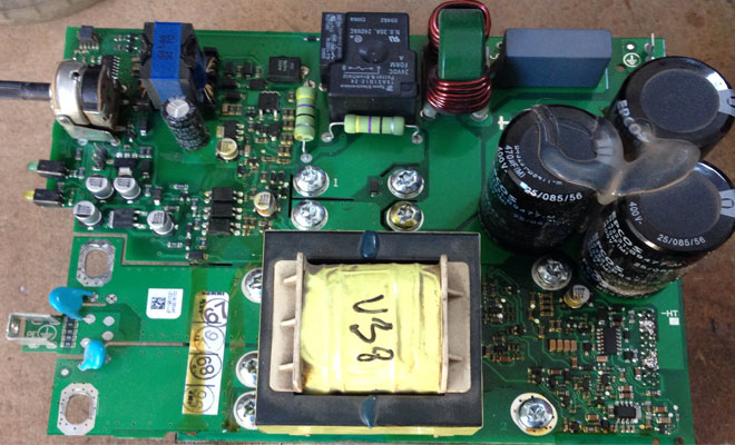
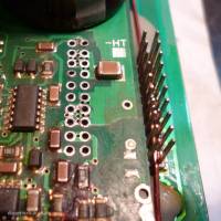
The main reason is the bare junction between the radiator, on which the power elements are located - diodes, transistors (and probably something else) and the control board.
Burnt out PWM - 100 kHz controller.
And the power resistor fell apart (I assume destruction from overheating).
The circuits are found on the global network.
For this device, the circuit completely coincides with the GYSmi 161.
The necessary element was found according to the circuit - it turned out to be an NCP1055 / element and a 47 Ohm resistor. I picked up the resistor in terms of power - in size (I don't know for sure, but it should fit and not affect the work)
The cost of the resistor is 10 rubles. PWM controller 100 rubles.
The repair was done on our own. True, my hands came to the repair only after almost a year () at this time I used another device, however, I continue to use it to this day.
The device passed the test after the repair. He ignites the arc. Keeps it stable. Although I tried to cook without a mask, so for testing.
This problem area was protected with a silicone sealant. In case - it can be deleted, but I think this will not happen.
This problematic place is most likely on all apartments of this brand.
Therefore, you should either constantly blow it with compressed air, or protect the place from the beginning.
Conductive dust adhered to these bare conductors of the problem area - the apparatus was standing next to the grinding machine. I think this is the main reason for the combustion of the PWM and the resistor.
Or their current has increased. or a short circuit on these conductors somehow affected.
| Video (click to play). |
Be careful with such devices
I wish you good luck with your own repairs.
Video Repair of the welding machine GYS Inverter 4000 GYSMI 161 part 1 Reason for the failure of the AEA341 channel
it is one and the same device, only in green color specially for sales within the LeroyMerlinVostok chain of stores.
The main reason is the bare junction between the radiator, on which the power elements are located - diodes, transistors (and probably something else) and the control board.
Burnt out PWM - 100 kHz controller.
And the power resistor fell apart (I assume destruction from overheating).
The circuits are found on the global network.
For this device, the circuit completely coincides with the GYSmi 161.
The necessary element was found according to the circuit - it turned out to be an NCP1055 / element and a 47 Ohm resistor. I picked up the resistor in terms of power - in size (I don't know for sure, but it should fit and not affect the work)
The cost of the resistor is 10 rubles. PWM controller 100 rubles.
The repair was done on our own. True, my hands came to the repair only after almost a year () at this time I used another device, however, I continue to use it to this day.
The device passed the test after the repair. He ignites the arc. Keeps it stable. Although I tried to cook without a mask, so for testing.
This problem area was protected with a silicone sealant. In case - it can be deleted, but I think this will not happen.
This problematic place is most likely on all apartments of this brand.
Therefore, you should either constantly blow it with compressed air, or protect the place from the beginning.
Conductive dust adhered to these bare conductors of the problem area - the device was standing next to the grinding machine. I think this is the main reason for the combustion of the PWM and the resistor.
Or their current has increased.or a short circuit on these conductors somehow affected.
The same device began to beep when plugged into the network and a few seconds after it was turned off, during operation, the squeak is almost inaudible, it cooks perfectly. Is it worth getting into it, or not? And what to look at?
squeak is normal. capacitors are charged. if you remove the plug, there will be no squeak.
says one that it squeaks a little trance because of something there.
Hello. On the Gysmi 161, the diode at the output burned out, replaced all 4 diodes, but now it cooks only at the maximum current and is not regulated. As they advise on the Internet - to catch up before the thermal protection is triggered, after triggering it should be calibrated - it did not help. Have you faced a similar problem? Thank you
no. look at processors. all schematics on the Internet. analogue of gisemi.
O Great Sen-sei, please tell me what are the names of these elements at face value 2a, which you indicated, which burn out? I gave the same welding to one to use it ((I don’t know what he did with it, I cooked everything myself for 2 years, nothing happened. and what they should be at par. Thanks for the early 😉
+ Mitya Nushtai quote from the description under the video: The necessary element was found according to the diagram - it turned out to be an NCP1055 / element and a 47 Ohm resistor. the resistor was set with a capacity of 1 or 3 watts. in radio stores, ask. on the Internet, the wrong thing may come, and it is better to buy in the store because of the speed and advice of sellers. PWM controller burned out. and the resistor burned out. dug up schemes in the network.
How do you get the power section off the main board?
+ rati inter by heating. only I didn’t do it.
My friend, are you sure that one of the burned-out PWM element is the controller? It seems to me that this is a transit. not?
+ andrey lozhkin there is an ncp105x microcircuit, here is a datasheet for a series:
+ Andrey Lozhkin, according to the schematic diagram, is a microcircuit - and not an ordinary transistor. 100 kHz PWM controller. I bought a spare part in two stores: I also asked - one had the same microcircuit, and the other had other legs, but this is definitely a PWM controller. the sellers are knowledgeable, in the diagram this is a PWM controller, it does not have a radiator, there are four pins.
Repair of power modules in these devices requires a special approach. This is due to the “hi-tech” design of the SMI block.
High technologies, along with convenience for users, cause a lot of problems for those who are involved in the repair of such equipment.
It is unlikely that the manufacturer will listen to this opinion and will definitely not simplify the design. Well, let's leave emotions and be puzzled inverters, circuits, repairs.
Interests us GYSMI 145, one of the worthy representatives in a glorious family inverter welding machines.
The complaint about this technological device was extremely simple "turns on but does not cook“.
We immediately call the output connectors - three options are possible:
1. It rings like a diode - everything is fine.
2. Short circuit - one of the diodes of the output bridge is broken
3. Break - one or more racks of the power module are burnt out or broken.
The second option happened in this device, you need disassemble inverter and get to the diodes.
We are interested in the rear of this welder, or rather a radiator with an SMI board, which is soldered into the main board with a 20-pin connector.
To get to the diodes on this module, you need to CAREFULLY unsolder the power unit, and after repair, also CAREFULLY solder it into the board, in no case no wires or additional connectors, only soldering.
On the forums about the repair of welding inverters GYSMI you can find many ways to delicately unsolder this connector. Alternatively, you can use a special nozzle for a 100 watt soldering iron.
Everything is simple, although there is a small BUT. The device is not made from a conventional soldering iron. here is more about it: Glowing soldering iron.
Apply the above gadget to the GYSMI 145 power unit and unsolder the structure.
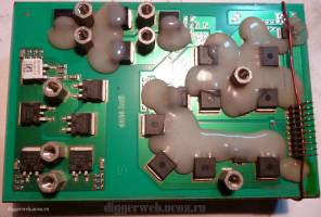
We got access to the diodes, but the difficulties did not end there.
Firstly - you need to find a broken diode, and for this you need to unsolder all the anodes.
Secondly - when we find the broken diode, it must be unsoldered.
Thirdly - solder a new diode.
As you can see, soldering is constantly required, but the massive radiator of this block will not allow the parts to warm up to the melting temperature of the solder. It is necessary to warm up the radiator, and for this you can use one more special device.
It is not advisable to overheat the module, irreversible changes may occur, which is not included in our plans.
A small digression is about overheating.
EVD
Gift from GUS 161
GUS 161 broke down. The reason is out of a number of standard ones. The stand on the power diode bridge fell off and burned out. He warmed up the entire module on a gas stove. Restored.
Cracked the pain less gently. Three tracks were restored by conductors.
Collected. Included. SHOT!
The driver was smashed. A bunch of SMD there too.
I started to figure it out. Before disassembly, the control worked. All diagrams are normal.
Split. One power transistor is killed, current resistors 3pcs. 0.1 Ohm too.
Let me remind you that the power module is filled with a wonderful sealant. Checking the rest of the transistors. Like whole. HOW can this be? I'm starting to peel off the sealant.
Oh Miracle! The elements are removed together with the sealant!
The photo shows the "removed" 15 Ohm resistor from the gate circuit. The shutter itself is raised above the board by a hundred square meters. The rest of the components are the same.
CONCLUSION
When the module heats up to the melting point of the solder, the sealant, upon subsequent cooling, raises the components located under it!
Before taking on the repair of such devices, think about the time spent, nerves and funds. A source
A couple of comments about.
First: most likely, the parts do not come off when the sealant cools, but rather when heated, as soon as the temperature reaches the melting point of the solder, the sealant tears off the parts from the board. It is rubber, and when heated, it tends to swell up, so it tears off the parts, and when it cools, it does not solder them anyway. But this does not change the situation, you need to warm it up carefully, do not overdo it.
Second: warming up on a gas stove is fraught, since it is difficult to monitor the heating temperature. In this case, it is better to take an ordinary electric stove and turn it on through LATR, if you have one at your disposal.
This is a small digression, and now let's get back to our device. We take a new diode and using the same 100 watt soldering iron we solder it into the board. The main thing is that the diode lies flat without distortions and as tightly as possible.
We fasten everything as expected, install it in the case and try to turn it on.
If everything is done correctly and accurately, the device will work. One has only to say that the inverter is designed to operate at currents of 70-90 amperes, this is an electrode of 2-2.5 mm. It is unsafe to use a larger diameter and STTH2003CG diodes should be installed from the same series or selected according to their parameters. If there are no identical ones, it is better to change everything.
Attention!
When repairing welding inverters with your own hands, be careful not to really regret “the time, nerves and money spent”.
Repair of welding inverters GYSMI and other manufacturers.
The manifestation of a malfunction according to the owners: does not work
What preceded the breakdown: unknown, stopped cooking, worked 3, tried to fix it elsewhere
The following problems have been identified at various times: control board malfunction; malfunction of the rectifier circuits of the welding current; malfunction of the power section control circuit; malfunction of the rectifier circuits of the welding current. there is no power outlet. no network cable. preventive cleaning required; malfunction of the control board. power block malfunction
Work performed: repair of the control circuit of the power unit; repair of welding current rectifier circuits, repair of power supply circuits; repair of the control circuit of the power section, repair of the power section of the high-frequency converter
- disassembly. cleaning. ncp replacement, check on the welding table. assembly.
- disassembly. cleaning. replacing the diode on the power board.
- check on the welding table.
- resistors 100 ohm 2 pcs, resistor 47 ohm 1 pc
- working relay
- track recovery
- disassembly. separation of boards. cleaning. replacement of the rectifier diode. power outlet replacement
- installation of a power plug.
- disassembly. cleaning. replacement of defective parts.
- diode replacement.
In this section, practical cases of repair from our service center
Be careful! The information provided should not be taken as a guide to action, since in the event of an attempt to repair complex electronic devices by unqualified personnel, various negative consequences may occur.
Inverter welding machines are gaining more and more popularity among master welders due to their compact size, low weight and reasonable prices. Like any other equipment, these devices can fail due to improper operation or due to design flaws. In some cases, the repair of inverter welding machines can be carried out independently by examining the inverter device, but there are breakdowns that are eliminated only at the service center.
Welding inverters, depending on the models, operate both from a household electrical network (220 V) and from a three-phase (380 V). The only thing to consider when connecting the device to a household network is its power consumption. If it exceeds the capabilities of the wiring, then the unit will not work with a sagging network.
So, the following main modules are included in the device of an inverter welding machine.
Just like diodes, transistors are installed on radiators for better heat dissipation from them. To protect the transistor unit from voltage surges, an RC filter is installed in front of it.
Below is a diagram that clearly shows the principle of operation of the welding inverter.
So, the principle of operation of this module of the welding machine is as follows. The primary rectifier of the inverter is supplied with voltage from the household electrical network or from generators, gasoline or diesel. The incoming current is alternating, but passing through the diode block, becomes permanent... The rectified current is fed to the inverter, where it is converted back to alternating current, but with changed frequency characteristics, that is, it becomes high-frequency. Further, the high-frequency voltage is reduced by a transformer to 60-70 V with a simultaneous increase in the current strength. At the next stage, the current again enters the rectifier, where it is converted to DC, after which it is supplied to the output terminals of the unit. All current conversions controlled by a microprocessor control unit.
Modern inverters, especially those based on the IGBT module, are quite demanding on the rules of operation. This is explained by the fact that when the unit is operating, its internal modules give off a lot of heat... Although both radiators and a fan are used to remove heat from power units and electronic boards, these measures are sometimes not enough, especially in inexpensive units. Therefore, you need to strictly follow the rules that are indicated in the instructions for the device, implying periodic shutdown of the installation for cooling.
This rule is usually referred to as the “Duty Cycle” (Duty Cycle), which is measured as a percentage. Not observing the PV, overheating of the main units of the apparatus occurs and their failure occurs. If this happens with a new unit, then this breakdown is not subject to warranty repair.
Also, if the inverter welding machine is working in dusty rooms, dust settles on its radiators and interferes with normal heat transfer, which inevitably leads to overheating and breakdown of electrical components. If it is impossible to get rid of the presence of dust in the air, it is necessary to open the inverter case more often and clean all the components of the device from accumulated dirt.
But most often inverters fail when they work at low temperatures. Breakdowns occur due to the appearance of condensation on the heated control board, as a result of which a short circuit occurs between the parts of this electronic module.
A distinctive feature of inverters is the presence of an electronic control board, therefore, only a qualified specialist can diagnose and eliminate a malfunction in this unit.... In addition, diode bridges, transistor blocks, transformers and other parts of the electrical circuit of the apparatus can fail. To carry out diagnostics with your own hands, you need to have certain knowledge and skills in working with measuring instruments such as an oscilloscope and a multimeter.
From the above, it becomes clear that, without the necessary skills and knowledge, it is not recommended to start repairing the device, especially electronics. Otherwise, it can be completely disabled, and repairing the welding inverter will cost half the cost of a new unit.
As already mentioned, inverters fail due to external factors affecting the “vital” units of the apparatus. Also, malfunctions of the welding inverter can occur due to improper operation of the equipment or errors in its settings. The most common malfunctions or interruptions in inverter operation are as follows.
Very often, this breakdown is caused by faulty network cable apparatus. Therefore, first you need to remove the cover from the unit and ring each wire of the cable with a tester. But if everything is in order with the cable, then more serious diagnostics of the inverter will be required. Perhaps the problem lies in the standby power source of the device. The repair technique for the “duty room” using the example of a Resant brand inverter is shown in this video.
This malfunction can be caused by an incorrect setting of the amperage for a certain diameter of the electrode.
You should also consider and welding speed... The smaller it is, the lower the current value must be set on the control panel of the unit. In addition, to match the current strength to the diameter of the additive, you can use the table below.
If the welding current is not regulated, the cause may be breakdown of the regulator or violation of the contacts of the wires connected to it. It is necessary to remove the cover of the unit and check the reliability of the connection of the conductors, and, if necessary, ring the regulator with a multimeter. If everything is in order with him, then this breakdown can be caused by a short circuit in the inductor or a malfunction of the secondary transformer, which will need to be checked with a multimeter. If a malfunction is found in these modules, they must be replaced or rewound to a specialist.
Excessive power consumption, even when the device is not loaded, most often causes turn-to-turn closure in one of the transformers. In this case, you will not be able to repair them yourself. It is necessary to take the transformer to the master for rewinding.
This happens if the voltage drops in the network... To get rid of the sticking of the electrode to the parts to be welded, you will need to correctly select and set up the welding mode (according to the instructions for the device). Also, the voltage in the network may sag if the device is connected to an extension cord with a small wire cross-section (less than 2.5 mm 2).
It is not uncommon for a voltage drop that causes the electrode to stick when using a power strip that is too long. In this case, the problem is solved by connecting the inverter to the generator.
If the indicator is on, this indicates overheating of the main modules of the unit. Also, the device can turn off spontaneously, which indicates tripping of thermal protection... So that these interruptions in the operation of the unit do not occur in the future, again, it is necessary to adhere to the correct mode of the duration of the on (DC). For example, if duty cycle = 70%, then the device should work in the following mode: after 7 minutes of operation, the unit will have 3 minutes to cool down.
In fact, there can be a lot of various breakdowns and the reasons that cause them, and it is difficult to list them all. Therefore, it is better to immediately understand what algorithm is used to diagnose the welding inverter in search of faults.You can find out how the device is diagnosed by watching the following training video.
Repair of welding inverters, despite its complexity, in most cases can be done independently. And if you are well versed in the design of such devices and have an idea of what is more likely to fail in them, you can successfully optimize the costs of professional service.
Replacement of radio components in the process of repairing a welding inverter
The main purpose of any inverter is to generate a constant welding current, which is obtained by rectifying a high-frequency alternating current. The use of a high-frequency alternating current, converted by means of a special inverter module from a rectified mains supply, is due to the fact that the strength of such a current can be effectively increased to the required value using a compact transformer. It is this principle underlying the operation of the inverter that allows such equipment to have compact dimensions with high efficiency.
Functional diagram of the welding inverter
The welding inverter circuit, which determines its technical characteristics, includes the following main elements:
- a primary rectifier unit, the basis of which is a diode bridge (the task of such a unit is to rectify an alternating current coming from a standard electrical network);
- an inverter unit, the main element of which is a transistor assembly (it is with the help of this unit that the direct current supplied to its input is converted into an alternating current, the frequency of which is 50–100 kHz);
- a high-frequency step-down transformer, on which, due to a decrease in the input voltage, the output current is significantly increased (due to the principle of high-frequency transformation, a current can be generated at the output of such a device, the strength of which reaches 200–250 A);
- output rectifier, assembled on the basis of power diodes (the task of this block of the inverter includes rectifying an alternating high-frequency current, which is necessary for performing welding).
The welding inverter circuit contains a number of other elements that improve its operation and functionality, but the main ones are the above.

