Details: Apollo 24 compressor DIY repair from a real master for the site my.housecope.com.
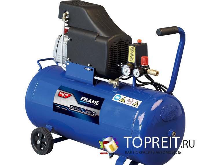
Direct drive oil FIAC APOLLO 24-2 compressor, single stage. Distinctive features of the model:
§ pressure switch provides automatic regulation;
§ there is a thermal sensor to protect the motor from overheating;
§ the safety valve allows you to regulate the pressure, and also guarantees the safety of the equipment;
§ an air filter is built into the compressor head, which cleans the air from external contaminants;
§ housing made of polystyrene, which makes it possible to reduce the noise level and protect against burns;
built-in pressure regulator.
Device and principle of operation
The compressor consists of the following main assembly units and parts shown in fig. P1.
Compressor group 1 - piston type, single-stage, single-cylinder air-cooled. Designed to produce compressed air. The motors of the compressor groups are equipped with a thermal protection installed inside the winding, which stops the compressor when the temperature reaches too high values. The compressor automatically switches back on after 15–20 minutes.
Receiver 8 is designed to accumulate compressed air and has a connection for installing a pressure switch - 4, a check valve - 12, a drain valve - 10.
The pressure switch 4 is used to ensure the operation of the compressor in automatic mode, to maintain the pressure in the receiver within the specified limits.
Reducer 5 is designed to reduce the outlet air pressure in the range from 0 to 8 atm.
The unloading air duct 13 serves to discharge compressed air from the discharge air duct 14 after stopping the compressor in order to facilitate its subsequent start-up.
| Video (click to play). |
The outlet valve 6 is designed to supply air to the consumer.
Safety valve 3 serves to limit the maximum pressure in the receiver.
The check valve - 12 provides the supply of compressed air only in the direction from the compressor unit to the receiver.
Drain valve -10 serves to drain condensate from the receiver.
Air filter - 2 serves to protect the piston group from dust and foreign particles.
Filling of oil into the crankcase is done through a hole in the cover of the cylinder block (in the transport state, closed with a plug, and in operating mode with a dipstick-15), the oil is drained through a hole in the bottom of the crankcase, closed with a plug.
Manometer - 7 is designed to control the pressure in the receiver.
Do not unscrew the air connections while the receiver is under pressure.
Do not carry out any operations on the compressor if the plug is not disconnected from the mains.
You should not make any attempts to eliminate the faults that have arisen on your own. In such cases, contact the service centers at the addresses indicated in the warranty coupons.
Never use the compressor in a damp room or in the immediate vicinity of water. Strictly follow the rules of personal safety.
Do not use the compressor in the presence of flammable liquids and gases.
Do not place flammable objects near the compressor.
During interruptions in operation, the pressure switch must be in the off position. (0).
Never aim the air jet at people or animals. People and animals must be kept out of the compressor's operating range.
Table A2. FIAC Apollo Compressor Specifications
There are situations when the air compressor, peacefully rattling the engine in the corner of the garage, starts to malfunction, or even turns off altogether. And at this moment, as luck would have it, there is a need for it.Do not be afraid, after studying theoretical information, repairing a compressor with your own hands will not seem like something unattainable.
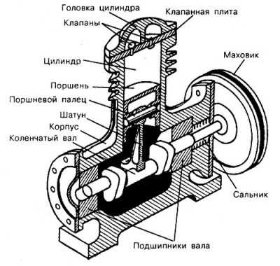
Compressors with a piston system electric motor have found the greatest application in car repair shops. In the supercharger crankcase, the transfer rod moves along the axis back and forth, giving the oscillatory moment to the reciprocating movement of the piston with O-rings. The bypass valve system located in the cylinder head works in such a way that when the piston moves downward, air is taken from the inlet pipe, and upward - it is returned to the outlet.
The gas flow is directed to the receiver, where it is compacted. Due to its design, the blower produces an uneven air stream. Which is not applicable to spray gun use. A kind of condenser (receiver) saves the situation, which smooths out the pressure pulsations, giving out a uniform flow at the outlet.
A more complex design of the compressor unit implies the attachment of additional equipment designed to provide automatic operation, dehumidification and humidification. And if in the case of a simple execution it is easy to localize a malfunction, then the complication of the equipment execution complicates the search. The following are the most common faults and remedies for the most common piston-type compressed gas systems.
To make it easier to find the problem, all defects can be classified by the nature of the malfunction:
- Compressor unit blower does not start
- Compressor motor hums but does not pump air or fills air reservoir too slowly
- At start-up, the thermal protection circuit breaker is triggered or the mains fuse is blown out.
- When the blower is turned off, the pressure in the compressed air tank drops
- Thermal protection circuit breaker periodically trips
- Exhaust air contains a lot of moisture
- Engine vibrates violently
- Compressor runs intermittently
- Air flow is consumed below normal
Let's consider all the causes of the problems and how to fix them.
Failed ones are replaced by passive protection devices of the same rating as defective ones. In no case are hot-melt inserts designed for a higher electric current allowed. If the fuse blows again, you should find out the cause of the failure - probably a short circuit at the input of the circuit.
The second reason why the unit does not start is that the pressure control relay in the receiver is faulty or the level settings are out of order. To check, gas is released from the cylinder and the supercharger is tested. If the engine is running, the relay is reset. Otherwise, the defective part is replaced.
Also, the engine will not start when the thermal overload circuit breaker is triggered. This device turns off the power supply circuit of the winding of the electrical device in case of overheating of the piston system, fraught with seizure of the motor.Let the blower cool down for at least 15 minutes. After this time has elapsed, restart it.
With an underestimated mains voltage, the electric motor does not master the scrolling of the axis, while it will hum. With this malfunction, first of all, we check the voltage level in the network using a multimeter (it must be at least 220 V).
If the voltage is normal, then the pressure in the receiver is probably too high, and the piston does not overpower the pushing of air. In this case, manufacturers recommend setting the “AUTO-OFF” automatic switch to the “OFF” position for 15 seconds and then moving it to the “AUTO” position. If this does not help, then the pressure control switch in the receiver is faulty or the bypass (check) valve is clogged.
You can try to eliminate the last drawback by removing the cylinder head and cleaning the channels. Replace the defective relay or send it to a specialized center for repair.
Compressor start-up is accompanied by blown fuse or activation of automatic thermal protection
This malfunction occurs if the installed fuse is below the recommended rated power or the supply network is overloaded. In the first case, we check the compliance of the permissible currents, in the second, we disconnect part of the consumers from the electric main.
A more serious cause of the malfunction is incorrect operation of the voltage relay or breakdown of the bypass valve. We bypass the relay contacts according to the scheme, if the engine is running, then the actuator is faulty. In this case, it is more advisable to contact an official service center for technical support or replace the relay yourself.
A drop in compressed air pressure indicates that there is a leak somewhere in the system. Risk areas are: high pressure air line, piston head check valve or receiver outlet cock. We check the entire pipeline with a soapy solution for air leaks. We wrap the detected defects with sealing tape.
The drain cock may leak if not properly closed or defective. If it is closed all the way, and the soapy solution is bubbling on the spout, then we change this part. When screwing in a new one, do not forget to wind up the fum tape on the thread.
In the case of tightness of the air line and the exhaust valve, we conclude that the compressor control valve is not working correctly. For further work, be sure to bleed all the compressed air from the receiver! Next, we continue to repair the compressor with our own hands, disassembling the cylinder head.
If there is dirt or mechanical damage to the bypass valve, we clean it and try to fix the defects. If the malfunction is not eliminated, then we replace the control valve.
This defect occurs when the power supply voltage is too low, the air flow is poor, or the room temperature is too high. We measure the voltage in the network using a multimeter; it must be at least the lower limit of the range recommended by the manufacturer.
Poor air flow into the discharge system is due to a clogged inlet filter. The filter should be replaced or washed according to the unit's maintenance manual. The piston engine is air-cooled and often overheats when in a poorly ventilated area. The problem is solved by moving the compressor unit to a room with good ventilation.
This situation occurs under the following conditions:
- Large accumulation of moisture in the receiver
- Air intake filter dirty
- The humidity in the room of the compressor unit is increased
Moisture in the output stream of compressed air is fought by the following methods:
- Drain excess fluid from the cylinder regularly
- Clean or replace the filter element
- Move the compressor unit to a room with drier air or install additional filter-moisture separators
In general, piston engines are prone to high vibration. But, if the previously relatively quiet compressor unit begins to rumble, there is a high probability that the engine mounting screws are loosened or the material of the vibration cushions is worn out. This malfunction is eliminated by pulling all fasteners in a circle and replacing the polymer vibration isolators.
Interruptions in the operation of the engine can be caused by incorrect operation of the pressure control switch or too intensive extraction of compressed air.
Excessive gas consumption occurs due to a discrepancy between the compressor capacity and the power consumption. Therefore, before buying a new pneumatic tool, carefully study its characteristics and air consumption per unit of time.
Consumers should not take more than 70% of the compressor capacity. If the power of the blower with a margin overlaps the requests of the pneumatic tools, then the pressure switch is faulty. We either repair it or replace it with a new one.
This malfunction occurs as a result of a gas leak in the high pressure system or a clogged air intake filter. Air leakage can be minimized by pulling all butt joints and wrapping them with sealing tape.
Sometimes it happens that when draining condensate from the receiver, they forget to completely close the drain valve, which also leads to a gas leak. This problem is easy to solve - by tightly closing the valve. If the dust filter is clogged, clean it or, even better, replace it with a new one.
Most of the above malfunctions can be avoided by correctly carrying out the first start-up and running-in of the mechanisms, as well as performing regular routine maintenance.
In order for the device to function properly for a long time, the recommended maintenance should be started at the initial stages of operation. Experts recommend the following actions from the date of purchase:
Timely observance of these simple requirements will keep the mechanism in good condition. Such a time-consuming procedure as repairing a compressor with your own hands will be required extremely rarely. Proper grounding will avoid problems with the electrical part of the device. Regular replacement of oil and cleaning filters will prevent premature wear of rubbing parts.
The main purpose of an air compressor is gas compression and continuous supply of a jet of air under pressure to pneumatic equipment and pneumatic tools. Such air is an energy carrier and ensures the operation of spray guns, airbrushes, wrenches, and a tire inflation gun.
The listed pneumatic tool is safer to work with than a power tool, for example. The pneumatic equipment cannot have a short circuit that can lead to electric shock and fire. That is why such a tool is widely used in car repair shops or when repairing a car with your own hands.
The air compressor is applicable to households and when it stops working, it needs to be repaired. However, the repair of compressors is not particularly difficult, it is quite possible to do it yourself.
To understand the problems of a compressor, you need to clearly understand what elements it consists of and what they are intended for. The compressor, in the minimum configuration, consists of a blower (an engine that creates an air flow) and a receiver - a container that contains compressed air. Reciprocating compressors are most commonly used.
One of the main requirements for a compressor is its safety. If the pressure in the receiver is not controlled, the compressor will burn out. There is a high probability that the receiver cylinder may explode. To prevent this, the receiver is equipped with an electronic relay that automatically turns off the compressor when the air pressure reaches a certain value.
The air compressor is equipped with a pressure gauge that indicates the amount of air pressure in the cylinder. A check valve is used to protect the compressor from negative influences. Its main function is to prevent air from returning back to the compressor when the unit is turned off or otherwise interfered with.
More complex compressor designs are characterized by additional equipment such as compressor automation. Usually in small compressors, the automation unit maintains a pressure of up to eight atmospheres using a pressure switch, turning on or off the power to the electric motor when the minimum or maximum pressure in the receiver is reached.
In this case, there are two pressure gauges: the large one shows the pressure in the tank of the receiver, the small one - at the outlet. The pressure switch can be equipped with an unloading valve. When the unit is stopped, it will open, making it easier to start the engine later.
In some models, a cooling radiator is provided on the pipes for supplying air from the compressor to the receiver.
Cooling the air results in less condensation in the receiver. Such a trifle in the design extends the service life of the automation.
The presence of a drain valve allows you to quickly drain condensate from the receiver, because it is advisable to end each operation of the unit with this operation.
The safety valve releases the increased pressure in the receiver if, for some reason, the automation does not work, which protects the compressor motor from overloads.
The air filter protects the piston system from sand, dirt, paint fumes.
The following types of compressors are distinguished:
- Volumetric action - keep gas or air in a confined space, increase pressure. Among them are:
- rotary, principle of operation - suction and compression of gas during rotation of the plates; the working volume decreases, this leads to an increase in pressure.
- piston - pressure is created by the movement of pistons and valves; reliable in operation, but noisier than rotary ones.
- Dynamic - provide compression by increasing the speed of gas movement, increasing its kinetic energy, which is converted into compression energy. Distinguish:
- centrifugal - used for air exchange in mines;
- axial or axial.
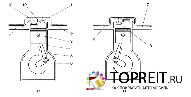
Consider how a piston-type compressor works, air or gas in it is compressed by a piston that moves through the cylinder:
- When the piston (3) moves up the compressor cylinder (4), the working gas is compressed. The electric motor moves the piston through the crankshaft (6) and connecting rod (5).
- The suction and discharge valves are opened and closed by gas pressure.
- The diagram on the left shows the gas suction phase into the compressor. When the piston moves down, a vacuum is created in the compressor and the inlet valve (12) opens. Thus, the gas enters the compressor space.
- The right diagram shows the gas compression phase. The piston moves upwards and the outlet valve (1) opens. The gas leaves the compressor at high pressure.
The blower itself produces an uneven air stream, which cannot be used, for example, for using a spray gun. The receiver saves the day by smoothing out the pressure pulsations.
Having replenished the stock of information about the compressor unit, you can repair the compressor yourself. A distinction is made between the following compressor system malfunctions:
- The compressor unit blower does not start.
- From time to time, the thermal cut-out is triggered.
- When the compressor starts, the thermal cut-out is triggered and the fuse is blown out.
- The engine of the unit runs, but does not pump air into the receiver, or does it slowly.
- When the supercharger is turned off, the pressure in the receiver drops.
- High moisture content in the air outlet.
- Strong vibration from the engine.
- The compressor unit works intermittently.
- The air flow is consumed below the norm.
There are several probable reasons why the compressor will not start..
If the unit does not start and does not hum, check the supply voltage with an indicator screwdriver. If there is a phase, the connections of the plug to the socket are normal, it is worth checking the fuses that are subject to melting.
Defective fuses are replaced with others of the same rating. New fuses with higher current ratings must not be installed. If the fuses blow repeatedly, there may be a short circuit at the input to the circuit.

