In detail: KPP KAMAZ do-it-yourself repair from a real master for the site my.housecope.com.
A gearbox (gearbox) is a necessary device for any car. With its help, changes are made in the motor torque and the subsequent transfer of this moment to the working axles. A gearbox with a divider on KAMAZ vehicles contributes to a fairly wide range of adjustments of both traction and speed characteristics, thereby using the power unit of the vehicle with the greatest efficiency.
The gearbox device, which is used on KAMAZ models, does not differ significantly from analogs used by other tractor manufacturers. However, it has some design features.
The most common gearbox designs installed on KAMAZ trucks are called model 14 and model 15. They are designed according to the following principle. Several shafts are mounted in the crankcase at once: intermediate, driven and driving. All of them are equipped with gears and synchronizers. Only the gears of the transmission are installed as a separate block, which is responsible for moving backwards. In addition, the upper part of the box is equipped with a separate block, which houses the mechanism for changing the speeds.
In order for the car's gearbox to serve as long as possible, it is necessary to periodically maintain this device. These simple measures consist in adjusting the gearshift drive, the size of the gap in the divider activation valve, as well as in the periodic renewal of the oil.
The oil change in the KAMAZ gearbox with a divider must be carried out at least once a year. This is provided that the car must not travel more than ninety thousand kilometers between two replacements. In models that are involved in the construction of large facilities, for the transportation of cargo in quarries or work in other difficult conditions, the oil will have to be changed several times more often. Thus, the duration of the oil working period may differ from the one recommended by the manufacturer. It directly depends on the conditions in which the car is operated, as well as on the model of the box installed on the car.
| Video (click to play). |
You can check how the oil level in the box corresponds to the recommended parameters using a special indicator, which is located on the filler cap. This option is used to check models 14 and 15. Gearboxes with index 161 and ZF, you can check the oil level using the check holes located on the box body.
The oil must be changed when the engine is warmed up to operating temperature, since at this moment the oil has a low viscosity. Waste oil can be removed through special drain holes located at the bottom of the box. In model 161, you will have to unscrew the oil filter additionally.
The most frequent breakdown of KAMAZ gearboxes is wear of parts. This problem can be solved only by replacing the old structural element.
Sometimes problems arise, for example, automatic shutdown of the transmission or difficulties in turning it on, the reason for which lies in the violation of the adjustments of the mechanisms and units of the box. In this case, you just need to return the technical value of the adjustments to its original position and the problem will be solved.
Why and how often you need to flush the car's cooling system, as well as what are the best cleaners to use, see here. What kind of oil should be poured into the engine and what you need to pay attention to when choosing, read here.
To make repairs, you need to know well how the structure works, or there should be a KAMAZ gearbox diagram with a divider at hand. The gear divider itself is a mechanical gearbox, the main task of which is to increase the gear ratios of the main gearbox. The divider design consists of the following components:
- two gears;
- blocking synchronizing rings on both sides;
- synchronizing clutch with teeth;
- two types of shafts;
- device body;
- a fork designed for gear shifting, as well as a lever for these purposes and a fork shaft.
The list of repair work of the gearbox divider consists of disassembling the structure of the device, then there is the process of troubleshooting and replacement of worn out elements, then the process of assembly and testing.
The divider structure is disassembled according to the following algorithm:
After the defects of the structural parts are identified, it is necessary either to eliminate them, or replace the worn-out parts with new ones. In order not to later resort to monthly repair of the box, it is best to use only original spare parts from the manufacturer. Fortunately, purchasing parts for a gearbox divider for a brand of a domestic car is not such a big problem. And the build quality of "native" spare parts is always higher than that of Chinese counterparts.
The divider is assembled in reverse order.
The last, but not insignificant, stage of the repair consists in checking the serviceability of all parts and mechanisms of the device after assembly. It is also worth paying attention to checking the complex work of the divider itself, in which malfunctions appear not only during its operation, but also after repair.
REPAIR OF TRANSMISSION OF KAMAZ VEHICLES - PART 1
To check the divider reducing valve, remove the valve from the gearbox and install it on the bench, which must be equipped with a pneumatic system with an air pressure of 588.686 kPa (6. 7 kgf / cm2), which is supplied to the valve inlet. At the outlet of the valve, a pressure gauge must be installed to control the pressure, providing a measurement accuracy of at least 4.9 kPa (0.05 kgf / cm2). Check the outlet air pressure, which should be 387.436 kPa (3.95.4.45 kgf / cm2). 11if the pressure does not correspond to the specified value, remove the seal, unscrew the plug 12 (Fig. 143) and, selecting the required number of washers 13, adjust the valve and seal.
Rice. 143. Reducing valve: 1 - spring housing; 2 - inlet valve spring; 3 - gasket; 4 - inlet valve; 5 - inlet valve stem; 6 - case; 7 - union nut; 8 - membrane; 9 - washer; 10 - housing cover; 11 - balancing spring; 12 - cork; 13 - adjusting washer
For removing and disassembling the divider control valve
when repairing, unscrew the fastening bolts of the three air ducts, disconnect the divider control valve 1 (see Fig. 138) from the support bracket 2, unscrew the screws securing the cable clamp to the gear shift lever, remove the rubber grommet from the sunroof seal support housing, unscrew the screws securing the valve switch cover control, carefully remove the cover with clips and a spring, paying attention to the safety of the balls, and disconnect the cable from the switch lever. Remove the divider control valve assembly and disassemble it.
In case of partial disassembly: unscrew bolts 2 (Fig. 144) fastening the cover 3 with a cable to the valve body 5, wash the valve parts and lubricate the working surfaces of the parts with grease 158. Assemble the control valve. Lubricate the cable by pouring it into the cable sheath using an oiler 10. 15 g of TSp-15K oil. If the cable breaks, completely disassemble the crane and replace the cable, to do this, disconnect the valve cable with the cover 3 assembly, unscrew the union nut 6 and pull the cable with the spool assembly out of the cable sheath, then unscrew the lock nut 1 (Fig. 145), unscrew the tip 3 of the cable from spool 6.Make a new rope from a multi-core screw rope (steel 65GA GOST 3062-80) with a diameter of 1.6 mm according to the dimensions shown in Fig. 130, insert a new cable into the spool, screw in the cable end, ensuring the axial movement of the cable relative to the spool 0.1. 0.3 mm and securely lock with nut 1. After assembly, the valve spool 6 should rotate freely relative to the cable by hand. Assemble the control valve.
When checking the pneumatic system for leaks, determine the location of the air leak by ear. By alternately moving the control switch to the HIGH GEAR or LOW GEAR position, listen to the air ducts of the pneumatic divider control system, and pressing the clutch pedal
until it stops, - air ducts of the divider switching system.
Repair the detected leak by tightening the bolts or replacing the sealing washers and defective air lines.
Adjust the engagement of the gear divider synchronizer clutches with compressed air supplied to the pneumatic system and the divider activation valve pressed all the way down as follows:
- remove the seals, unlock and unscrew the two set screws 1 and 5 (Fig. 146) on the body of the gear change mechanism of the divider and remove the cover 3 of the inspection hatch;
- move the spool of the divider control valve to the LOW GEAR position and, screwing in the rear set screw 5 until it touches the lever, turn it another 1/4 turn and lock it with a lock nut 4. In this position, the drive shaft (with the gearbox removed) must turn by hand easy, without jamming;
- move the spool of the splitter control valve to the HIGHER GEAR position and adjust the engagement with the front set screw 1 as indicated above;
- through the inspection hatch in the body of the gear change mechanism of the divider, check the operating stroke of the lever until it stops against the set screws (16.5. 19 mm in the center of the hole in the lever);
- lock the set screws 1 and 5 and seal.
When repairing the remote control gear drive, to reduce the effort when shifting gears, replace the grease in the three drive bearings and the ball heads of the pivot joints of the levers. Pump fresh grease into the bearings through
grease fittings by screwing them instead of plugs in the support housings.
If, after lubricating the bearings, the force on the lever during gear shifting has not changed or has decreased insufficiently, disassemble the bearings in the following order:
- unscrew the bolts 19 (see Fig. 138) fastening the adjusting flange; unscrew the mounting bolts of the support on the clutch housing;
- remove the rubber cover of the swivel joint, paying attention to the safety of the restraining ball and spring;
- unscrew the adjusting flange 18 from the intermediate rod and pull the intermediate rod out of the support;
- disconnect the head 6 of the front linkage, paying attention to the safety of the ball and the spring;
- Disconnect the covers 15 from the support located in the flywheel housing;
- remove the front link located in the camber of the cylinder block;
- remove the gear lever support located at the front end of the block as described below. Remove the crackers 11, bushings 18, spring 14 from the support bodies.
Flush the parts and cavities of the supports with kerosene or diesel fuel, replace worn O-rings. When assembling, lubricate the rubbing surfaces with grease 158; put fresh grease in the cavity of the supports. Adjust the remote actuator after assembly.
To regulate the remote control of the gearshift mechanism for models 14 and 15:
- set the gear shift lever to neutral position;
- loosen the clamping bolts 24 (see Fig. 138) of the clamping adjusting flange 18, unscrew the four connecting bolts 19 and screw the adjusting flange one or two turns onto the intermediate rod 17;
- unscrew the locknuts 8 and 22 of the set screws 9 and 21.Lock the lever 7 of the tip and the lever of the rod 23 by screwing the set screws into the holes of the levers;
- unscrewing the adjusting flange until its end comes into contact with the end of the rod flange over the entire plane, connect them with four bolts 19. Fasten the flange to the intermediate rod by tightening the bolts 24;
- unscrew the set screw 9, located on the front support of the gear lever, by 31 mm, and the set screw 21, located on the rear support of the lever, by 16 mm. Then secure them with locknuts.
To remove and disassemble the gear lever support, tilt the cab, remove the noise-insulating cover of the gear lever, the support seal parts, disconnect the air ducts of the pneumatic system of the divider (model 15 gearboxes), the generator mounting bracket, the rods and the fuel pump control cables, remove the head 6 (see. fig. 138) of the front link, unscrew the bolts securing the support bracket to the engine and remove the support, disconnect the valve 1 of the divider control and the gear change lever.
Disassemble the support in the following sequence: remove the rubber boot 14 (see Fig. 139), the holder 9 of the cap, the brake spring, the pressure disc 6, the disc 8 of the brake, unscrew the nut 15, remove the spring 10 and the pressure washer 11, remove the lever 4 of the tip, remove pins 16 and axle 12 of the lever tip.
Wash the parts, lubricate the rubbing surfaces with grease 158. When assembling, screwing the nut 15, align its groove with the bracket groove and open it out. Fill the cavity A of the support with grease 158. The tip 13 of the lever should rotate in mutually perpendicular directions with a force of 24, 5. 34, 3 N (2.5. 3.5 kgf) applied to the tapered surface of the lever tip.
To adjust the gaps between the divider synchronizer carriage and the splitters of the gear divider shift fork, remove the cover 6 (see Fig. 137) of the divider housing inspection hatch. Uncontroll and
unscrew the two bolts securing the fork of the gearshift mechanism in the divider so that the roller 13 with the lever 16 attached to it moves freely in the axial direction, remove the divider switching mechanism.
Rice. 147. Device for centering the drive shaft of the gear divider: 1 - device body; 2 - mounting plate; 3 - locating pin; 4 - adjusting screw; 5 - bolt; 6 - bushing; 7, 13 - springs; 8 - glass; 9 - centering cone; 10 - leading divider shaft: 11 - clamping lever; 12 - persistent washer; 14 - pin; 15 - clamping washer
Center the divider drive shaft 2 with a special tool, which consists of a housing with a centering device and two clamping levers. To do this, insert the centering cone 9 (Fig. 147) into the inner cone of the divider drive shaft, fixing the device to the divider housing by turning the clamping levers 11. The locating pins 3 will center the device relative to surface B, ensuring that the shaft axis is displaced no more than 0.2 mm.
Move the fork 14 (see Fig. 137) to the right until the crack 15 stops in the synchronizer carriage 7. Moving the roller 18 with the lever 16 attached to it to the right, provide a gap of 0.3. 0.6 mm, for which between the mating plane of the divider housing under the gearshift mechanism housing and the head of the lever 16, place a setting plate 2 (see Fig. 147) with a thickness of 0.3. 0.5 mm. Slide the roller up to the stop of the lever head on the plate. Screw in and lock the fork mounting bolts with bend washers. Reinstall the gear divider switch mechanism and inspection cover 6 (see Fig. 137).
To disassemble the gearbox:
- Disconnect divider 4 (see Fig. 136) or clutch housing 38 (see Fig. 128) from the gearbox;
- disassemble the main gearbox in the following order: unscrew the bolts securing the upper gearbox cover 18 and, screwing two bolts into the special threaded holes in the cover (after having unscrewed the plugs from them),remove it; unscrew the nut 26 securing the propeller shaft flange and remove the flange 27, remove the front and rear bearing caps of the driving shaft 1, driven shaft 35 and intermediate shaft 33, screwing the mounting bolts into the special holes in the covers (when removing the covers, pay attention to the safety of the gaskets); remove the retaining ring 21 of the bearing: unlock and unscrew the two bolts securing the thrust washer 31 of the rear bearing of the intermediate shaft; with pullers I801.30.000 remove the rear bearing 22 of the driven shaft, for this use the grip I801.30.100 (fig. 148). Install the grip 8 on the bearing groove and tighten with nuts 1. Turning the screw 4 into the cross-beam 6 and resting the tip 3 against the shaft end, remove the bearing.
Remove the cup 28 (see Fig. 128) of the rear bearing together with the bearing 30 of the intermediate shaft. To remove the intermediate shaft bearing, resting against the stop 3 (Fig. 149) against the crankcase wall
gearbox, screw in two bolts 7 into the threaded hole of the bearing cup until it stops. Resting the tip 4 against the end of the shaft, screw the screw 6 into plate 5 until the bearing with the cup is completely removed.
When removing the countershaft rear bearing cup from the gearbox housing, install a technological thrust washer between the 2nd gear rim of the countershaft and the reverse gear block rim (to avoid breakage of the 2nd gear rim teeth). Remove the drive 1 (see Fig. 128), driven 35 and intermediate 33 gearbox shafts. Using a puller I801.32.000, press axle 12 of the reverse gear block. To do this, set the handle 2 (Fig. 150) to the extreme right position, use the key to screw the screw 1 into the axle of the gear block; then screw the handle 2 on the screw 1 until the axle of the gear block is completely removed.
Take out a block of 14 gears (see Fig. 128), bearings 15 with a lantern ring and thrust washers 13.
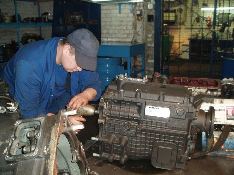
In this article, I would like to share the experience of repairing a KAMAZ vehicle gearbox, namely a model 152 gearbox. This gearbox model is practical and quite hardy, but during operation due to violations associated with its maintenance, it fails. The first thing you have to deal with during repairs is the lack of the required level of transmission oil in the crankcase, instead of the prescribed 12 liters, you can hardly find 3 liters of oil. And there is no need to talk about the fact that this oil was changed in due time. Some find nigrol somewhere, and if you add to it the quality of the spare parts sold, you don't have to think about the cause of the breakdowns for a long time. All this leads to the destruction of bearings, fragments and rollers of which fall between the teeth of the gears, break them, or in the absence of a properly working clutch, the gears themselves are destroyed.
You have decided to repair the checkpoint without resorting to the services of a repair plant. If the breakdown of the gearbox did not entail mechanical damage to the housing or the wear of the bearing seats does not exceed the standard value, then the bearings of the synchronizers and gears can be replaced independently, in a normal workshop. It is not very difficult and does not require the use of special technologies. The only thing I want to warn you against replacing the countershaft gears. The gears are seated and in order to dismantle them, it is necessary to use a hydraulic press and appropriate devices, in their absence, this may either not give any results or lead to injury.
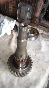
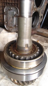
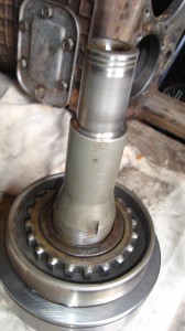
We disassemble the gearbox, first of all, remove the gearbox cover, then remove the input shaft. To do this, it is necessary to remove the cover of the rear bearing of the input shaft and knock out the bearing, the shaft with it comes out of the gearbox housing, when removing the cover, be careful, with fastening bolt stoppers, as a rule, it is difficult to find them in spare parts stores. Having removed the input shaft, we need to unscrew the coupling nut, keep in mind that it has a left-hand thread, by unscrewing the nut, remove the washer and the synchronizer clamping ring, then remove the bearing and change it to a new one.
We remove the secondary shaft in failure, for this it is necessary to remove the bearing cover of the secondary shaft, and through the technological holes of the gear of the first gear, knock out the rear bearing of the secondary shaft, the task is not very simple, be careful not to damage the gear and the gearbox housing.Having removed the bearing, we can remove the output shaft assembly from the housing. The most convenient way to do this is with a non-rigid wire, one end of which must be fixed to the first gear gear by pushing it through the technological hole, the other end is fixed to the synchronizer ring. The shaft is heavy, it is best to take it out together, since it is necessary to direct the gear of the first gear so that it does not cling to the gearbox housing.
Having removed the secondary shaft, we have the ability to replace the gears: first gear, reverse gear, second gear and the synchronizer for second-third gears. In order to replace the gear wheel of the third gear, the gear wheel of the fourth gear and the synchronizer of the fourth - fifth gears, it is necessary to remove the support roller bearing, for which we remove the retaining ring, it is most convenient to remove the bearing using a puller.
We remove the block of reverse gears, for this we unscrew the locking bolt of the stopper and remove the stopper, then from the inside of the gearbox we knock the shaft out and take out the block of gears.
To remove the intermediate shaft, it is necessary to unscrew the cover of the spherical roller bearing, loosen the bolts securing the support washer, loosen the bolts and remove the washer. The spherical bearing is located in the glass; it is most convenient to remove it from the housing together with the glass. Then the shaft can be easily removed.
We have completely disassembled the checkpoint, now you can make defect detection of parts and, if necessary, replace them with new ones. What you need to pay attention to:
-all spline joints should not have visible wear and tear
- it is advisable to replace the roller bearings of the gears, having carefully examined the places of their rolling, whether there is any wear or places pressed by the rollers
- it is also advisable to replace the bearings of the shafts, since, due to the breakdown and the ingress of metal shavings and fragments into the oil, the rolling points of the bearings are likely to be damaged, which will subsequently lead to a repeated breakdown of the gearbox.
- Carefully inspect all the gears for chips, shells, unacceptable contact spots and wear of the gear teeth, I want to repeat, it is not advisable to change the countershaft gears yourself, you most likely will not succeed, at best you will ruin the shaft at worst you will injure yourself.
- tapered synchromesh clips should not be set on fire and worn out, the guide shafts should not dangle and there should be no signs of wear or chips on the splines.
Assembling the checkpoint is necessary in the reverse order. We place the intermediate shaft in the gearbox housing, install the front roller bearings and the rear spherical bearings with a glass. We fasten the support washer, lock it and close the rear cover of the spherical bearing fastening, after installing the gaskets. The shaft should rotate easily by inertia, while there should not be even the slightest jamming and biting of the shaft.
If the intermediate shaft rotates easily and freely, proceed to installing the reverse gear block. We install the axial displacement washers so that the stoppers in them fall into the grooves of the gearbox housing, guide the gear block along the shaft and insert the shaft, lock it with a locking plate.
We collect the input shaft. We put the bearing on the shaft, paying attention to the groove of the retaining ring in the bearing, it should be located from the gearbox housing. We put on the clip. We put on the washer. We tighten the nut. The shaft is now ready for installation.
We collect the secondary shaft. First of all, we install the gear wheel of the third gear, having previously installed the roller bearing, then we install the gear wheel of the fourth gear assembled with a glass and set rollers.
We install a stopper with a spring in a special groove on the shaft and a support washer. We turn the washer along the groove in the splines of the shaft, having previously sunk the stopper until the stopper clicks.Here, pay attention to the fact that the stopper is not jammed, it is freely squeezed out and returned by the spring back, becoming in its seat. If the stopper moves tightly, this can lead to the fact that it will be able to release the support washer, and it will turn along the splines and the gear wheel of the fourth gear will begin to move freely along the splines, which will lead to the rollers falling out, and therefore, the gearbox will fail. synchronizer of the fourth fifth gear. Pay attention to the fact that on different sides it has different spline diameters, put its spline parts correctly, according to the splines of the mating parts. Install the support roller bearing so that its support washer is pressed against the spline part of the shaft, and then install the circlip ...
On the other part of the shaft, we install the second-third gear synchronizer, pay attention to the fact that the protruding part of its splines is directed towards the input shaft. Install the roller bearing and the second gear gear, making sure that the bevel part of the gear is directed towards the synchronizer ...
We install the glass and the roller bearing of the reverse gear, while the holes of the oil channel on the shaft and the glass must match, we install the clutch and the glass with the roller bearing of the first gear gear, install the first gear. Install the support washer.
The output shaft assembly is placed in the gearbox housing. We install the rear bearing of the output shaft into the gearbox housing. We put the input shaft assembly.
Now our task is to install the covers of the rear bearing of the input shaft and the rear bearing of the secondary shaft, they must tightly press the bearings against the gearbox housing so that the bearings cannot rotate in the housing. For this we use shims. When choosing shims, we take into account the thickness of the cover gaskets so that pressing the bearing, the cover is tightly pressed against the gearbox housing.
After installing the rear cover, install the propeller shaft mounting flange and tighten the nut.
Before installing the upper gearbox cover, we check: whether the gear shift forks are dangling on the shafts, and in what condition the crackers are, it is better not to touch them without the need, in the store you will usually buy homemade products of incomprehensible quality. And in general, spare parts in unscrupulous stores are designed for the level of a KAMAZ operator who repairs his car himself, and cannot independently judge the quality of a spare part, and therefore marriage flourishes.
As you can see, we did not encounter anything complicated when assembling the checkpoint, attention and accuracy are more important here, check each step for yourself, the rush will result in a malfunction.
And do not skimp on good transmission oil, the fact that the KAMAZ gearbox should work on nigrol is an old-fashioned delusion.
The gearbox is a very important part of any car, including KAMAZ. Like other techniques, this element is not ideal and periodically fails. There are several of the most common reasons a box breaks. In such cases, it is important to make timely and high-quality repairs to the KAMAZ gearbox.
Sometimes the beginning of the work of the gears in the gearbox divider can begin to occur with some kind of grinding and banging. This becomes possible due to the excessively high pressure level in the system that controls the divider. Also, this problem periodically arises due to wear of the tapered rings, ruptures in the pressure reducing valve. Then the repair of the box requires replacing the synchronizer or the membrane. It is also very important to carefully adjust the pressure relief valve.
Another popular problem with this car's gearbox can be self-shifting on the move. The reasons for this breakdown include some problems in the locking mechanism for switching.Also, some of the gearbox components involved in shifting the adjustment lever may wear out. Such a problem can occur due to a broken lock in the spline of the driven shaft. Repair of the KAMAZ gearbox is quite often required after such a breakdown. To eliminate it, it is necessary to carry out the appropriate work. Only an experienced craftsman will burn them at the proper quality level, because it is necessary to tighten each mount, adjust the drives, which is unlikely to be done by a beginner.
Sometimes transmissions may not work. A malfunction of this kind can appear due to wear of control components or bearings in the driven shaft. Repair of a KAMAZ gearbox in this case requires replacement of faulty components, as well as adjustment of the drive.
During machine operation, significant noise can appear in the box, which is often caused by worn teeth or damaged bearings. Repairing the box in this case is quite simple. It is necessary to replace the parts that have become unusable.
The gearbox has an oil leakage option. This problem is sometimes caused by worn oil seals or problems with pressure in the crankcase, which has exceeded normal values. Sometimes the cause may be worn sealing surfaces that are no longer able to provide an adequate level of tightness. The breakage can be repaired after replacing the oil seals, flushing the breathers and tightening all fasteners in the gearbox.
First you need to disassemble the gearbox, remove its cover, input shaft. If you do all the work carefully, you can achieve high quality results. After a complete disassembly of the box, a defect is usually performed on the parts and, if necessary, replaced with new ones. It is important not to forget to pay attention to all connections, which should not have visible wear, to check the shaft bearings, all gears and other elements of the box. So you can make a quality repair.
Timely prevention is a sure way to prevent breakdowns, therefore, for a KamAZ-type truck, maintenance and repair work is carried out strictly according to the schedule drawn up on the basis of factory recommendations. The initial period of operation of the new KAMAZ, set by the manufacturer, is one thousand kilometers. During this stage, it is important to observe the speed limit (no more than fifty kilometers / hour) and avoid excessive load on the truck (no more than 75% of the norm).
Any configuration of a new KAMAZ is accompanied by the necessary documentation, which includes a manual for its repair.
Scheduled car repairs are carried out in order to prevent significant breakdowns. One of the main preventive measures is the regular replacement of all automotive fluids (coolant, lubricant and brake) in systems selected in accordance with the standards and requirements of the manufacturer. The occurrence of leaks in the cooling system, violation of the integrity of the valves and tank gaskets are breakdowns that the driver must eliminate immediately.
Delays in repairs can cause cavitation damage in the structure of the unit and pump, which will negatively affect the operation of the entire vehicle.
In case of a signal notification of a decrease in pressure in the lubrication system, an urgent repair of the KAMAZ engine will be required by the driver's own forces. Further movement of the truck with such a breakdown is undesirable.
Operation of a vehicle with a violation of the tightness of the intake tract of the internal combustion engine system can lead to premature wear of the car engine.
Preventing cracks in the cylinder head mountings will require reliable isolation of the bolt holes to prevent internal fluid and contamination from entering. The described manipulations are also recommended when replacing the cylinder heads of the internal combustion engine.
Certain repairs require welding. An important point in their implementation is to disconnect the battery. At the same time, the positive contact is removed from the generator. In this case, the ground wire of the welding machine should be connected at a short distance from the weld.

