In detail: ms8221c malfunctions DIY repair from a real wizard for the site my.housecope.com.
When repairing electronics, you have to carry out a large number of measurements with various digital instruments. This is an oscilloscope, an ESR meter, and what is used most often and without the use of which no repair can do: of course, a digital multimeter. But sometimes it happens that help is required by the instruments themselves, and this happens not so much from the inexperience, haste or carelessness of the master, as from an annoying accident, such as happened to me recently.
DT Series Multimeter - Appearance
It was like this: after replacing the broken field-effect transistor during the repair of the LCD TV power supply, the TV did not work. An idea arose, which, however, should have come even earlier, at the diagnostic stage, but in a hurry it was not possible to check the PWM controller even for low resistance or a short circuit between the legs. It took a long time to remove the board, the microcircuit was in our DIP-8 package and it was not difficult to ring its feet on the short circuit even on top of the board.
Electrolytic capacitor 400 volt
I disconnect the TV from the mains, wait for the standard 3 minutes to discharge the capacitors in the filter, those very large barrels, electrolytic capacitors for 200-400 Volts, which everyone saw when disassembling a switching power supply.
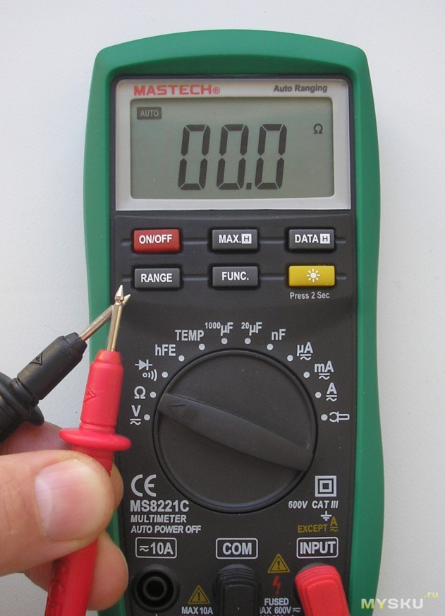
I touch the probes of the multimeter in the mode of sound continuity of the PWM controller legs - suddenly a beep sounds, I remove the probes in order to call the rest of the legs, the signal sounds for another 2 seconds. Well, I think that's all: again 2 resistors burned out, one in the resistance measurement circuit of the 2 kOhm mode, for 900 Ohm, the second for 1.5 - 2 kOhm, which is most likely in the ADC protection circuits. I had already encountered a similar nuisance, in the past a friend hit me with a tester in the same way, so I did not get upset - I went to the radio store for two resistors in SMD cases 0805 and 0603, one ruble a piece, and soldered them.
| Video (click to play). |
Searches for information on the repair of multimeters on various resources, at one time, gave out several typical schemes, on the basis of which most models of cheap multimeters are built. The problem was that the reference designations on the boards did not match the designations on the found diagrams.
Burnt resistors on the multimeter board
But I was lucky, on one of the forums a person described in detail a similar situation, the failure of the multimeter when measuring with the presence of voltage in the circuit, in the mode of sound dialing. If there were no problems with the 900 Ohm resistor, several resistors on the board were connected in a chain and it was easy to find it. Moreover, for some reason it did not turn black, as is usually the case during combustion, and it was possible to read the denomination and try to measure its resistance. Since the multimeter contains precise resistors that have 4 digits in their designation, it is better, if possible, to change the resistors to exactly the same ones.
There were no precision resistors in our radio store and I took the usual one for 910 ohms. As practice has shown, the error with such a replacement will be quite insignificant, because the difference between these resistors, 900 and 910 Ohms, is only 1%. Determining the value of the second resistor was more difficult - from its terminals there were tracks to two transition contacts, with metallization, to the back of the board, to the switch.
Place for soldering thermistor
But I was lucky again: two holes were left on the board connected by tracks in parallel with the resistor leads and they were signed by RTS1, then everything was clear. The thermistor (РТС1), as we know from the pulse power supplies, is soldered in order to limit the currents through the diodes of the diode bridge when the pulsed power supply is turned on.
Since electrolytic capacitors, those very large barrels of 200-400 volts, at the moment the power supply is turned on and the first fractions of a second at the start of charging, behave almost like a short circuit - this causes large currents through the bridge diodes, as a result of which the bridge can burn out.
To put it simply, a thermistor has a low resistance in normal mode when small currents flow, corresponding to the mode of operation of the device. With a sharp multiple increase in current, the resistance of the thermistor also increases sharply, which, according to Ohm's law, as we know, causes a decrease in the current in the circuit section.
Resistor 2 Kom Ohm on the diagram
When repairing on the circuit, presumably we change to a 1.5 kΩ resistor, the resistor indicated on the circuit with a nominal value of 2 kΩ, as they wrote on the resource from which they took the information, during the first repair, its value is not critical and it was recommended to put it, nevertheless, at 1.5 kΩ.
We continue... After the capacitors are charged and the current in the circuit has decreased, the thermistor decreases its resistance and the device operates normally.
900 ohm resistor on the diagram
Why is a thermistor installed instead of this resistor in expensive multimeters? With the same purpose as in switching power supplies - to reduce large currents that can lead to the burnout of the ADC, arising in our case as a result of an error of the master conducting the measurements, and thereby protecting the analog-to-digital converter of the device.
Or, in other words, that very black drop, after the combustion of which the device usually no longer makes sense to restore, because this is a laborious task and the cost of parts will exceed at least half the cost of a new multimeter.
How can we solder these resistors - perhaps beginners who have not previously dealt with SMD radio components will think. After all, they most likely do not have a soldering hair dryer in their home workshop. There are three ways here:
- First, you will need an EPSN soldering iron with a power of 25 watts, with a blade blade with a cut in the middle, in order to heat both terminals at once.
- The second way, by biting off with side cutters, a drop of Rose or Wood's alloy, immediately on both contacts of the resistor, and flatten both of these terminals with a sting.
- And the third way, when we have nothing but a 40-watt soldering iron of the EPSN type and the usual POS-61 solder - we apply it to both leads so that the solders mix and as a result, the total melting temperature of the lead-free solder decreases, and we heat both leads of the resistor alternately, while trying to move it a little.
Usually this is enough for our resistor to be sealed off and stick to the tip. Of course, do not forget to apply the flux, it is better, of course, liquid Alcohol rosin flux (GFR).
In any case, no matter how you dismantle this resistor from the board, bumps of old solder will remain on the board, we need to remove it using a dismantling braid, dipping it in an alcohol-rosin flux. We put the tip of the braid directly on the solder and press it, warming it up with the tip of the soldering iron until all the solder from the contacts is absorbed into the braid.
Well, then it's a matter of technology: we take the resistor we bought from the radio store, put it on the contact pads that we freed from the solder, press it down with a screwdriver from above and touch the pads and leads located on the edges of the resistor with the tip of a 25-watt soldering iron, solder it in place.
Solder Braid - Applications
The first time, it will probably turn out crooked, but the most important thing is that the device will be restored. On the forums, opinions about such repairs were divided, some argued that due to the cheapness of multimeters, it makes no sense to repair them at all, they say they threw it out and went to buy a new one, others were even ready to go all the way and re-solder the ADC). But as this case shows, sometimes repairing a multimeter is quite simple and cost-effective, and any home craftsman can easily handle such a repair. Successful repairs to everyone! AKV.
Experts advise starting the search for the cause of the malfunction with a thorough examination of the printed circuit board, since short circuits and poor soldering are possible, as well as a defect in the leads of the elements along the edges of the board.
Factory defect in these devices is manifested mainly on the display. There can be up to ten types of them (see table). Therefore, it is better to repair digital multimeters using the instructions that come with the device.
The same breakdowns can occur after operation. The above malfunctions may also appear during operation. However, if the device operates in constant voltage measurement mode, it rarely breaks.
The reason for this is its overload protection. Also, the repair of a faulty device should begin with checking the supply voltage and the operability of the ADC: the stabilization voltage is 3 V and there is no breakdown between the power pins and the common ADC output.
Experienced users and professionals have repeatedly stated that one of the most likely causes of frequent breakdowns in the device is poor quality production. Namely, soldering contacts with acid. As a result, the contacts are simply oxidized.
However, if you are not sure what kind of breakdown caused the inoperative state of the device, you should still contact a specialist for advice or help.
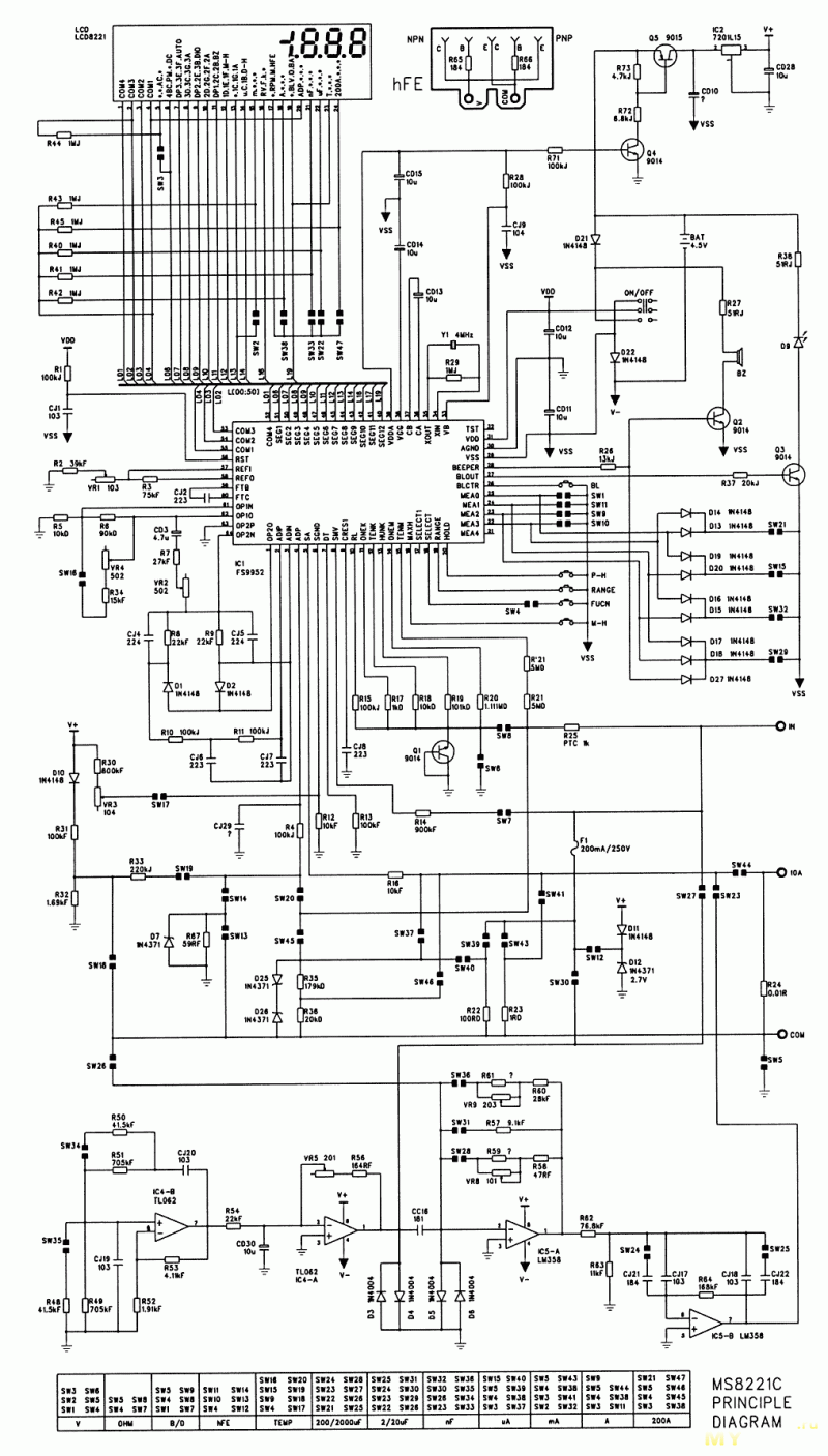
such a good multimeter MS8221C. has served faithfully and truthfully for a year and a half. but got on a charged capacity. diodes D5, D6 and lm358 and tl062 microcircuits have been replaced. Now the voltage, resistance measures. The temperature shows as in hell AZH 337 CELSIUS AND 640 FARENHEIT. and the most annoying thing about measuring the capacity is no reaction. c meter what to buy ??
mastech_ms8221c.zip 111.86 KB Downloaded: 2455 times
thanks mix! 1. shoveled everything = that's why I'm asking. 2.This multimeter with automatic measuring limit. Where to supply what and how to choose 2V? 3. I would like to know what kind of ADC is there? And what is the difference between measuring resistance and measuring capacitance in this device? NEVER REPAIR multimeters: but I would like to cure this one .. explain to a non-metrologist. PLEASE.
I'm correcting myself: I set the voltage to 2 volts by pressing the range button 3 times: everything works, so I wrote that it measures the voltage. I would have thrown it out, but it measures everything correctly around the capacity and temperature.
WASA, tried to figure out your scheme. In general, a datasheet for your microcircuit (FS9952) on the manufacturer's website. It also contains simplified circuits for measuring individual parameters using this ADC.
There were obvious bugs in the scheme .. (non-printing of connection points, bloopers in switch positions). So, for example, in the resistance measurement mode, the GND input, according to the table of switch states at the bottom of the circuit, simply hangs in the air - that is, it is not connected to anything. From this, it is easier to redraw this plate (or check the diagram) on a real device (I don’t have such an opportunity, due to the absence of the device itself), rather than trying to understand “how it could be if it were. ”According to this scheme.
Further, about the capacity: rummage in the circuit on the op-amp IC4, IC5 - the master oscillator of the capacitance meter is assembled on IC4A, IC4B is the “saw” amplifier, IC5A is not a comparator (if the connection point of CC16 with diodes D5, D6 is really absent), not a normalizing gain for ranges (if it does have a place to be). On the IC5B, to be honest, I myself did not understand why, some kind of bandpass filter is stuck together. But the absence of soldering points of the R64 resistor with CJ17 and CJ18 is already a clear indication that another tester is needed for repair, a paper printout of the circuit and a large felt-tip pen - these points simply CANNOT be missing in this circuit. In general, if everything else works the rules, most likely the dog has rummaged somewhere.
PS: and if you believe the table of switch positions - capacities from 20 to 200 μF, this tester simply does not measure.But it is absolutely incomprehensible what the tester does in B / O mode.
Further - in the temperature measurement mode, you can forget about the node described above, however (again, according to the table of switch positions), purely for measuring the temperature, some adjustment of the reference signal on the 61st leg of IC1 by the VR4 resistor is turned on (Set 0 deg? too lazy to paint the device circuit together with the ADC block diagram, besides, with so many errors on the circuit), in addition, some kind of adjustment by the VR3 resistor on the 7th leg (DT) of the ADC is turned on, through SW18 at the input. COM, the internal reference (bias?) Voltage is supplied from the D10, R31, R32 chains, and it is fed through R33, R4 to the 6th leg (SGND) of the ADC. Well, even R21, R * 21 would not hurt to check. unless, of course, from the connection point SW20, SW45 to them there really are no connections - again, if you believe the table of switch positions, these resistors work only in TEMP and 200A modes. Again, digging these chains makes sense if the phrase is true. " in all other modes it works fine. "
AND, WASA, since it's all the same for you to climb into this device - as a thank you to the forum, you can draw unmarked ration points on the diagram (you can in paper form, then scan it, or you can in Photoshop on the source), and bloopers in the table of switch positions, and then put it here ... The device is relatively new, but I feel that there will be no more questions about it soon. There is already a second one. And correct the topic - so that all questions about this unit are not piled into one heap.
PS: by the way, I did not find IC3 on the circuit. On the board, too, this does not have a place to be?
Another multimeter from the MASTECH family with its own advantages and disadvantages. The device deserves to be examined more closely.
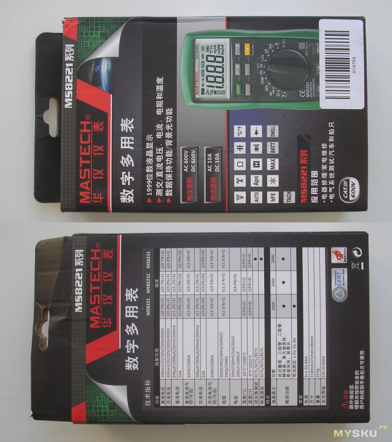
We look in what form they send.
The box is for this series.
On the reverse side of the characteristics.
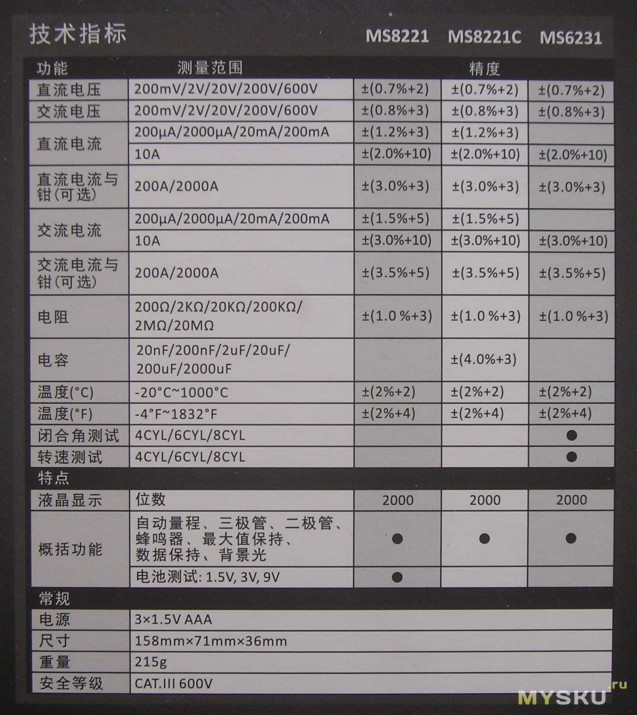
Moving on to what's inside.
The multimeter with the device was in a dense "permeated" plastic bag.
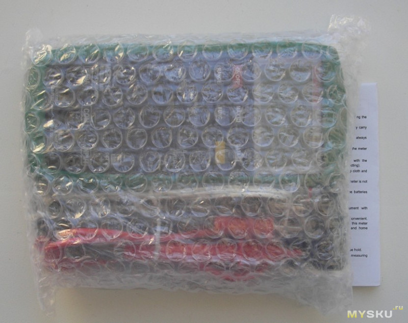
Package Included:
- multimeter
- probes
- thermocouple
- adapter adapter
- instruction
- warranty card.
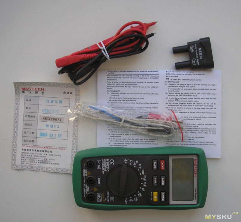
Instruction in English - photocopy of A4 format (3 pages on two sheets).
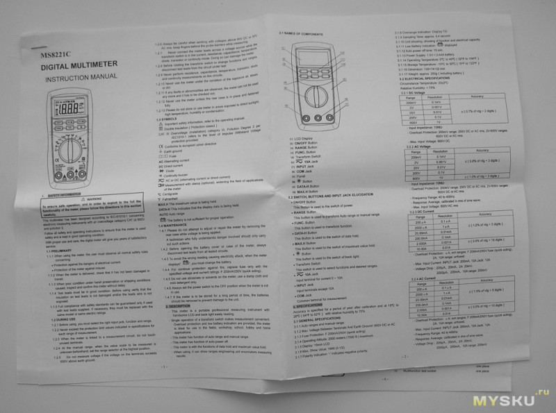
And these are links to scans of instructions for the multimeter: 1,2,3. Perhaps it will be useful to someone.
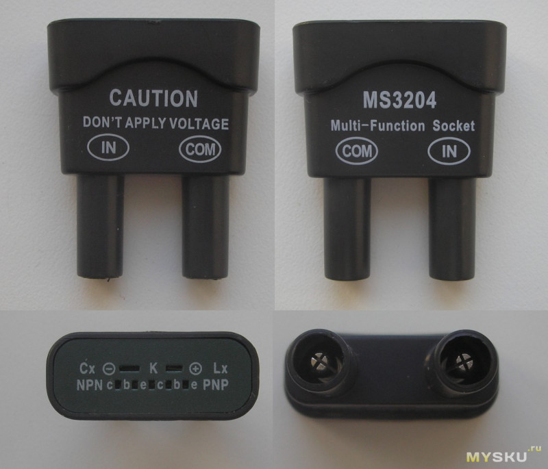
Adapter adapter.
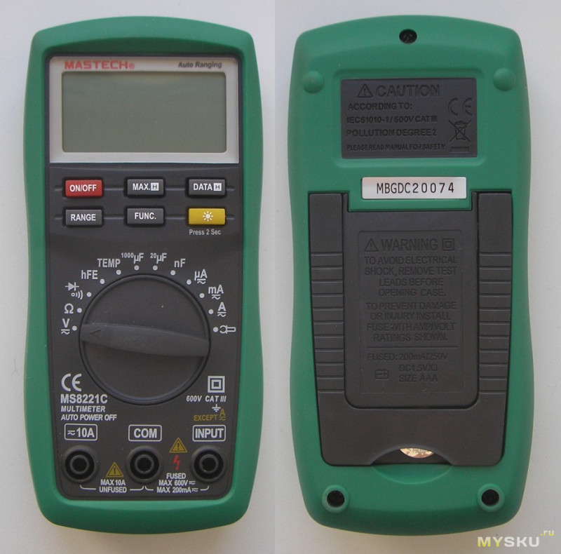
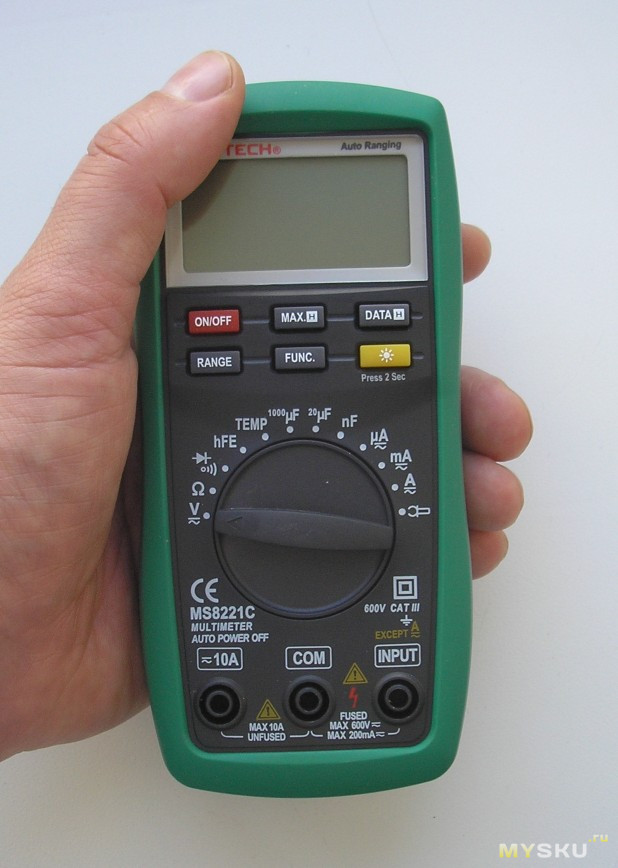
And here is the multimeter. Small in size.
Looks very neat. Slightly smaller than average.
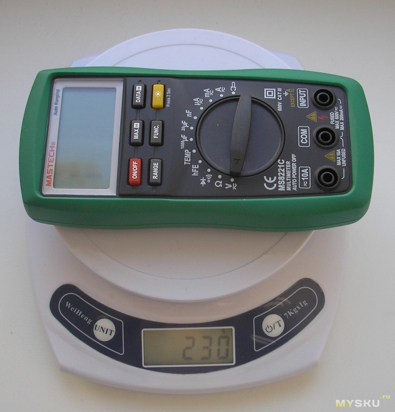
Weighed it. 230g. (with batteries).
In the counterpart for the screws there are two bronze bushings.
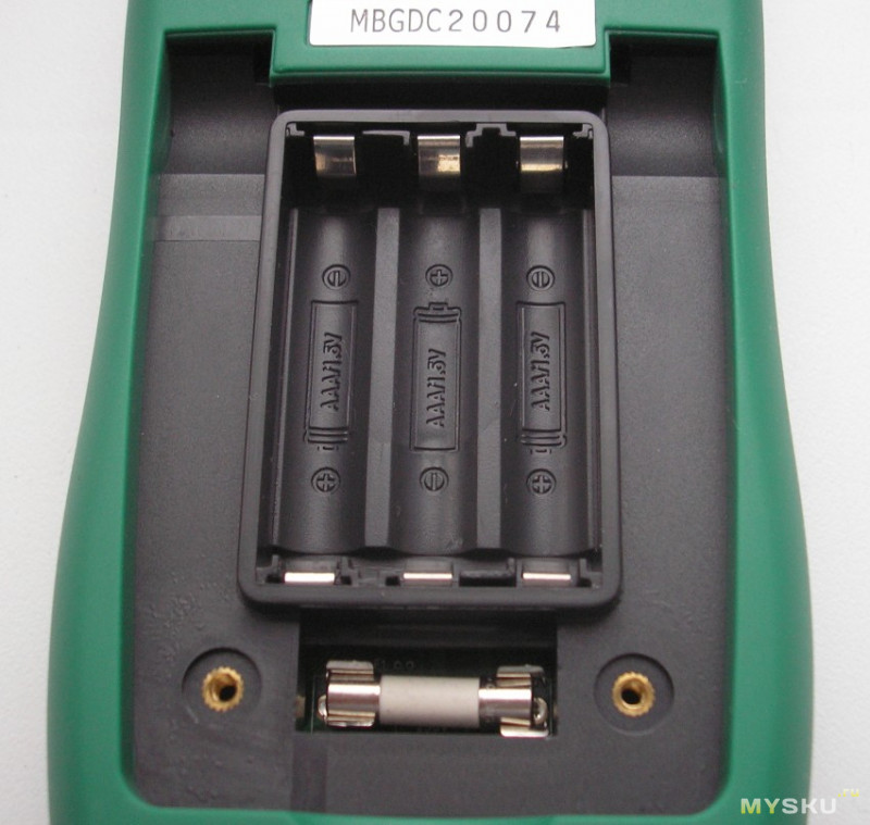
It is not necessary to disassemble the multimeter to change the fuse.
I think AAA batteries are a plus. Not included in the package.
To determine plus and minus, you need to look at the reflection. This is not entirely good.
The contact pads are well spring loaded.
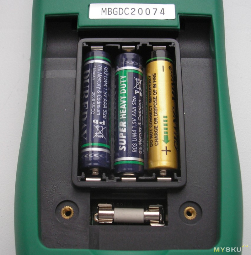
Can be turned over without lid. The batteries will not fall out.
I turn to the analysis.
A "silicone" case is implanted into each half. Was originally smelled. After a while, the smell disappeared.
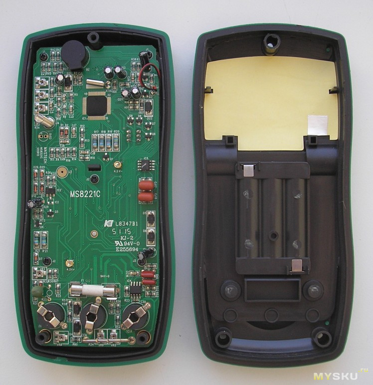
I unscrew three screws.
Then he unscrewed 3 more screws for fastening the switch.
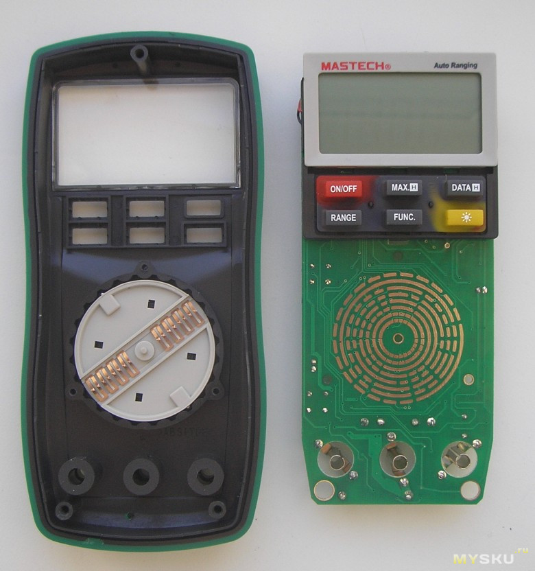
To remove the display, I unscrewed two more screws.
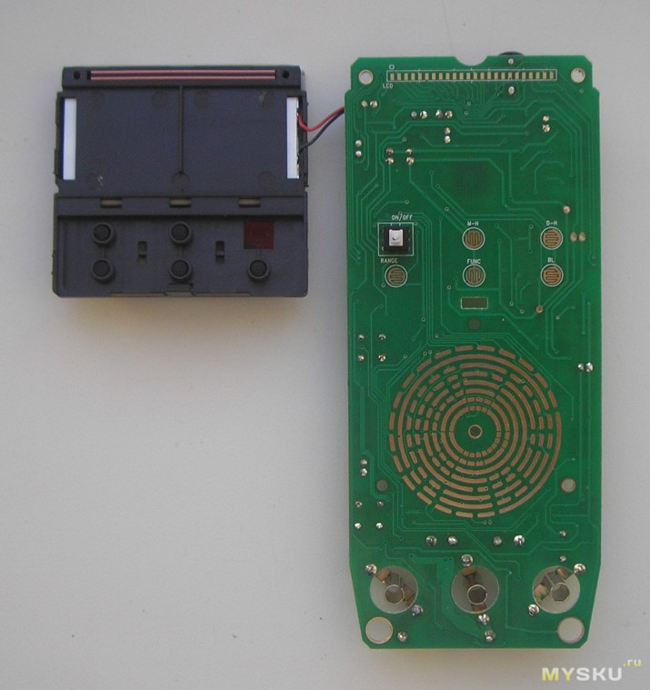
If you look at the reflection, you can see that the contact pads are in grease.
There are 7 trimming resistors inside. The purpose of each is not clear, they are not signed.
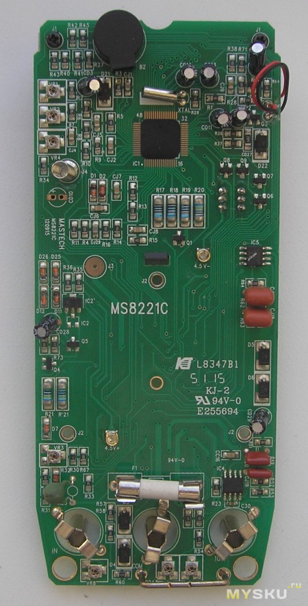
You can see everything in more detail.
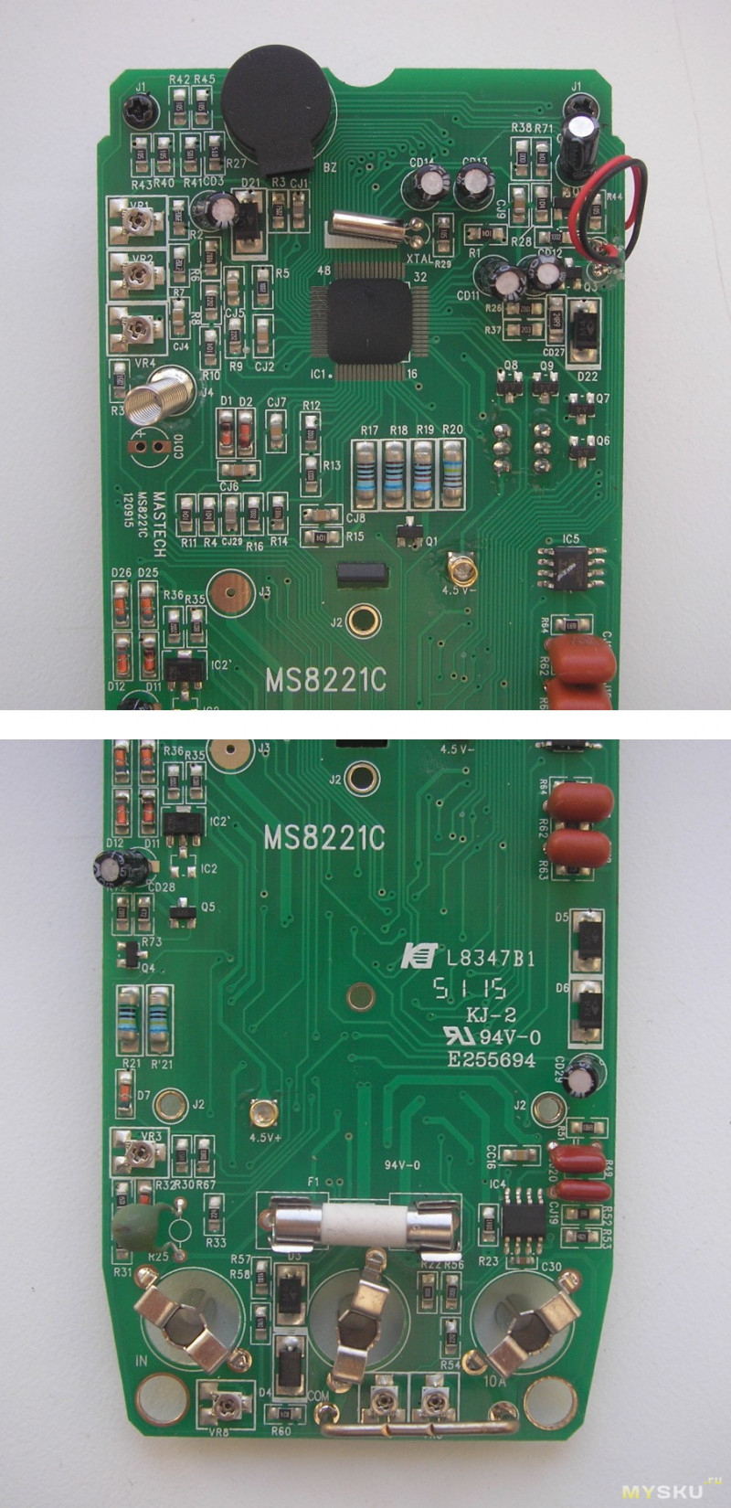
Soldering without comment. A blot-type microcircuit is used as a "brain". Well, a very neat "blot".
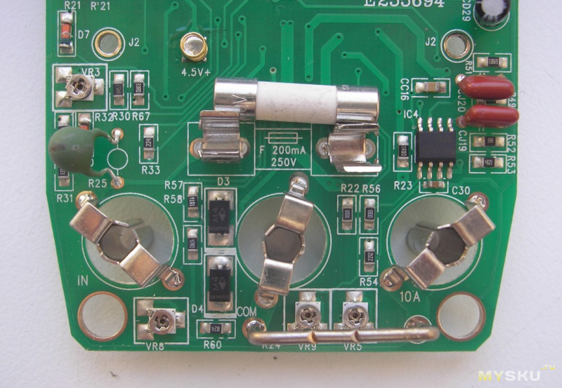
There is a 200mA 250V fuse at the current input. There is no fuse for 10A. It is replaced by printed conductors :)
Measures constant very well. The measurement accuracy is much higher than stated.
The indicator of the multimeter shows not only numbers, but also the measured values (V, mV). I will check the DC measurements on the P321 installation. The principle is the same as when measuring voltage.
Declared error:
DC Current: 200µA / 2000µA / 20mA / 200mA + - (1.2% + 3); 2A / 10A + - (2.0% + 10)
Not bad too, although slightly worse than when measuring DC voltage.
When the measurement limit is exceeded, it beeps (beeps).
Let's move on to measuring resistance.
To assess the accuracy of measurements, I used P4834 and P4002. I also put all the data in a table.
Declared error:
Resistance: 200Ω + - (1.0% + 3); 2kΩ / 20kΩ / 200kΩ / 2MΩ + - (1.0% + 1); 20MΩ + - (1.0% + 5).
A very good result. Measurement error of a fraction of a percent.
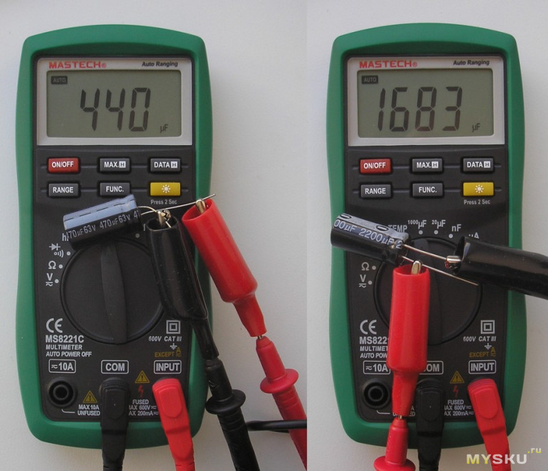
The accuracy of measuring the containers was checked using the P5025 magazine.
The declared error on the store's website:
Capacitance: 20nF + - (4.0% + 10); 200nF / 2µF / 20µF / 200µF / 1000µF + - (4.0% + 3).
It measures poorly on the 20nF sub-band. I have no comments on the remaining limits.
Measures capacities quickly, without brakes.
It is stated that the multimeter measures capacitances only up to 1000uF. In fact, it measures up to 2000μF, but above 1000μF, the error is not standardized.
The ringing diodes and the buzzer are separated into different modes. To select the mode, use the "FUNC." Button. When the diodes are ringing on open probes 1.57V. LEDs are not illuminated :(
When ringing the chain, I did not notice the braking effect. For those who are critical of this indicator, watch the video.
In buzzer mode 0.45V. These are actually measured readings.
Can measure temperature.
Standard K-type thermocouple.
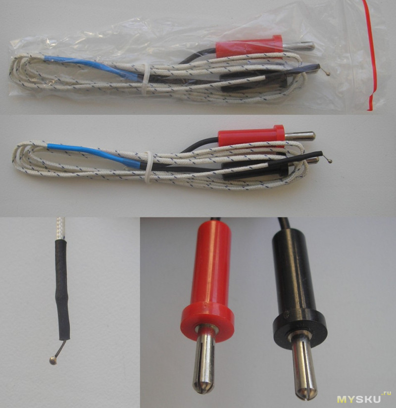
I cannot thoroughly check the temperature. Checked several points.
I didn't like what it measures in Fahrenheit when turned on. Every time you have to switch.
Armpit temperature.
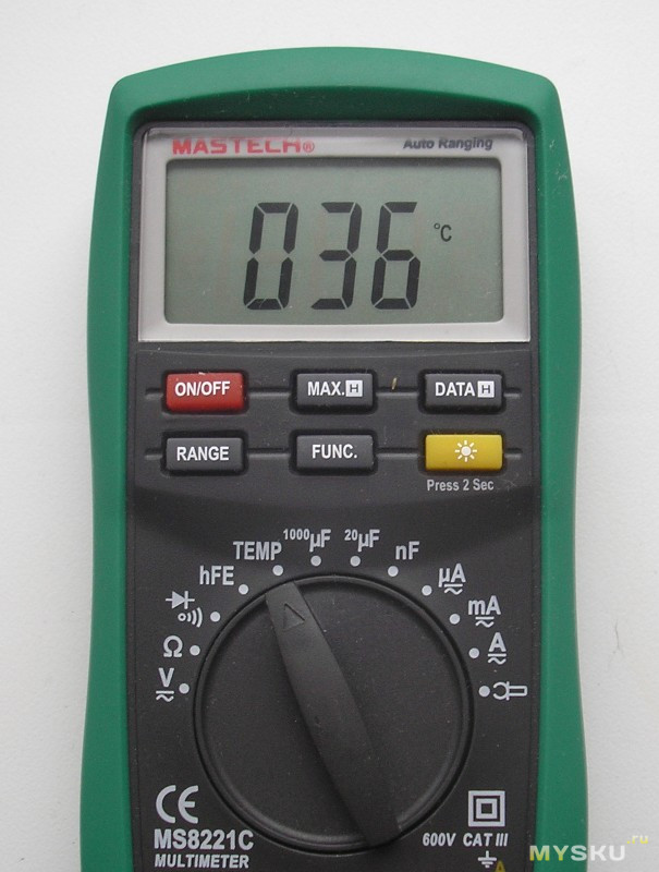
I measured it in boiling water.
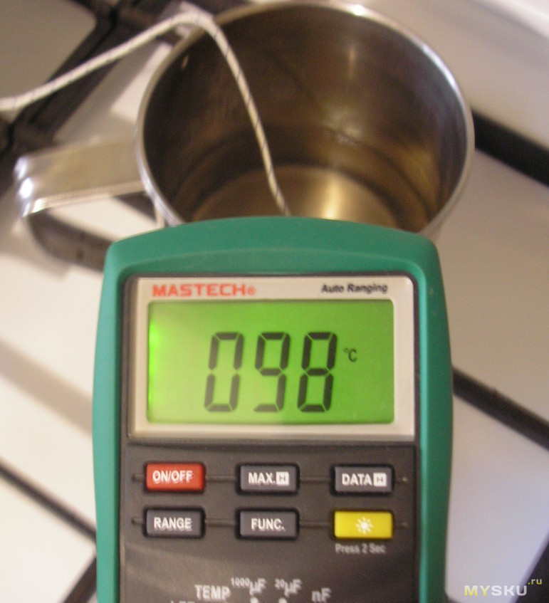
I researched the main thing. I decided to go back to measuring AC voltage.
I downloaded the diagram from the Internet.
Analyzed. VR2 is responsible for correcting the AC signal measurements. Spun clockwise a little. Clockwise rotation increases the meter reading. I checked it against an exemplary counter. Now everything suits me. On other subranges of measuring alternating voltage, the measurement error also changed. But everything is within the class. Where the multimeter used to underestimate, now it overestimates a little by about the same value. But I consider the accuracy of measuring the mains voltage to be more important for myself.
The product is provided for writing a review by the store. The review is published in accordance with clause 18 of the Site Rules.
The MS8221C multimeter. has served faithfully for a year and a half. and the most annoying thing about measuring the capacity is no reaction. help with advice.
mastech_ms8221c.zip 111.86 KB Downloaded: 731 times
This article describes the device of the 830 series digital multimeters, its circuit, as well as the most common malfunctions and how to fix them.
Currently, a huge variety of digital measuring instruments of varying degrees of complexity, reliability and quality are produced. The basis of all modern digital multimeters is an integrated analog-to-digital voltage converter (ADC). One of the first such ADCs suitable for constructing inexpensive portable measuring instruments was a converter based on the ICL7106 microcircuit manufactured by MAXIM. As a result, several successful low-cost models of 830 series digital multimeters have been developed, such as M830B, M830, M832, M838. DT can be used instead of the letter M. This instrument series is currently the most widespread and most repeatable in the world. Its basic capabilities: measuring direct and alternating voltages up to 1000 V (input resistance 1 MΩ), measuring direct currents up to 10 A, measuring resistances up to 2 MΩ, testing diodes and transistors. In addition, in some models there is a mode of sound continuity of connections, temperature measurement with and without a thermocouple, generation of a meander with a frequency of 50 ... 60 Hz or 1 kHz. The main manufacturer of this series of multimeters is Precision Mastech Enterprises (Hong Kong).
The basis of the multimeter is the ADC IC1 of the 7106 type (the closest domestic analogue is the 572PV5 microcircuit). Its structural diagram is shown in Fig. 1, and the pinout for the version in the DIP-40 package is shown in Fig. 2. The 7106 core can be preceded by different prefixes depending on the manufacturer: ICL7106, ТС7106, etc. Recently, more and more often used are chipless microcircuits (DIE chips), the crystal of which is soldered directly to the printed circuit board.
Consider the circuit of the Mastech M832 multimeter (Fig. 3). Pin 1 of IC1 supplies a positive 9V battery supply voltage, and Pin 26 supplies a negative battery supply. Inside the ADC there is a 3 V stabilized voltage source, its input is connected to pin 1 of IC1, and the output is connected to pin 32. Pin 32 is connected to the common pin of the multimeter and is galvanically connected to the COM input of the device. The voltage difference between pins 1 and 32 is approximately 3 V in a wide range of supply voltages - from nominal to 6.5 V. This stabilized voltage is fed to the adjustable divider R11, VR1, R13, and from its output to the input of the microcircuit 36 (in the mode measurements of currents and voltages). The divider sets the potential U at pin 36, equal to 100 mV. Resistors R12, R25 and R26 perform protective functions. Transistor Q102 and resistors R109, R110 and R111 are responsible for indicating the discharge of the battery. Capacitors C7, C8 and resistors R19, R20 are responsible for displaying the decimal points of the display.
Operating input voltage range Umax directly depends on the level of the regulated reference voltage at pins 36 and 35 and is
The stability and accuracy of the display is dependent on the stability of this reference voltage.
The display N readings depend on the input voltage U and are expressed as a number
A simplified circuit of the multimeter in the voltage measurement mode is shown in Fig. 4.
When measuring DC voltage, the input signal is fed to R1… R6, from the output of which, through a switch [according to the scheme 1-8 / 1… 1-8 / 2), it is fed to the protective resistor R17. This resistor also forms a low-pass filter when measuring AC voltage together with the capacitor C3. Then the signal goes to the direct input of the ADC microcircuit, pin 31. The potential of the common pin, generated by the 3 V stabilized voltage source, pin 32, is fed to the inverse input of the microcircuit.
When measuring AC voltage, it is rectified by a half-wave rectifier on diode D1. Resistors R1 and R2 are selected so that when measuring sinusoidal voltage, the device shows the correct value. ADC protection is provided by the divider R1 ... R6 and the resistor R17.
A simplified circuit of the multimeter in the current measurement mode is shown in Fig. 5.
In the mode of measuring direct current, the latter flows through the resistors R0, R8, R7 and R6, which are switched depending on the measuring range. The voltage drop across these resistors through R17 is fed to the ADC input, and the result is displayed. ADC protection is provided by diodes D2, D3 (in some models they may not be installed) and fuse F.
A simplified circuit of the multimeter in the resistance measurement mode is shown in Fig. 6. In the resistance measurement mode, the dependence expressed by the formula (2) is used.
The diagram shows that the same current from the voltage source + U flows through the reference resistor and the measured resistor R "(the currents of inputs 35, 36, 30 and 31 are negligible) and the ratio of U and U is equal to the ratio of the resistances of the resistors R" and R ^. R1..R6 are used as reference resistors, R10 and R103 are used as current setting resistors. Protection of the ADC is provided by thermistor R18 (some cheap models use conventional 1.2 kΩ resistors), transistor Q1 in zener diode mode (not always installed) and resistors R35, R16 and R17 at inputs 36, 35 and 31 of the ADC.
Continuity mode The dialing circuit uses IC2 (LM358), which contains two operational amplifiers.A sound generator is assembled on one amplifier, and a comparator on the other. When the voltage at the input of the comparator (pin 6) is less than the threshold, a low voltage is set at its output (pin 7), which opens the switch on the transistor Q101, as a result of which a sound signal is emitted. The threshold is determined by the divider R103, R104. Protection is provided by resistor R106 at the comparator input.
All malfunctions can be divided into factory defects (and this happens) and damage caused by erroneous actions of the operator.
Since multimeters use tight wiring, shorts of elements, poor soldering and breakage of the leads of elements, especially those located at the edges of the board, are possible. Repair of a faulty device should begin with a visual inspection of the printed circuit board. The most common factory defects of M832 multimeters are shown in the table.
The LCD display can be checked for proper operation using a 50.60 Hz AC voltage source with an amplitude of several volts. As such a source of alternating voltage, you can take the M832 multimeter, which has a meander generation mode. To check the display, put it on a flat surface with the display up, connect one probe of the M832 multimeter to the common terminal of the indicator (bottom row, left terminal), and apply the other probe of the multimeter alternately to the rest of the display. If it is possible to get the ignition of all segments of the display, then it is serviceable.
The above malfunctions may also appear during operation. It should be noted that in the DC voltage measurement mode, the device rarely fails, because well protected from input overloads. The main problems arise when measuring current or resistance.
Repair of a faulty device should begin with checking the supply voltage and ADC operability: stabilization voltage of 3 V and no breakdown between the power pins and the common ADC output.
In the current measurement mode when using the V, Q and mA inputs, despite the presence of a fuse, there may be cases when the fuse blows out later than the safety diodes D2 or D3 have time to break through. If a fuse is installed in the multimeter that does not meet the requirements of the instructions, then in this case the resistances R5 ... R8 may burn out, and this may not appear visually on the resistances. In the first case, when only the diode breaks through, the defect appears only in the current measurement mode: the current flows through the device, but the display shows zeros. In case of burnout of resistors R5 or R6 in the voltage measurement mode, the device will overestimate the readings or show an overload. When one or both resistors are completely burned out, the device is not reset in voltage measurement mode, but when the inputs are closed, the display is set to zero. When the resistors R7 or R8 burn out on the current measuring ranges of 20 mA and 200 mA, the device will show an overload, and in the 10 A range - only zeros.
In resistance measurement mode, faults usually occur in the 200 ohm and 2000 ohm ranges. In this case, when voltage is applied to the input, resistors R5, R6, R10, R18, transistor Q1 and capacitor C6 can burn out. If the transistor Q1 is completely punctured, then when measuring the resistance, the device will show zeros. In case of incomplete breakdown of the transistor, the multimeter with open probes will show the resistance of this transistor. In the modes of measuring voltage and current, the transistor is short-circuited by a switch and does not affect the readings of the multimeter. With a breakdown of capacitor C6, the multimeter will not measure voltage in the ranges of 20 V, 200 V and 1000 V or significantly underestimate the readings in these ranges.
If there is no indication on the display, when there is power to the ADC, or there is a visually noticeable burnout of a large number of circuit elements, there is a high probability of damage to the ADC. Serviceability of the ADC is checked by monitoring the voltage of the 3 V stabilized voltage source.In practice, the ADC burns out only when a high voltage is applied to the input, much higher than 220 V. Very often, cracks appear in the compound of an open-frame ADC, the current consumption of the microcircuit increases, which leads to its noticeable heating.
When a very high voltage is applied to the input of the device in the voltage measurement mode, a breakdown may occur in the elements (resistors) and on the printed circuit board, in the case of the voltage measurement mode, the circuit is protected by a divider on the resistances R1.R6.
For cheap DT series models, long parts leads can be shorted to the screen located on the back of the device, disrupting the operation of the circuit. Mastech does not have such defects.
A source of a stabilized voltage of 3 V in an ADC for cheap Chinese models can in practice give a voltage of 2.6-3.4 V, and for some devices it stops working already at a voltage of a supply battery of 8.5 V.
The DT models use low quality ADCs and are very sensitive to the C4 and R14 integrator chain ratings. High-quality ADCs in Mastech multimeters allow the use of elements of close denominations.
Often, in DT multimeters, when the probes are open in the resistance measurement mode, the device approaches the overload value for a very long time ("1" on the display) or is not set at all. It is possible to "cure" a poor-quality ADC microcircuit by reducing the value of the resistance R14 from 300 to 100 kOhm.
When measuring resistances in the upper part of the range, the device "flushes" the readings, for example, when measuring a resistor with a resistance of 19.8 kOhm, it shows 19.3 kOhm. It is "treated" by replacing the capacitor C4 with a capacitor of 0.22 ... 0.27 μF.
Since cheap Chinese firms use low-quality unpackaged ADCs, there are frequent cases of broken pins, and it is very difficult to determine the cause of the malfunction and it can manifest itself in different ways, depending on the broken pin. For example, one of the indicator leads is off. Since multimeters use displays with static indication, then to determine the cause of the malfunction, it is necessary to check the voltage at the corresponding pin of the ADC microcircuit, it should be about 0.5 V relative to the common pin. If it is zero, then the ADC is faulty.
There are malfunctions associated with poor-quality contacts on the biscuit switch, the device works only when the biscuit is pressed. Firms that make cheap multimeters rarely coat the tracks under the rocker switch with grease, which is why they quickly oxidize. Often the tracks are dirty. It is repaired as follows: the printed circuit board is removed from the case, and the switch tracks are wiped with alcohol. Then a thin layer of technical petroleum jelly is applied. Everything, the device is repaired.
With DT series devices, it sometimes happens that the alternating voltage is measured with a minus sign. This indicates an incorrect installation of D1, usually due to incorrect marking on the diode body.
It happens that manufacturers of cheap multimeters put low-quality operational amplifiers in the sound generator circuit, and then when the device is turned on, a buzzing buzzer is heard. This defect is eliminated by soldering a 5 μF electrolytic capacitor parallel to the power supply circuit. If this does not ensure the stable operation of the sound generator, then it is necessary to replace the operational amplifier with the LM358P.
Often there is such a nuisance as battery leakage. Small drops of electrolyte can be wiped off with alcohol, but if the board is heavily flooded, then good results can be obtained by washing it with hot water and laundry soap. After removing the indicator and unsoldering the buzzer, using a brush, for example, a toothbrush, you need to thoroughly soap the board on both sides and rinse it under running water from the tap. After repeating the wash 2.3 times, the board is dried and installed in the case.
Most recently manufactured devices use DIE chips ADCs.The crystal is installed directly on the PCB and is filled with resin. Unfortunately, this significantly reduces the maintainability of the devices, because when the ADC fails, which is quite common, it is difficult to replace it. Unpackaged ADCs are sometimes sensitive to bright light. For example, if you work near a table lamp, the measurement error may increase. The fact is that the indicator and the board of the device have some transparency, and light, penetrating through them, enters the ADC crystal, causing a photoelectric effect. To eliminate this drawback, you need to remove the board and, after removing the indicator, glue the location of the ADC crystal (it is clearly visible through the board) with thick paper.
When buying DT multimeters, you should pay attention to the quality of the switch mechanics; be sure to rotate the multimeter's rocker switch several times to make sure that the switching occurs clearly and without jamming: plastic defects cannot be repaired.
Sergey Bobin. "Repair of electronic equipment" No. 1, 2003
It is quite within the power of every user who is well acquainted with the basics of electronics and electrical engineering to independently organize and repair the multimeter. But before embarking on such a repair, you must try to figure out the nature of the damage that has occurred.
It is most convenient to check the serviceability of the device at the initial stage of repair by inspecting its electronic circuit. For this case, the following troubleshooting rules have been developed:
it is necessary to carefully examine the printed circuit board of the multimeter, on which there may be clearly distinguishable factory defects and errors;
- special attention should be paid to the presence of unwanted short circuits and poor-quality soldering, as well as defects on the terminals at the edges of the board (in the area of the display connection). For repairs, you will have to use soldering;
- factory errors most often manifest themselves in the fact that the multimeter does not show what it should according to the instructions, and therefore its display is examined first of all.
If the multimeter gives incorrect readings in all modes and IC1 heats up, then you need to inspect the connectors to check the transistors. If the long leads are closed, then the repair will consist only in opening them.

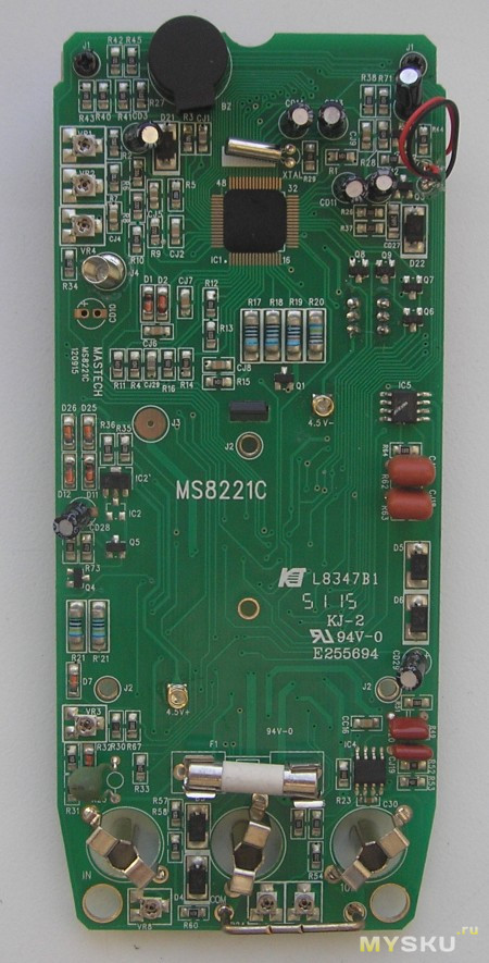

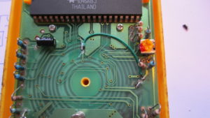 it is necessary to carefully examine the printed circuit board of the multimeter, on which there may be clearly distinguishable factory defects and errors;


