Details: nissan almera classic do-it-yourself gearbox repair from a real master for the site my.housecope.com.
The main malfunctions, for the elimination of which it is necessary to remove the gearbox from the car:
- increased (compared to the usual) noise;
- spontaneous switching off or fuzzy switching on of gears;
- oil leakage through seals and gaskets.
In addition, the gearbox is removed prior to replacing the clutch, flywheel, and crankshaft rear oil seal.
HELPFUL TIPS: The work of removing and installing the gearbox is very laborious, so be sure to first make sure that its malfunctions are not caused by other reasons (insufficient oil level, defects in the clutch release drive, loosening of the gearbox fastening, etc.).
The gearbox is quite heavy and its shape is inconvenient to hold, so we recommend removing it with an assistant.
You will need: keys "for 14" and "for 24".
1. Drain the oil from the transmission (see "Checking the level and changing the oil in a manual transmission").
2. Remove drives of front wheels (see "Removal and installation of drives of front wheels).
3. Remove the starter (see "Removal and installation of the starter").
4. Disconnect the harness connector from the reverse light switch (see "Replacing the reverse light switch").
5. Disconnect the harness connector from the transmission neutral position sensor.
6.. and remove the harness holders from the holes in the transmission housing.
7. Remove the clutch slave cylinder mounting bolts, and then, without disconnecting the hose from it, remove the cylinder from the transmission and take it to the side (see "Replacing the clutch slave cylinder").
| Video (click to play). |
8. Unscrew the nut of the axle securing the selection rod to the bushing of the selection mechanism.
9. . remove the axle and remove the link bracket from the hub.
10. Unscrew two bolts of terminals of "earth" wires and remove the terminals from the transmission.
11. Place supports under the engine crankcase and the gearbox housing, remove the protective bar and the left support of the power unit (see "Replacing the suspension mounts of the power unit and the protective bar").
12. Remove the two bolts of the front fastening of the gearbox to the cylinder block.
thirteen. . and two top mounting bolts.
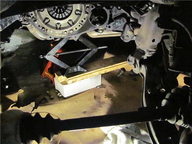
14. Move the gearbox back until the input shaft of the gearbox leaves the clutch disc hub. Then slide the gearbox back as far as possible, remove the support from under it and, tilting the rear part of the gearbox down, remove it from the car.
WARNING: When removing the transmission, do not rest the end of the input shaft against the diaphragm spring petals to avoid deforming them.
15. Establish a transmission, as well as all removed parts and assemblies in the reverse order of removal.
HELPFUL TIPS: Before installing the gearbox, lubricate the splines of the input shaft with a thin layer of refractory grease. Check how the clutch disc is centered using a special mandrel (see "Removing and installing the clutch").
16. Fill the transmission with oil (see "Checking the level and changing the oil in a manual transmission").
17. If necessary, adjust the transmission control drive (see "Adjustment of the transmission control drive").
Overhaul of manual transmission, disassembly and assembly of units and components
Gear Shift Drive Components
1 - the Handle of the manual transmission control lever
2 - the control lever of the manual transmission
3 - Outer protective cover
4 - Internal protective cover
5 - the Jet rod
6 - Rubber stop
7 - the Fastening clamp
8 - the Bolt
9 - the Spacer sleeve
10 - the Lock ring
11 - the Distance washer
12 - Rubber rings
13 - Bushings of the spherical hinge
14 - Anther
15 - Bolt М6
16 - Washer
17 - the Rubber bushing
18 - Washer
19 - Draft of a drive of gear shifting
20 - Cardan joint
21 - the Coupling
22 - the Pin
23 - Plastic bushings
24 - bolt
25 - the Clamp of a traction
26 - a spring washer
27 - Nut М8 (18 Nm)
28 - Pin
5th gear assembly components manual transmission
1 - an adjusting washer
2 - Cage of the needle roller bearing of the gear wheel of the 5th transfer
3 - the inner race of the bearing
4 - the Leading gear wheel of the 5th transfer
5 - the Driven gear wheel of the 5th transfer
6 - Nut (60 Nm)
7 - the Blocking ring of the synchronizer
8 - the synchronizer spring
9 - the hub of the sliding coupling of the synchronizer
10 - Sliding key of the synchronizer
11 - Nut (60 Nm)
12 - Washer
13 - Support ring
14 - the Sliding coupling of the synchronizer
15 - the synchronizer spring
16 - the Fork of inclusion of the 5th transfer
17 - Pin 5x22 (must be replaced without fail)
The procedure for installing components of assemblies of the primary and secondary shafts of the manual transmission
1 - the Clutch dome
2 - Assembly of the main transfer
3 - Assembly of the secondary shaft
4 - the rod of the fork of inclusion of the 5th transfer
5 - Rod of forks of inclusion of 1/2 and 3/4 gears
6 - Assembling the input shaft
7 - Pin 4х7
8 - the Reverse gear lever pin
9 - the Plug
10 - the Lever of inclusion of a backing
11 - the ball of the retainer
12 - the Locking spring
13 - the intermediate gear wheel of a reverse
14 - the Pin
Input shaft of gearbox
1 - Inner race of tapered roller bearing
2 - Outer race of tapered roller bearings
3 - the Distance washer
4 - the Primary shaft
5 - Inner race of tapered roller bearing
6 - the outer cage of a tapered roller bearing
Components of the secondary shaft of the manual transmission box
1 - the Retaining ring
2 - Ball bearing
3 - the Gear wheel of the 4th transfer
4 - the synchronizer spring
5 - Sliding key of the synchronizer
6 - the hub of the sliding coupling of the synchronizer
7 - the Sliding coupling of the synchronizer
8 - the Lock ring
9 - the Blocking ring of the synchronizer
10 - Assembling the synchronizer 3/4 gears
11 - the Gear wheel of the 3rd transfer
12 - Washer
13 - Adjusting washer 2/3 gears
14 - the spring of the synchronizer
Gear Shift Components
1 - Sleeve of a rod of a fork of inclusion of transfers
2 - Coupling
3 - Pin 5x22 (must be replaced without fail during assembly)
4 - the Fork of inclusion of 1/2 transfers
5 - the Spike of the gear shifting mechanism
6 - cracker of the fixer
7 - Rod of forks of inclusion of 1/2 and 3/4 gears
8 - the Fork of inclusion of 3/4 transfers
9 - Rod sleeve
10 - the Lock bolt
11 - the Fork of inclusion of the 5th transfer
12 - Rod of a fork of inclusion of 5-1 transfer
13 - the Spike of the mechanism of switching of the 5th and reverse gears
14 - the Guide link
15 - the Gasket
16 - Bolt (10 Nm)
17 - Three-arm lever
18 - the pin of the three-legged lever
19 - Screw plug with an internal hexagon (30 Nm)
20 - Bolt (17 Nm, lubricate with Loctite sealant before installation)
21 - the Executive lever of a rod of a choice of transfers
22 - Thumb of the curtain
23 - the Pin with a spring
24 - the Pin with a spring
25 - the rod of selection of transfers
26 - the Sealing ring of the rod of choice
27 - Anther
28 - Locking spring
29 - retainer ball
30 - the Finger of the lever of inclusion of a reverse gear
31 - the Lever of inclusion of a reverse transfer
32 - the Plug
33 - Pin 4x25
Overhaul - general information
The overhaul of the manual transmission requires a high level of qualifications from the performer, since it involves the implementation of the exact setting of a variety of clearances, by selecting adjusting washers and spacer bushings. In addition, internal gearbox components are hard to find commercially, not to mention high prices. In view of the foregoing, the compilers of this Manual recommend, in the event of problems in the functioning of the manual transmission, to replace it with a new or refurbished unit.
Nevertheless, a sufficiently experienced amateur mechanic can easily perform gearbox repairs on his own, provided that he has a special tool. Remember that all procedures must be carried out in strict order. Do not rush, do not fuss, try not to miss any little things.
The number of special tools, without the use of which the repair of the manual transmission becomes impossible, include pliers for removing the outer and inner circlips, a set of pullers, a hammer with a sliding striker, a set of punch-holes, a plunger-type dial gauge and, if possible, a hydraulic press. In addition, the work area should be equipped with a large, sturdy workbench with a vice.
During the disassembly of the transmission, the installation position of all removable components should be carefully recorded on paper in order to ensure correct placement during assembly.
Before proceeding with the disassembly of the manual transmission, you should try to determine for yourself the possible causes of the violations taking place. Some problems are quite clearly tied to specific gearbox assemblies, which can significantly reduce the time for identifying and eliminating defects.
Gear shift drive
Dismantling and assembly of the manual transmission control lever
1. The components of the gearshift drive assembly are shown in the illustration. All references below correspond to the numbering used in this illustration (unless otherwise indicated separately).
2. Remove the control lever handle (1).
3. Loosen the outer protective cover (3) from the center console panel and remove from the lever.
4. Give the fastening nut and remove the bolt (15) securing the control lever to the shift drive rod.
5. Give the fasteners fixing the torque rod (5) of the lever on the body and the manual transmission housing.
6. Remove the lower arm guard (4).
7. Pull down and remove the torque rod / control arm assembly from the vehicle.
8. Remove the retaining ring (10) and spacer washer (11).
9. Using a suitable pointed tool, pry out the edges of the rubber o-ring (12) from the seat in the upper bushing of the spherical joint (13) and cut it with a knife. Then use pliers to remove the cut ring from the groove.
10. Using a screwdriver, remove the rubber boot (14) from below.
11. Remove the bottom rubber o-ring of the bushing assembly.
12. From below, squeeze the control arm assembly with the pivot bushings out of the reaction bar.
13. Assembly is carried out in reverse order.
Removing the gearbox housing cover, dismantling the support
Removing the cover can also be done in situ (directly on the vehicle).
1. Fix the manual transmission assembly to the assembly stand.
2. The cover is removed as an assembly with the support of the power unit. Loosen and remove the fixing bolts diagonally.
1 - Cover
2 - the rubber-metal bushing of the support of the power unit
3 - Bolts of fastening of a cover (25 Nm)
3. Remove the power unit support cover assembly from the transaxle case.
4. Remove the front and rear mounting brackets of the powertrain support assembly.
5. Using the МР 3-601 tool, squeeze out the rubber-metal bushing of the manual transmission housing cover support.
6. During installation, the rubber mount should be unfolded as shown in the illustration.
7. The bush is pressed in using the MP 3-602 tool.
8. Install the front leg mounting bracket (without nuts welded) on the starter side and the rear (with nuts welded on) on the opposite side. Tighten the mounting bolt so that the mounting brackets are in the up position and do not twist. The final tightening of the bolt is carried out after the gearbox / power unit is mounted on the vehicle.
1 - Front mounting bracket of the support
2 - Rear mounting bracket of the support
3 - the Fastening bolt (50 Nm)
Dismantling and installation of the 5th gear assembly
Dismantling of the 5th gear wheel can be done without removing the gearbox from the vehicle. In this case, it is necessary to block the unit using the MP 9-502 / 1 tool.
1. Block the input shaft of the manual transmission from turning using the tool МР 3-502. If the box is not removed from the car, the shaft is locked by engaging the 4th gear.
2. Give the driven gear retaining nut using the MP 3-603 tool.
During assembly, the nut must be replaced without fail.
3. Proceeding in a similar manner to remove the 5th drive pinion nut on the input shaft.
4. Drive out the retaining pin.
... and remove the 5th engagement fork together with the synchronizer sliding sleeve. Be careful not to drop the sliding keys by pulling them straight out of their slots in the hub.
5. Sequentially remove the 5th gear assembly components from both shafts.
6. Installation is carried out upside-down. When installing the synchronizer, the accuracy of the dimensioning of the sliding sleeve hub is of particular importance. The control parameter is the dimension a, which determines the distance from the end of the pinion gear to the bearing surface of the synchronizer blocking ring. The measurement is carried out using a plunger-type dial gauge, which is fixed on the assembly using the MP 3-535 device. Synchronizers are available in three size groups:
a = 2.75 ÷ 3.10 (mm)
a = 3.11 ÷ 3.44 (mm)
a = 3.45 ÷ 3.78 (mm)
1 - Dial meter
2 - the Ring of the synchronizer
3 - the Leading gear wheel
4 - MP Tool 3-535
5 - Shaft
Dismantling and installation of the primary / secondary shafts of the manual transmission and assembly of the main gear
1. The order of installation of the components of the input and output shafts in the gearbox is shown in the illustration.
2. Dismantle the 5th gear assembly.
3. Spread and remove the ball bearing retaining ring. Move the shaft all the way into the clutch housing.
4. Remove the locking screw.
5. Remove the bolts securing the clutch dome to the manual transmission housing.
6. Using the МР 3-503 tool, separate the clutch dome from the manual transmission housing and move it aside.
7. By displacement of the sliding clutch of the synchronizer assembly with the shift fork select 4th gear.
8. Turn the rod of the 5th engagement fork and the reverse gear lever about 15 ° counterclockwise and remove it from the assembly.
9. Remove the reverse idler gear assembly with its axle.
10. By shifting the sliding clutches of the synchronizers together with the engagement forks, select the 2nd and 4th gears.
11. Remove the remaining shift fork assembly.
12. Remove the input shaft and the final drive assembly from the manual transmission case.
13. Assembly is carried out in reverse order.
1. The order of installation of the components of the input shaft assembly is shown in the illustration.
2. The procedure for dismantling the bearings is shown in the illustrations.
3. Installation is carried out in reverse order.
1. The order of installation of the components of the output shaft assembly is shown in the illustration.
2. The order of disassembly of the output shaft bearings is shown in the illustrations.
3. Assembly is carried out in reverse order. The roller bearing of the secondary shaft is pressed in using the MP 3-513 tool. Used synchronizer locking rings must be installed on the shaft exactly in their original places. Locking rings and bearings should be liberally lubricated with gear oil before installation. Before proceeding with the assembly of the driven gears of the 1st ÷ 4th gears, it is also necessary to lubricate their sliding surfaces with an abundant amount of oil. When installing, try not to mix up the 1/2 and 3/4 gear synchronizers slide keys - they are not interchangeable.
Adjusting the clearances in the bearings of the input shaft and differential
Before installation, the bearings and their seating surfaces must be thoroughly cleaned of dirt and degreased.
one.Using the MP 3-511 tool, press the outer race of the tapered roller bearing against the stop into the clutch housing.
2. In the hole for installing the input shaft in the clutch housing, fill the tool MP 3-503 / 2 and put on it the outer race of the smaller bearing of the tapered roller bearing of the input shaft.
Differential: 2.0 ÷ 2.7 mm in 0.1 mm steps
Input Shaft: 0.20mm, 0.25mm, 0.30mm, 0.36mm, 0.60mm and 0.80mm
13. Having separated the manual transmission housing from the clutch dome, remove the accessories.
14. In the hole for installing the differential bearing in the manual transmission housing, install the required number of shims, achieving the installation dimension +0.20 mm.
15. Using the MP 3-511 tool, seat the outer race of the tapered roller bearing of the differential until it stops in the manual transmission housing.
16. Using the MP 3-505 tool, push the outer race of the tapered roller bearing of the larger diameter of the input shaft out of the gearbox housing.
17. In the hole of the manual transmission housing for the seating of the tapered roller bearing of the larger diameter of the input shaft, insert the adjusting washers according to the established size.
18. Using the МР 3-531 tool, press in the outer bearing race of the larger diameter of the input shaft until it stops in the manual transmission housing.
19. Check the differential bearing preload using the MP 3-531 tool and a torque wrench.
So, I’ll say right away to remove the box is not easy, I mean, not because it’s tricky, but because physically it’s not easy to just steal it! Remove the levers, pull out the CV joints, etc. - nonsense. The whole problem happens in the stuck guides, the second of them must be sprinkled with a bucket and after a little time in order to acidify, through a wooden block and a hammer, pull off the manual transmission very neatly. This is the most dreary and exhausting!
Okay, now to the photo report!
So, we put the box on the mating surface
We remove the axle of the forks (carefully the spring at the bottom), remove the gear forks (carefully do not lose the damper, they are on each fork). We unscrew the gear selection device and remove it together with the 1-2 gear fork. The gear selector is hooked onto the reverse gear, raise the gear and remove the device.
We remove the secondary shaft assembly .. did not touch the main gear assembly, because did not interfere.
We unscrew the 3 bolts securing the bearing flange first. shaft, the third is under the gear ZX
It is highly desirable to have an L-shaped key (6-point asterisk # 40).
After the hand, the input shaft (after the gear ZX) will most likely not be pulled out, therefore, as it is written in the post about disassembling the gearbox, we will knock a couple on the shaft from the clutch side. Out right away! We immediately notice how the ZX gear is installed, because. it is not symmetrical. Everything!
We take a puller (it is possible for a VAZ) and remove the bearing.
We press on a new one (not forgetting to lubricate the shaft and bearing with the transmission). You can have a pipe, (Be careful that the inner diameter of the tube is larger than the diameter of the shaft, well, that would coincide with the diameter of the inner ring of the bearing)
After we change the input shaft oil seal.
Pick out the old oil seal. Lubricate and install a new one. Put the old oil seal on the new oil seal and hammer very carefully in a circle. Do the same with the left CV joint oil seal!
Putting it up in the reverse order. Pay close attention to the gear selection device. Because you can assemble it incorrectly!
This device consists of three gear selection plates (1 is responsible for 1-2 gears, 2 for 3-4 gears, the last (a little tricky) for 5th and reverse gears). At the bottom of these plates there is an eyelet in which the gear selection cam should be located. You just need to put all the plates so that this cam can walk freely in these eyes (in fact, this is neutral! By moving the traction left to the right, you will hear the familiar sound of the neutral (i.e. tapping when the gear selection knob is pulled in the cabin)) You can check by pulling the traction gear selection.Only carefully if the device is not secured and you decide to check, then it can go astray, go to the side.
It will be more convenient to put on the dampers if they are smeared with refractory grease and put into place in the plug.
We put on all the forks. insert an axle with a spring.
Checking! We put on the gearbox housing having missed the sealant!
I read more than one topic about the fact that the bearings in the manual transmission are rather weak and it would not hurt to replace them. Mileage about 130. Took the occasion of a vacation before NG. And I decided to tackle this not a simple issue. Actually purchased in advance 8 bearings:
32203-18000 -primary shaft front analogue replacement (basic 32203-D0101)
32275-4M401 - input shaft rear
32219-4M402 (2) - output shaft (roller)
32264-62Y00 (2) - Needle roller bearing
38440-5U401 (2) - differential bearings (roller) in a plastic base analog substitute (base 32264-70E12)
Washer gearbox oil deflector: 32109-4M400
Oil seals: 32113-M8000 (p. Shaft), 38342-M8001 (2-drive), 30507-M8001 (clutch yoke), 32858-6J000 (rod)
Traction: 32892-50J01
Clutch fork boot: 32859-M8003
Release bracket: 30506-M8002
Clutch fork bushing: 30521-M8001
32136-4M400 O-ring
38431-M8003 Fuse
38454-M8001 - 38454-M8009 Adjusting washer (took several sizes)
11248-4M400 (2) O-ring
11248-4M410 (2) Beam bushing (can still be removed and replaced)
KE91699932R (3) Transmission oil
Permatex UltraGray Sealant
Universal lithium-based grease with molybdenum disulfide - found Texaco on the Shchelkovskoye highway opposite the traffic police post at the exit from the Moscow Motor Complex.
P.s. it is better to look at all Z / H by your VIN through Nissan Fast.
Tools, without which it is impossible:
1.) A set of drifts 1mm - 6mm.
2.) Three-legged puller, preferably 200 mm.
3.) Two-arm puller with the ability to reposition the jaws outward
4.) Small two-legged puller. As an example, a VAZ generator bearing puller.
5.) Split bearing puller. I used a JonesWay 60-75 Bolt Separator Puller.
The box is identified as RS5F30A. The manual was studied in Russian and English.
Actually, I will not describe the process of removing the manual transmission. It's not that hard for how long. Do not forget to drain the oil from the box, otherwise it will gush when removing the drives.
It took me half a day. Leisurely.
Further
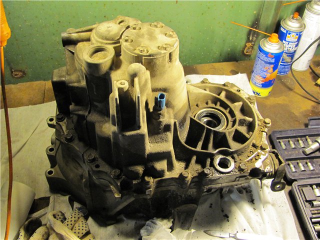
We clean it from dust and dirt and unscrew a couple of dozen bolts. In order not to suffer much, I used an electric screwdriver.
Next, you need to remove from the sealant. Used a caliper spreader. Fortunately, there are places specially designed for this. Eventually:
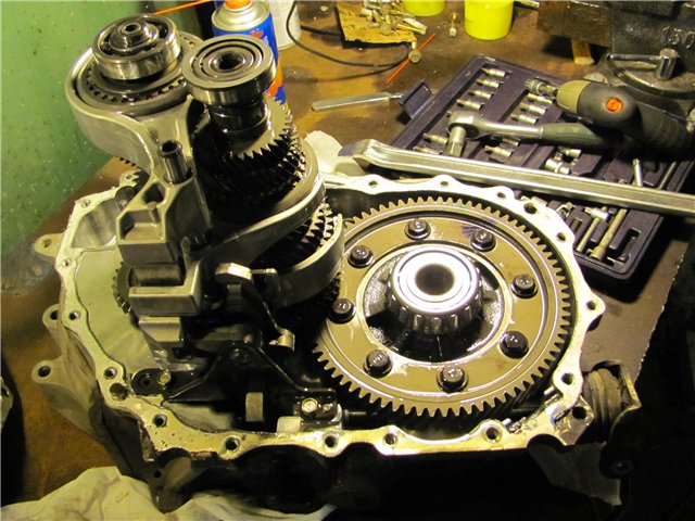
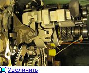
We unscrew, take out the switching mechanism. Remove the shaft from the reverse gear and see one TORX.
Was purchased in advance for 120 rubles. there is a set of keys in HyperGlobus. We put on the pipe and unscrew it. Because keys are usually very short.
The shafts can now be removed.
We knock out the pins (pins are needed) and
with a two-armed puller, remove the bracket from the gearbox rod:
Next, we actually change the thrust, the oil seal.
We pass to the input shaft. We remove the bearings and the synchronizer hub:
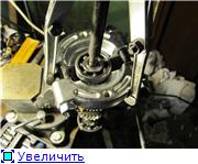
as a result, we get access to the roller bearing:
As a respite, I took up the filler plug. The hex was ripped off in the summer when the clutch was replaced. Finally, there is an opportunity to solve the problem. Attempts to unscrew it through tightening the bolt from the inside did not lead to anything. Tears the thread. As a result, I drilled a hole up to 13 mm and made two cuts with a hacksaw:
then a couple of blows through the drift and the plug is turned inside out. Traces remain, but it's not scary:
We are starting to deal with the outer races of roller bearings. They sit in the halves of the crankcase. The manual says that a special puller is needed to remove the latter. Having slightly twisted this thing in my hands, I took a two-legged puller and with a grinder reduced the height of the protrusions for engagement and gave it a semicircular shape. I turned the protrusions outward. In the end, everything went like clockwork:
In the other half, I had to choose where to rely on:
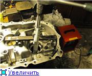
With the segments of the differential bearings sorted out. Only one segment of the secondary shaft bearing remains. This put me in a slight stupor. There is nowhere to hook on from below. Oiler interferes. Fortunately, there is a new one in stock. Resolved. We pick out the plastic and get two millimeters that way. But the trouble is, the middle two-legged puller simply does not fit there. A small puller for the bearing of a VAZ generator, bought once, came to the rescue. We unfold the stripper legs outward. Let's try. Tolstish.Remembering the grinder. We give the desired shape. Eventually:
Installing new outer clips:
Here I used a VAZ 2108 hub bearing puller and an old slice as a mandrel.
Moving on to the inner parts of the differential roller bearings. I tried it with three paws, it tears the bearing. As a result, it was decided to disassemble the bearings and make a groove in the residual inner cage with a grinder. Case of five minutes:
the fit is very tight, but in the end it went:
This is what the removed part looks like:
We install new internal parts using a hammer and a suitable head. We do not confuse the places of the external and internal parts of different sets of bearings.
We pass to the most difficult part - the secondary shaft.
We remove the roller bearings.
Next, remove the 5th gear of the secondary shaft. We use a special groove:
Further, the hub of the synchronizer
So we reach the last hub. Behind which, in theory, there should be a second roller bearing:
Doesn't go. The stripper breaks down. Distance too small for engagement. With a little thought, it was decided to clamp the hub through wooden spacers in a vice and knock out through the head. The main thing is to move at least 2 mm. As a result, we succeeded in this. Then again with three paws and went.
As a result, we have a bunch of interesting details arranged in the order of removal:
and we get a lovely view of the first gear roller:
Note that measuring the thickness of the old and new rollers with a micrometer did not reveal any differences. Strange, but true.
We assemble back using a hammer and a steel pipe as a spacer. The latter was bought by the household. store for 35 p. I bought the pipe in advance with a larger input shaft bearing along the inner circle as a sample.
To check the tightness, we temporarily assemble a box and use a depth gauge:
As mandrels for shaft seals, we use the inner races of the old differential bearings.
Taking this opportunity, we change the bushing on the clutch lever:
If you need to play in one when installing the manual transmission in place, you need to file the stool to the required height and wrap the box with suitable clothes. Otherwise, there is nothing to tackle. We stand to the right front wheel, pull up the box and with the left foot sharply move the stool under the box. I wonder how it looks from the outside?
Afterword:
1.) Of the entire system, the largest wear appears to be in the differential gears (38425-01M05). I had to take it in advance.
2.) Subjectively, the bearings are in good condition
3.) Did four days. The day began in the afternoon. I tried not to rush.
4.) For some reason, 3 bottles of oil were not enough. Ambush.
5.) Better to do it together, if possible.
6.) The most difficult is the last hub of the output shaft synchronizer. In theory, it needs to be changed.
7.) The easiest is to go wrong
Since 2006, the NISSAN auto concern has been producing the budget car Nissan Almera Classic B10 with a manual transmission. This vehicle is distinguished by its simplicity and low-cost maintenance. Each car requires regular maintenance, but many car owners neglect this and do not regularly change the oil in the gearbox, which significantly reduces the service life of the Nissan Almera Classic gearbox. Therefore, in Nissan cars with a manual transmission, this is one of the weak points. To maximize the service life of the Nissan Almera Classic gearbox, you need to regularly change the gear oil and make manual transmission diagnostics.
Our auto technical center specializes in repair and diagnostics of Nissan Almera Classic gearboxes. You can do manual transmission diagnostics with us and change the oil in the gearbox. We only stock original spare parts for the repair of Nissan gearboxes and transmission oils. Always in stock used contract transmissions for Nissan Almera Classic. If you still have a broken gearbox on the Almera Classic, call and sign up for a free gearbox diagnostics. We will repair your car as soon as possible.We have everything for the repair of Nissan Almera Classic gearboxes.
One of the most common malfunctions of the Nissan Almera Classic box is the breakdown of the fifth gear (crashes) when turned on. The reason for this is the incorrect operation of the Nissan gearbox. The main rule of correct operation of the manual transmission is not to accelerate in fifth gear from low speeds. This puts a heavy load on the fifth gear of the box and quickly leads to damage to the lead splines of the gear (see photo). Correct operation of the box: after reaching a speed of more than 100 km / h, when overtaking maneuver, turn on the fourth gear of the manual transmission. In order for the Nissan Almera Classic gearbox to last as long as possible, you need to regularly change the gear oil in the manual transmission and make timely diagnostics of the gearbox.
At the heart of the fifth gear repair is the availability of spare parts. In our service for the repair of manual transmissions, spare parts for the repair of Nissan Almera Classic gearboxes are always available. You do not need to waste time looking for and waiting for spare parts for the box. Within one day we will carry out diagnostics and inexpensively repair the box. The first symptoms of a breakdown of the fifth gear are the backlash of the speed knob when the gear is engaged. If you have these symptoms. You need to call the master and sign up for a free diagnosis of the Nissan Almera Classic gearbox.
The cost of repairing the Nissan Almera gearbox (as well as Almera Classic), excluding the removal and installation of manual transmission, is from 6000 rubles. The cost of repairing the checkpoint, taking into account the removal and installation - from 11,000 rubles. The prices for spare parts are fixed when ordering them.
We have been specializing in the repair of gearboxes for many years, and we guarantee a solution to any problems with the gearbox. Nissan Almera gearboxes of any modifications are accepted for repair:
- Nissan Almera (N15) 1995-2000
- Nissan Almera (N16) 2000-2006
- Nissan Almera Tino 2000-2006
- Nissan Almera Classic (B10) 2006-2013
You can buy from us (if available in the warehouse) or order any spare parts for the repair of the Nissan Almera gearbox, including the Nissan Almera Classic, as well as manual transmissions for complete replacement. To order and clarify the price, let us know the VIN number of the car. We draw your attention to the fact that the sale of manual transmissions and spare parts is carried out only during repairs with us!
Cars of the Japanese concern Nissan are very popular among domestic car owners. They have proven themselves well on Russian roads, are distinguished by their reliability and high performance, comfort and stylish design. All this fully applies to the Nissan Almera N16 model, which is quite in demand in the domestic automotive market.
Subject to timely service and compliance with the manufacturer's recommendations for the operating mode, the owner of such a car will not need serious repairs for a long time.
However, sooner or later, such a need may arise, and in this case, it is recommended to entrust the repair of the Nissan Almera N16 manual transmission to the specialists of the service center. They will quickly and efficiently carry out diagnostics, accurately determine the cause of the problem and begin restoration and repair work with no less quality.
With the Nissan Almera N16, you can opt for the basic RS5F30A (4M40) five-speed manual transmission. And many make just such a choice, preferring a manual transmission (manual transmission). Despite the high quality and reliability, with a timely oil change and appropriate operation, after a few years you may still need to repair the Nissan Almera N16 QG1.5 manual transmission.
In particular, one of the conditionally weak points of the manual transmission is the support bearings of the shafts, as well as the sliding clutches of the synchronizer blocks, in which the lead-in splines of the connection wear out over time, which leads to a malfunction of the synchronizer block.
For a manual transmission, a rather typical type of repair is the replacement of the fifth gear, since often drivers misuse it: they turn on the fifth at low speeds up to 80 km / h and then accelerate on it. Since its restoration is not possible, it is referred to as consumables that require replacement with a new one when worn out.
First, repairing a manual transmission requires a range of tools and equipment, from a hoist to a set of special (non-hex) wrenches, etc. But even if you have a sufficient arsenal of tools, the repair of such a complex mechanism requires experience and professional knowledge that an ordinary motorist simply cannot possess.
Secondly, a very important point is accurate diagnostics, and it is the service center that has modern ultra-precise equipment for its behavior. After determining the causes of malfunctions or identifying elements that have exhausted their resource, specialists begin restoration and repair work aimed at returning the initial operational characteristics of the manual transmission.
If your transmission cannot be repaired. We always have a second-hand manual transmission Nissan Almera n16. In our service you can replace the Nissan Almera N16 gearbox
Watch an interesting video on this topic

