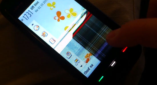
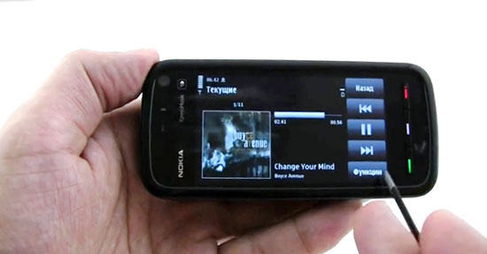
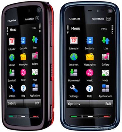
Immediately after the first batches of Nokia 5800 phones fell into the hands of their owners, complaints about incorrect display operation in this model became more frequent. After unlocking the keyboard, stripes (vertical or horizontal) appeared on the screen, which made it impossible to further use the device, given that the phone is touch-sensitive, and even its keyboard is displayed on the screen.
Immediately after the first batches of Nokia 5800 phones fell into the hands of their owners, complaints about incorrect display operation in this model became more frequent. After unlocking the keyboard, stripes (vertical or horizontal) appeared on the screen, which made it impossible to further use the device, given that the phone is touch-sensitive, and even its keyboard is displayed on the screen.
A manufacturing defect was found to be the cause of these problems. All attempts to fix the problem did not bring results (or it was short-lived). Later, all workshops and service centers that repair Nokia phones came to the conclusion that this problem disappears only with a complete replacement of the smartphone display.
A similar procedure is also necessary in case of damage to the matrix, when the following "symptoms" occur: complete or partial absence of an image, "streaks", cracks, spots and other interference. All of these problems concern the screen itself (not to be confused with the touch glass). If you have some skills, tools and parts (in fact, you need a new display), you can easily change a failed part.
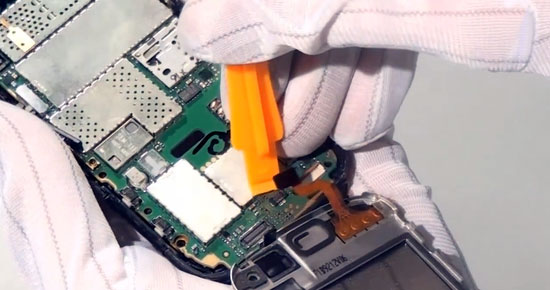
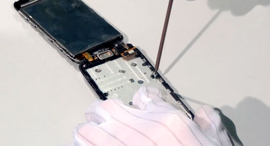
Before starting work, remove the memory card, SIM card and battery. Then check for the presence of such tools: tweezers, a T5 Phillips screwdriver, a pick (craftsmen use an ordinary bank plastic card instead). After removing the back cover, four bolts will be visible along the edges, which must be unscrewed and removed with tweezers.
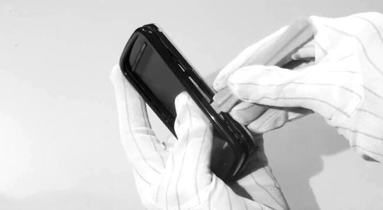
Next, we disconnect the panels with a pick along the side seams.
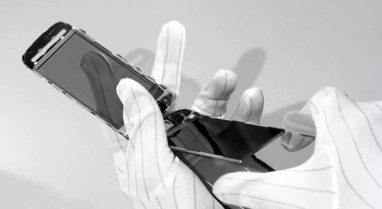
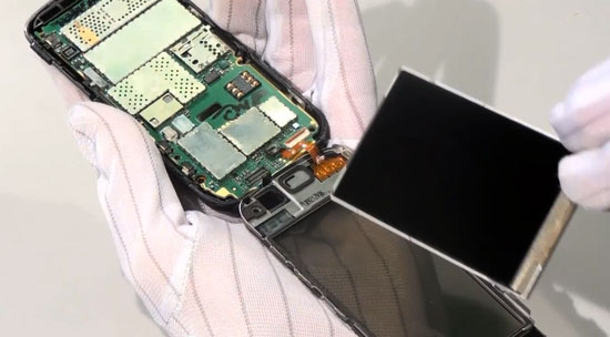
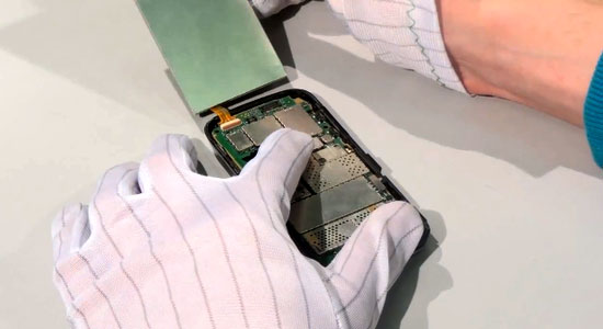
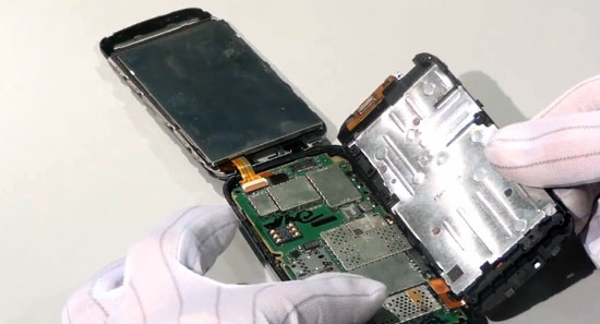
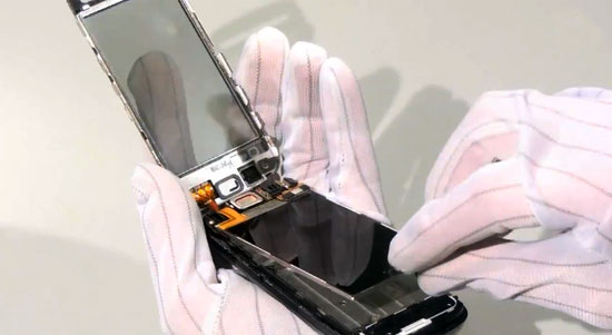
The use of special devices eliminates mechanical damage to the body parts. Remember: the top and bottom panels are connected by a cable, and our task is not to damage it during disassembly. After detaching the top of the lid, the display is practically accessible. In order to remove it, fold back the touch panel, release the cable from under the metal cover, having previously unscrewed two more bolts on its sides.
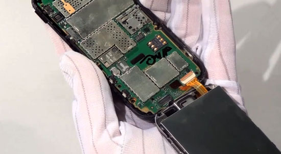
The main board is located immediately below it, so be extremely careful at this stage.
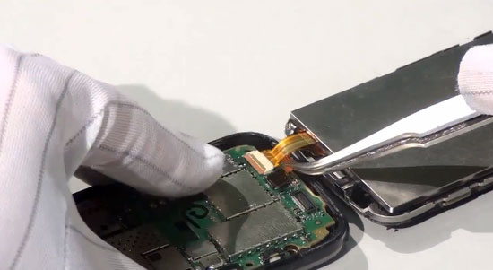
When removing the cover for a while, remember which side it was attached to inside. After we have bent the base of the cable out of the corresponding connector, you can completely remove the damaged display from the phone. This must be done carefully, without pressing hard. Keep in mind that initially the part is glued to the base, but not very tightly.
The main part of the work is behind, it remains to return everything to its place in the reverse order. So, first we insert the base of the cables into the newly freed connector.
Then we put the metal cover in place and secure it with two bolts. Closer to the upper left corner of the case, we restore the connecting cable between the front and rear parts of the case.
After replacing the screen and before the complete assembly, you should check its operability, and only if it is turned on correctly, complete the assembly. Of course, Nokia has already fixed this defect, but this instruction can be useful simply when disassembling the phone, or if you need to replace the screen.
Smartphone owners with electronics skills will have no difficulty in eliminating the screen defect on their own.This is much easier to do than, for example, replacing the display for a laptop or tablet. On the other hand, even if you are confident in your abilities, it will be safer to contact a workshop for help. So you will have insurance in case of breakdowns during the repair process or even a guarantee for new parts (from 30 days or more).
You can download movies, clips, episodes, trailers for free, and you do not need to visit the Youtube site itself.
Download and watch an ocean of endless video in high quality. Everything is free and without registration!
6) Using tweezers, remove the phone lock button, it may fall out by itself when you removed the frame, this is normal.
14) Insert a plastic card between the case and the display of the phone and gently lift the display to remove it
26) If you need to replace the charging connector, you can get it with the charger plug
27) Using a dental instrument, we remove the speaker, if it is necessary to replace it, the phone has two speakers
Phone disassembly is complete.
This is a translation of Nokia's official Nokia 5800 Xpress Music disassembly guide.
VIDEO
This DIY Nokia 5800 XpressMusic disassembly video provides detailed step-by-step instructions to help you repair the phone yourself. With this video, you can repair your cell phone, display and touch screen yourself. Also, following the video analysis of the phone, you can replace the speakers and microphone with your own hands. In addition, the video instructions give recommendations on how to repair the battery and fix the phone's cable.
Fast delivery of inexpensive original spare parts for the Nokia 5800 XpressMusic cell phone in Moscow and other regions of Russia by phone - 8 (495) 125 29 79.
We disassemble the Nokia 5800 Xpress Music phone to change the matrix.
This article is not a guide to action! You are solely responsible for collecting and disassembling your device.
Remove the back cover, take out the battery, stylus, sim card and memory card. Then remove the four screws that you see. Then remove the colored frame by pulling the edges in different directions, as shown in the figure.By pulling in different directions, you will open the latches that hold the frame, after which it can be easily removed. You can use the enclosure disassembly tool by inserting it between the frame and the frame and sliding around the perimeter of the frame to release the latches.
It should look like this. The lock button will most likely fall out of the frame.
Remove the top case by inserting a case disassembly tool into the slot between the top and bottom of the case and sliding around to release the latches. Start opening the latches from the bottom, because from above, the upper part of the case is connected to the lower ribbon cable, which is easy to damage.
Fold the top of the case up as shown in the photo.
Remove the keyboard by prying it off with a case disassembly tool.
Insert the credit card between the case and the die and press down on the die with light force to peel it off. Then fold it up onto the top of the case.
Unscrew the two screws under the die.
Then put the matrix and the upper part of the case in their usual place and gently holding the whole structure turn the phone over. The goal is to disconnect the circled connector. The connector must be pry off with a flat screwdriver and pulled up.
Place the phone on top of the case and fold the motherboard down. Disconnect the connectors in the same way as the previous one.
The white connector is not like the others. First, lift the brown part of the connector up and then pull the ribbon out of the connector.
The motherboard is now free.
All parts of the phone are now not connected to each other and can be easily separated from each other.
Reassemble in reverse order.
If you liked it, please do not be lazy to click "I like" or "share" or "+1" just below, or post a link to the article in your blog or forum. Thank you 🙂
You can rate this article:
The article deals with typical hardware malfunctions of the Nokia 5800 XPressMusic mobile phone. General approaches to elimination of some malfunctions can also be useful when repairing other NOKIA mobile phones assembled on the BB5 platform, in particular, Nokia 5235/5230/5228 models.
The mobile phone “Nokia 5800” belongs to the 2008 model line. This device became the first smartphone from NOKIA equipped with a touch screen, which, along with good functionality and reasonable price, made it a hit of sales. The “Nokia 5800 XPressMusic” market cycle in the primary market was completed only by the beginning of 2011.
In the secondary market, the current price of the device is 3-6 thousand rubles, depending on the region and the state of the device. The main technical characteristics of the device are shown in table 1.
Table 1. Main technical characteristics of Nokia 5800 XPressMusic
Nokia Series 60 5th Edition (Symbian 9.4)
81 MB, slot for memory cards microSD (up to 16 GB)
Display resolution, pixels
Supported Cellular Networks
GSM 850/900/1800/1900, WCDMA 2100
3.2 MP camera with autofocus and flash, front camera for video calls, Bluetooth,
GPRS / EDGE / 3G, FM radio, Wi-Fi b / g, A-GPS
Li-Ion, brand BL-5J, capacity 1320 mAh
Pay attention, sometimes there are Chinese-made devices on the market, outwardly almost completely copying the design of “Nokia 5800 XPressMusic”. Moreover, some fakes are outwardly almost indistinguishable from the original due to the use of body elements, completely similar to the original model. Without disassembling the device, you can identify a fake by the appearance of the camera peephole (cheap camera modules with poor optics are installed in fakes), as well as by the user interface of the software. After disassembly, it is easier to identify the fake - the hardware platform of the fakes for “Nokia 5800 XPressMusic” is based on the logic sets of MediaTek Inc.
To disassemble the Nokia 5800 XPressMusic, you need the following tools:
1. Tweezers with curved jaws.
2. Screwdriver with TorxPlus profile # 5.
3. Tool SS-93 (paddle made of soft plastic). In its absence, you can use the "spatula" from the set of children's plasticine.
4.SRT-6 fixture (0.5 mm thick soft plastic plate). If it is absent, you can use an old SIM-card or any other plate of suitable thickness.
5. Tool SS-195, and in its absence - a flat plastic spatula 30. 35 mm wide.
Disassembly of the "Nokia 5800 XPressMusic" is performed in the following order:
1. Turn off the phone, remove the back cover, remove the battery, SIM card and memory card.
2. Unscrew the 4 TorxPlus # 5 screws holding the middle case panel (Fig. 1a).
3. Using the SS-93 tool, unhook the latches holding the middle panel of the phone case, and, lifting it up, remove it (Fig. 1b).
4. Using tweezers, remove the plastic cover of the side phone lock key (Fig. 1c).
5. Using the SS-93 tool, disengage the latches holding the front panel of the case and remove it (Fig. 1c).
6. Lift up the touch panel of the phone, starting from the bottom of the device (where the end and call keys and the menu key are located). To avoid breaking the interface cable of the touch panel, you should not lift its upper part (Fig. 1d).
7. Remove the overlay of the keys located on the front panel (send and end a call, call the menu).
8. Using the SS-195 tool, carefully pry the display, starting from the side of the front panel keys (Fig. 1d).
9. Gradually introducing the SS-195 device, release the phone display from the adhesive base holding it on the middle panel of the phone, and then lift it up, starting from the bottom side (where the front panel keys are located).
10. Unscrew the 2 TorxPlus # 5 screws holding the back of the phone case base (Fig. 1e).
11. Place the display and touch panel in place, flip the phone 180 degrees, and remove the back of the phone base (Figure 1f). At this stage, it is possible to replace the polyphonic speakers, charger socket and other elements located on the back of the base of the phone case.
12. Disconnect the keyboard panel connector from the telephone system board (Fig. 1g).
13. Lift the system board and disconnect the flex ribbon interface connectors located on the middle of the phone base, display, and touch pad.
Note. To avoid damage to the interface loops, disconnect the interface connectors in the specified sequence. (Fig. 1h).
14. Remove the phone system board, display, and touch panel.
15. If it is necessary to replace the cable glued to the middle part of the base of the case, carefully release it from the latches and adhesive base (Fig. 1i).
16. To replace the earpiece, first remove the metal bracket that holds it.
17. If it is necessary to replace the camera module, carefully remove it from the motherboard slot; in this case, it is recommended to use a special bracket that allows you to simultaneously open all the latches holding the camera module;
Rice. 1. Procedure for disassembling the phone
The assembly of the device is carried out in the reverse order.
Generalized Troubleshooting Technique
1. Connect the phone to a power supply unit with a built-in ammeter and measure the current consumption (input voltage of the unit is 4.2 V). For a working Nokia 5800 phone, the off-state consumption should not exceed 3 mA. An increased consumption, not exceeding 30.40 mA, may indicate the presence of oxides that create parasitic electrical circuits, and a higher consumption may indicate a malfunction of the telephone elements.
2. If the phone does not turn on, check the serviceability of the power on key, for which the phone is connected to the power supply unit and the presence of an increase in the current consumption up to 70.100 mA when the power key is pressed. Please note that NOKIA phone batteries are equipped with a 3-pin connector, the location and pin assignment of which is shown in Table 2.
Table 2. Purpose of contacts of the BL-5J rechargeable battery
Battery Size Indicator
Battery output voltage
The BSI contact serves to indirectly determine the battery capacity and monitor its temperature. The BSI contact is structurally the midpoint of a resistive voltage divider connected between the GND and VBAT pins. Temperature monitoring is achieved by using a thermistor divider in one of the arms. On the Nokia 5800 XPressMusic phone, the BSI battery pin is directly connected to the L11 pin on the N2200 power controller. Thus, without a BSI signal, the phone will not turn on, however, when you press the power key, you will still observe a short-term increase in current consumption. When the phone is being repaired, it must be powered either from a working battery or from a power source simulating a BL-5J battery.
3. If the phone does not turn on and the power button is working, connect the switched off phone to the PC and press the power key. At the same time, the messages “Nokia USB Flashing Generic” will appear in the Windows Task Manager for about 3 seconds.
4. Using the Phoenix program, the phone is tested by launching the “Selftests” of the phone in “Local mode” and “Test Mode”. The interpretation of the self-test results is shown in Table 3.
Table 3. Possible failures during phone self-test
Items "Selftests" that caused failures (test failure)
Troubleshooting tips
See “Testing Power Control Circuits”
Indicates faults in the audio path
ST SIM CLK LOOP TEST, ST_SIM_IO_CTRL_LOOP_TEST
See "SIM Slot Problems"
Phone backup battery defective
ST LPRF AUDIO LINES TEST, ST_BT_WAKEUP_TEST
Bluetooth module defective
ST CAMERA IF TEST, ST_CAMERA_AUTOFOCUS_TEST
Defective main camera module or related control circuits
Faulty front camera module or related control circuits
See “Vibrating Alerts”
See “Accelerometer malfunctions”
Light sensor defective
Here is the order of launching the Phoenix program:
1. Connect the phone to the PC.
2. Launch Phoenix and connect the phone in “Test Mode” or “Local mode” by selecting the appropriate item in the “Operating mode” drop-down list of the main Phoenix dialog box.
3. In the “Testing” item of the Phoenix main menu, select the “Self tests” item, after which the required tests are checked in the displayed dialog box (Fig. 2).
Rice. 2. Self Tests Dialog Box
4. Press the “Start” button and wait for the end of testing. The successful passing of the test is indicated by the inscription “Passed” in the column “Results” opposite the corresponding item in the list of tests, and about failures - by “Failed”.
Consideration of typical faults will be carried out in the form of step-by-step instructions, in which the transition to each next step is carried out only in the absence of positive results in the previous one. If faulty elements are found at any of the steps, they are replaced, after which the operability of the device is checked and, if the malfunction is not eliminated, proceed to the next step.
To repair the phone, you will need its schematic and wiring diagrams. In some cases, instead of replacing the corresponding ICs, it may be sufficient to dismantle them with subsequent installation, for example, soldering defects may be the cause of the phone's inoperability.
Before starting repair operations using the methods described below, a visual inspection of the telephone board (preferably under a microscope) is performed for mechanical damage and missing / damaged elements, as well as traces of liquid exposure.If such defects are found, they should be eliminated - remove oxides, replace damaged elements, restore printed conductors.
Checking Power Control Circuits
Symptom of malfunction: the phone does not turn on, or certain functions do not work.
1. Measure the current consumed by the phone. In the off state, its value should not exceed 3 mA. If the current consumption is zero, check the battery connection connector (X2070), the L2202 filter (120 Ohm / 100 MHz) and the condition of the printed wires connecting the battery to the N2200 power controller. If the current consumed in the off state exceeds 200 mA, the board is monitored for the presence of very hot components and short circuits.
2. Press the power key. If the current consumption does not change when you press the power button, check the serviceability of its circuits. An additional sign of a power key malfunction is the phone's reaction to the charger connection - a short beep and an indication on the display.
3. Check the presence of voltages at the test points of the main board (see table 4). In the absence of one of the main voltages, first check the serviceability of the external piping elements of the corresponding circuit, and then replace the corresponding converter.
Table 4. Main voltages of Nokia 5800 XPressMusic
Do you have experience in disassembling a smartphone?
Nokia 5530 disassembly
This manual has been written based on my own experience. I tried to explain everything in as much detail as possible and draw the reader's attention to the "pitfalls" and features of the smartphone that are not mentioned in other articles or video reviews. The instructions are useful for those who want to change the case, replace the touch panel, etc. Naturally, everything that you will do is done at your own peril and risk, and the purpose of the instructions is only to facilitate your work. Good luck!
Step 1 Preparation
Begin:
Step 2 Removing the front bezel.
In the illustration with numbers from 1 before 9 the places in which the edging latches are located are marked. The areas where the plumes pass are marked in red.
1. To remove the edging, insert the pick into the gap in the area between the latches. 1 and 2 (the most convenient and safest place). 1 when the latch 1 jump off we go down and open the latches 2 , 3 , and 4 - the lower part of the edging must come off. 5 on 9 .
In the following image, you can see the latches (1 –9 ). In numbers 10 , 11 and 12 the guides are indicated (they do not cling but fix the edging). Unlucky number 13 one of the same trains is indicated (to calm me down, I will say that I had no problems). When removing the edging, you may hear a quiet crackle - do not be alarmed - this is the silicone seal (14 )
Step 3 Removing the touch pad 1 –5 ), and its train runs at the upper left corner.
We start to shoot from the right side by inserting the needle along the trajectory 7 and bend the ear outward. We start with the first staple, then the staple 2 , 3 , 5 and 4 - priority sequence. By digit 9 the screen is marked - it must be sealed with cling film so as not to get dirty. 1 (see next figure). In the same way, we bend the scarf of buttons along the trajectory 6 (it rests on two protrusions.
Throwing back the touchscreen, we can enjoy the view of four 7 (of six) bolts. Take an asterisk for 6 and unscrew it (you can unscrew it later). You can also see the flat cable and headphone jack (4 ), touchscreen loop (5 ) and a loop of volume keys and something else (3 .)
Step 4 Removing the screen 2 ... To remove the display, insert the needle along the trajectory 1 and pry the display up (you will hear the crackle of a sticky tape - do not be alarmed!). In the area of 3 the cable of the screen and its socket are laid. Bend the display 90 degrees along the trajectory 1 ... Holding the screen with one hand - disconnect the cable with the other.
To do this, prying from below, bend the brown retainer 8 along the trajectory 4 . 7 from the nest along the trajectory 6 ... I did not take more detailed photos - my hands were busy and everything was just there.
Step 5 Disassemble the middle chassis 1 ). We contemplate the same scotch tape (2 ) and screws (3 ) - unscrew them with an asterisk four.
When all the screws are unscrewed, we pry the middle part of the case and bend it down (trajectory 4 ). If you have removed the scarf with buttons, it will be more convenient to bend it up.
Step 6 Disable loops
Plume 4 we turned it off when we removed the middle part of the case - not as difficult as it might seem. It will be even easier to put in place. Disconnect the loop 6 and leave it hanging out - we haven't removed the headphone jack yet. We also carefully disconnect the touch panel cable. 5 .
Step 7 Removing the system board
And of course the packaging! It is able to protect food from dirt and preserve its taste.
Step 8 Removing the middle chassis 2 ). One of the two speakers (3 ), microphone (4 ), two loops, touch keys and every little thing like meshes and seals. Since this part of the case is not visible in any way, I advise you to leave it when changing the case. So you will save time by rearranging everything described above (except for small things) to a new panel (1 )
After removing the middle panel, all that remains is to remove the headphone and charger jacks from the back panel. This is done simply - insert the appropriate plug and push the socket up.
Step 9 Disassemble the rear of the chassis 7 ). Let's start with the antenna. It rests on four latches (1 –4 ) and the whole difficulty of disassembling is to notice them. They are located in the designated places - we pry them with a needle and squeeze them slightly. When all four latches are removed, we squeeze out the panel along the trajectory 6 .
Now we remove the speaker. This is not so easy and is done in the same way as in the case of the display - prying with a needle.
ALL! Congratulations! The phone is disassembled and ready to change. If you were careful and strictly followed the instructions, the chance of damaging the smart is minimal.
___________________________________________________________________________________________________
Everyone and everyone. |
Nokia phones are beautiful, reliable, feature rich and high quality. Many believe that they cannot be broken, smashed or harmed. In many situations, where ordinary phones, communicators and smartphones break down, Nokia phones come out dry. There is some truth in this, although not completely. By the way, let's talk about water, how it affects the operation of the phone and whether there is life after, using the example of the modern model Nokia 5800.
Anything can happen to telephones - they are broken, smashed, they fall into the water or get caught in the rain. In general, they do everything to make it a necessary part of the possession of the apparatus. And, as if simple tests of the phone are not enough, many users then also try to "treat" their phone on their own. I got into the water, what should I do? Online advice is full of conflicting opinions, from rinsing with alcohol to drying with a battery or hair dryer. What can really help?
First you need to figure out what exactly does water harm to your Nokia 5800. Water is such a harmless substance. Right, harmless. Until it interacts with the battery, causing electrochemical corrosion of the board. That is, in other words, water begins the process of oxidation of the elements of the phone, which will inevitably lead to rust and damage. Not a very pleasant prospect. Moreover, even if you repair the nokia 5800 at home, disassemble the phone and dry all the elements, try to process the circuits, this will not give a full guarantee that you will eliminate all the water and after a while the corrosion will not make itself felt. Remember: the longer the process of oxidation and destruction lasts, the more expensive it will cost you to repair it in the future, and it may not be possible to save the phone at all.
The first thing you will need to do after your phone is in the water is to remove the battery, and the faster the better. Then the corrosion process can be stopped or at least slowed down. Do not try to let the battery dry out yourself, and then try to turn on the phone again! Getting into the phone with water is a serious matter, so it would be most reasonable to give the phone directly to the repair of a Nokia in Moscow, if, of course, you live in the capital.
Professional craftsmen will be able to carefully disassemble the phone, complete deep cleaning in an ultrasonic bath, mechanical cleaning and complete drying of your device, and if necessary, remove corrosion from parts, and in advanced cases, change parts of the phone. After repairs, the unit will be professionally tested for residual problems. None of this can be achieved at home.
Video (click to play).
Many experts say that phones with various dysfunctions that have arisen, as it later turns out, from corrosion that have not been eliminated, are often brought to the repair of a Nokia in Moscow. Often this takes on such consequences that repairs become either too expensive or completely impossible. Take care of your Nokia 5800 phone in advance, and then it will serve you faithfully for years to come.

