In detail: do-it-yourself steering column cable repair from a real master for the site my.housecope.com.
This post can serve as an instruction for handy people who find themselves in a similar situation.
Although I am a radio engineer, I have been deeply involved in auto repair for a long time. There is a very decent service, where your humble servant is currently working. Well, now the story, I hope you will be interested.
Nissan Murano Z50 (photo from the Internet), our patient is not so handsome:
One smart service technician decided to replace the steering rack on his personal Murano. He did it well and quickly, but! This post would not exist if it were not for this BUT! I accidentally turned the steering wheel and forgot about it. In the steering wheel there is a long train wound in a spiral in order to transmit electrical signals to the steering wheel itself. I think for many of you this is obvious. I assembled, started, pumped the system - there is no beep, an error on the pillow is on, the multifunction wheel does not work. All clear. Tovarisch sighed and called me to save the day. Tool in the teeth and go!
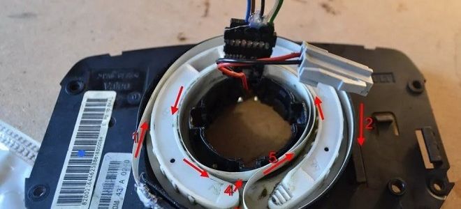
Got it out, dismantle it, it's late, I'm taking the subject home. (my daughter is 4 months old, so I apologize for the extra objects in the frame) Here is a snail:
And here is what gave a turn of the steering wheel one turn more (I cut off the mantle piece of the train, but he has a photo):
Naturally, the train itself inside was twisted and re-bent. Straightened up, rang. the roads are intact. Let's get started! We prepare the train and the receiving part, clean everything. And yes, without a third hand in any way.
My visit to the service today only added a headache. When everything was ready and when I was leaving, I turned the steering wheel, it turned unexpectedly easily and, having made a few turns very easily, stopped, a distinct “click!” Came from the steering wheel.
I will not describe all those expressions that rushed through my head towards the “masters” who have already messed up before, the topic is not about that.
| Video (click to play). |
In the steering wheel, the steering column cable came off. The one who is responsible for the "BBC", airbag and radio tape recorder control.
Of course, the original could be ordered, here is its code: B01A-66-CS0. But 14 thousand for a box with a train of 40cm is not ours as it is)
For treatment we need (in addition to keys for dismantling):
- Soldering iron
- Small flat screwdriver
- Stationery knife (blade)
- A tester for the final call is desirable.
We open and remove the steering wheel (There are no such photos, I will probably add it tomorrow when I put it back), disconnect the chips and get such a bagel
Latches shine deceptively around the perimeter - snap it off and it will open. but it was not there.
First, we look at the center of the donut. There is such an inconspicuous bearing with latches inside.
We unfasten them with a flat screwdriver, while it is convenient to squeeze it out with your fingers pressing on two protrusions.
There we have a view to the inner place of the loop attachment.
And the “bearing” itself can be installed in only one position, for this two slots are made on it.
And here is the hero of the occasion. And a tambourine. well that is inner disc with rollers.
Alas, the location of the train in the state between the rollers is not necessary to observe after a break, therefore we look carefully at the rollers.
The yellow video clearly stands out for a reason, I think that it serves as a mark when setting the center through the window (seen in the first photo on the left), but after today all these marks are worth little. Therefore, we look at the upper right part and see an obvious place for the release of the train. So we remember.
Now we go to the place of the cliff.
I had it near the connectors. As you can see, a piece of the cable remained clamped under the contacts.
We pry the white part with a screwdriver to lift it entirely, turn it over and see the train.
Before that, the black plate was hiding in the slot of the “donut” body. In the photo above, only two black points of its attachment are visible.
It is used as a clamp for the cable and does not snap into place, but is pulled out as shown by the arrows in the photo.
As you can see, the clamp is strong enough, because the train burst before it came off the contacts.
They freed and threw away the stub.
As you can see on the loop, the two tracks are noticeably wider. This is very convenient because will not allow you to confuse the sides.
We cut the remaining part evenly (as little as possible, and if the break is far from the edge of the loop, then it is better to solder the loop together by cleaning the contacts on both parts, solder them and glue them with good tape).
So. Next, we need to clean up the contacts. This will require a clerical knife (blade), a screwdriver and nerves of iron.
I killed about 4cm of the train while I was able to properly clean this freaking train without breaking its veins. Especially narrow.
According to the "rules", you first need to carefully scrape the coating with a blade at an acute (.) Angle (I scraped the "end" of the blade, it would be more correct to say I held the blade and pulled the train under it) and when it is already thinner, copper gaps will begin to appear, use a flat screwdriver to clean the contacts ... This must be done from both sides.
Cars change, friends and the forum remain. [my.housecope.com/wp-content/uploads/ext/1209]
Message Vitox »27 Nov 2013, 22:38
If you pull out a chip, it first closes the contacts among themselves. So it is not necessary to turn off the battery, although everyone here decides for himself.
It is very easy to set it to the center position. One of the cage rollers is yellow. Seen from above, there is a transparent window on the left. In the center position, only the yellow roller is visible there.
Check how everything turns. I got two and a half turns in each direction.
Can be put in place.
Nice savings for one evening.
Who knows how to solder and use a multimeter, the operation is simple. Or give it to any cell phone repair, I think they will solder four wires for inexpensively.


Message SkiF 54 »27 Nov 2013, 23:01
Message Vitox »29 Nov 2013, 06:49
Message Ram_maR »29 Nov 2013, 06:55
Message Vitox »29 Nov 2013, 11:57
Message megafon_35 "Dec 16, 2013 09:04 am
Vitox,
interesting approach. I have already encountered the installation of the KK, but on the German - Opel Zafira A (Subaru Trivik), but there I had to lay 3 wires from the brains to the steering wheel and solder to the brain leads, the main thing is to know the information about the contacts.
the principle and analogy of these motors are identical, that is, electronic damper control.
in the German everything was laid down initially, but it was necessary to know what and where to connect, there was no need to flash anything.
the issue price for me was resolved in just a couple of hundred: 10m. wires - 50-70 rubles, I don't remember anymore, the toggle switch (button) is activated for 12V. can be done with highlighting and 2 touch buttons “+” and “-“.
the officials of this service cost 8t.rub.
I think that Toyota has a similar situation. you just need to call the correct contacts, tk. all paddle switches are nothing more than mechanical commutation, but to check it is necessary to deal with this issue. until the hands and head came to this.
Vitox,
you didn't even have to strain very much and replace the train from everything from the steering wheel to the chip.
Added after 23 minutes 52 seconds:
here is a photo: green activation button, and white-gray on the steering column “-“, on the other side “+”
Steering column train. Repair. Chaser JZX100.
I just complained here that the front airbags malfunction light came on, and then the bibikalka died. He took off the steering wheel, looked, all the wires are normal - it means the train.
- Hello, hello, is there a steering column train for the hundredth chayzer?
- Yes - a ruble.
- Thank you.
***
- Hello, hello, is there a steering column train for the hundredth chayzer?
- Let's see. yeah there is - a thousand.
- Thank you.
***
- Hi, this is Anton, do you have a stalk for the hundredth kettle there?
- Yes, of course, for you for a thousand.
- OK thanks.
I myself think, what is a popular spare part that would sell it for a ruble? And during the first troubleshooting, I opened the body of the train, like a niche special, a coiled train. The principle of operation is elementary. Most likely a break in the loop is 99%. And here's a gimmick. I would think about the pizza, then ruble.In the evening, having previously armed with the necessary things: a flat thin screwdriver is enough, a soldering iron + rosin + soldering acid, an electric tester, an anti-silicone (I wipe everything with it), with an ordinary wide tape, I started repairing:
[it was already about removing the steering wheel, but for completeness of the topic it is present here]
And so, turn off the battery. For each of both terminals (although I connected the seats when I threw off only a minus, nothing bummed). As I read in some topic - I waited 15 minutes. They say that during this time all onboard systems are de-energized. And I started with the steering wheel.
Again, with a flat thin screwdriver, carefully “rip off” these plugs. There are two of them. One on each side.
Behind the plugs we see bolts with an "asterisk" on the cap.
They are unscrewed with a nozzle marked T30:
After the bolts are unscrewed, they remain in the seats. They are unobtrusively held there by plastic, small ones bent with the letter "G". The first time, for a long time and stubbornly, I gouged it out with a flat small screwdriver again, or rather two, the second time I jerked and just gently wringing this nozzle with an asterisk when it was inserted into the bolt and twisting at the same time easily removed them from anywhere. After that, the pillow is carefully pulled out of its rookery, and what do we see there:
The left arrow points to the power supply of the pillow itself, open the "cunning" latch (everything is intuitive there), and pull out the plug like all similar plugs in the car. They are all different in shape, but the principle is the same: press on the clamp - pull it out. And remove the pillow. Having previously screwed into it the bolts with a star, so that they would not get lost. The right arrow points to the white plug, which is responsible for "beeping", we pull it out too, it will be removed from the steering wheel. We unscrew the nut, circled by the head at 19, not completely, as it is advised everywhere, we leave it on so that when pulling off the steering wheel we do not get the steering wheel in the nose and heart-rendingly trying to remove the steering wheel. Tugged, tugged, tugged. My hands began to ache, I thought I got used to it all, then I pulled it off somehow. I think the following helped him to “unfreeze”. Because the steering column itself walks, we pull it to the maximum, we rest against the steering wheel with our knees on the back side, and from the outside we take some kind of metal “pin” thread and a couple of times through this pin into the steering rod. On which the nut is mounted. After I took off the steering wheel. (in subsequent times, the steering wheel was removed without hemorrhage, simply with a jerk of the hands) Then we turn the nut to the end. And we mark the stock on which the steering wheel and the steering wheel sit with three marks (marker), so that we can then put the steering wheel back correctly.
And so, the steering wheel is removed:
Further, as shown in the photo, we unscrew three self-tapping screws in circles. Remove the steering column lining. The cladding is split in two and can be easily removed. The upper part has a kind of poke there, which is inserted into a metal hole. Slightly pull to the top, swinging back and forth and everything is pulled out.
[from here directly about the train]
After removing the steering column lining, we finally get access to the loop. We examine. When removing, we will interfere with two plugs, a "bibikalka" and a pillow, we pull them out, in the lower part of the loop body:
Then we unscrew 4 self-tapping screws with which the train itself is attached to the steering column:
After this simple procedure, the cable can be easily removed, the rest is a “bare” column with “levers”:
Inspection of the loop body shows that it can be opened by peeling off the lower part (on the back of the yellow sticker). Gently wielding a flat screwdriver, snap off all the small latches (the red arrow points to one of them, there are several of them in a circle). Then, in the place where the wires from the steering column are connected to the loop, there are two soldered fasteners (red circles), we break them off with a little effort. Copus opened:
Disconnect all the components of the loop:
1. Top cover with a wire for the pillow, a plug for the "bibikalku" and the actual cable itself twisted into a "snail"
2. Loop body.
3.Gasket, between the ribbon cable and the bottom cover.
4. Bottom cover, with plugs for wires coming from the steering column.
In the place where the train grows into the top cover, there is plastic, which apparently plays a role, emmm crap, which does not give the train of sminazz to the accordion. Running into the front I will say that I had a cliff just in that place. The plate had to be removed. To do this, carefully break off two clips with a screwdriver:
They will allow you to remove the plastic marked with an arrow. And to get access to the "accordion" (in magnification), the palubas is cut off there:
Expand the train. Accordion. Apparently, when at the beginning of winter they made me toe-in after replacing the steering and lower front left levers, I asked to symmetrically set the steering. The steering wheel was 90 degrees to the right. And I rolled it for two days, apparently the result is an accordion on the train.
... and tochnyak, on one of the folds of the accordion - a break. And the Trail is covered in some kind of special dust, similar to plastic dust:
Carefully cut the train along the fold, in which there is a break. And bite off the resulting ends by sprinkling so that they are even, then we try to remove the insulation for the solder. I tried it with a lighter, it didn't work. Copper veins quickly heat up - I did not dare to burn further.
As a result, I fused the insulation with a soldering iron a few mm from each end and with a flat screwdriver poured it off, it did not melt.
He wiped the train along the entire length with a cloth soaked in “Novol” anti-silicone. And he also wiped off all the other elements of the loop body from this dust. (I'm writing now and the thought came to my head that it was necessary to lubricate the contacting surfaces of the loop body there with a thin layer, they can rub against each other when rotating. .).
Then we take a four-thread that is not afraid of the temperature of the soldering iron and to which the solder does not stick. I took an old saucer. Be sure to use "soldering acid" - in this case - a thing! For example, in our case there are 6 cores in the loop and they are close enough to each other. If not zaparivatsa which of them are used and which are not, but just do it right, then we do not need "shorty", and lived from one end, should contact only with a similar vein from the other end, and not with the neighboring ones. This is where the "soldering acid" works wonders. We wet the contact with “soldering acid”, a heated soldering iron, a little solder on the tip of the “tip” and bluntly poke it into the contact and hold the male. The acid ensures "sticking" of the solder only to the veins, and not spreading around the circumference by closing the parallel veins to each other.
Soap dish macro photography suffers, but still:
Then we check with a needle that we haven’t made any “shorties” between the veins and check the “contact” with a tester. I stupidly put on the "ohms": the value of "adyn" - no contact (100% resistance), the value between "zero" and "adyn" - there is a contact (if you argued about the "ohms" - don't kick it, I don't really I rummage in this =), you can still use a sound piccola on the tester. squeaks - contact, does not squeak - not contact, I just junk):
All chiki-peaks, all veins are contact, there are no shorties. Then I got the idea to stir up the insulation of this type of glue, which davitsa through a gun under heating. The glue is reversible up to a heap. At the beginning, I pressed it with my fingers, then I trimmed the already applied glue with a soldering iron. It turned out like isolation:
We put in place the “white plastic” (which is curved above in the picture, in the place where the train “grows” into the lid, marked with a red arrow) and twist the train, check out what happened:
We begin to collect and find on the back side of the substrate (which is higher in the picture under the number “3”), on the side along which the train “rides” - rips:
In fact, the substrate is mm or one and a half mm thick, and it is like soft inside, like thin foam rubber, and from the outside like something polyethylene. Here I have vomited there. sat and thought for a couple of minutes. And I zaherachil with scotch tape in two layers:
... cut off the extra scotch tape along the contour and it seemed like the rules turned out =)
I assembled the cable together and melted the pins broken off when opening with a soldering iron where the plugs are:
I checked the contacts again with the tester. it turned out that the "pillows" are closed. at the beginning he was frightened. And then I saw this plate in the plug. It is factory-made, not a "snag" of the pillow sensor. Otherwise, the malfunction of the front airbags would not have burned for me, tk. the loop is already behind this plug, so that the “pillows” of the veins are duplicating.
From the morning before work, I stuck everything in place in the reverse order. The only thing is that when installing, the loop must be set in the center. The sticker says about 2.5 turns in each direction. If you turn the train that thawed in one direction, and then in the opposite direction until thawed, the mark will coincide 5 times, then we turn in some direction until thawed (without fanaticism) and rotate in the opposite direction before the mark coincides a third time: we begin to rotate - once it coincided, then we rotate - two coincided, another - three coincided - stop is exactly the center.
Dachik pillow malfunction went out, "bibikalka" works =)
I don’t remember where I wrote it and I didn’t find it already.
The problem was not only in the gap in the unknown where, but also someone decided to tear off the cable from the wires, apparently thinking that he understands there
As a result, I had to open the connecting plugs
The second side also had to disassemble the plug, since the wire was also interrupted at the very root of this internal plug
I soldered everything and inserted it filled with epoxy
Collected, checking that everything rings
(27.03.2013 21:42) Igor G320 wrote: Damn, Seryoga. I thought for a long time what to write. THANKS!
Eeeeee. nuuu - Please pick up now and install
(03/27/2013 10:36 PM) Sanya wrote: For an hour? Cool, how do you say there they say work for 5 minutes. I'll climb in and drip for an hour
Well, next time, figure out how much to multiply
Good day
so, let's begin
symptoms of failure (broken tracks due to design imperfections) cruise control does not turn on, airbag flashes, sound control
necessary things:
Contact ring steering 25567-EB60A price 4 503.13 at existential
Key 10
The flat screw is not small
Cross screwdriver
Head 19
Asterisk T25
Asterisk T10
4. We are waiting for the airbag icon to finish burning.
5. No later than 1 second after that, turn off the ignition
6. We are waiting for 3 seconds.
7. Repeat steps 3-6 3 more times.
Turn off the ignition and then start the car. Error erased.
Exchange of experience in car maintenance and repair ...
pen-a-plast Wed, 15 Oct 2014, 09:47
Good day, dear mazdavody.
As you know, we cannot do something without breaking something else along the way! In the process of removing and repairing the steering rack on my Mazda 6, through an oversight and inattention during installation, it turned out that I did such a thing as tore the same steering column cable. How do I understand that everything is broken? after installing the steering rack and docking it with the steering shaft and a test run of the car to check the operation of the rail and the result of the repair of the same rail, I was a little surprised that the sound signal stopped working, the steering wheel controls multimedia and, most importantly, the security system malfunction indicator came on. Signal and control are all nice little things, but a pillow! this is already serious! according to the results of self-diagnosis, it issued code 19 (a combination of indicator flashes - one blink, a pause of 9 blinks) which meant this
After scratching my head and taking out everything I know from it, I came to the conclusion that the problem is in the steering wheel, or rather, in the transmission of data from the steering wheel itself to the brains of the car, which confirmed my guesses first, removing it, then measuring it with a multitester of electrical conductivity and then opening it the body of this steering column cable itself.
To begin with, I'll post pictures of the process of removing this loop.for a start, you will need to remove the terminals from the battery and wait 10 minutes and, to be sure, click the near-far light switch to thoroughly drain the car and its brains. To remove, you need tools
1 Flat thin screwdriver and Phillips screwdriver
2. Head to “10” and extension
3. A head on “21” and an extension cord (if there is no such one, then a regular wheel wrench will fit this business, it is just on “21”
Then we drag all this stuff to the table and see what and how with it. I'll continue the topic a little later. There will be photos of the repair and, most importantly, of laying the train itself back as it was
Continuation of the epic - now renovation and styling
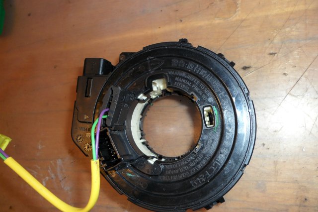
Well, actually an experimental snail
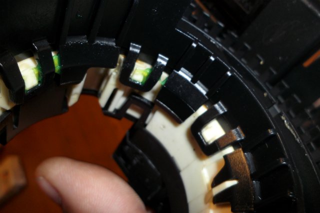

Snap off the internal fasteners
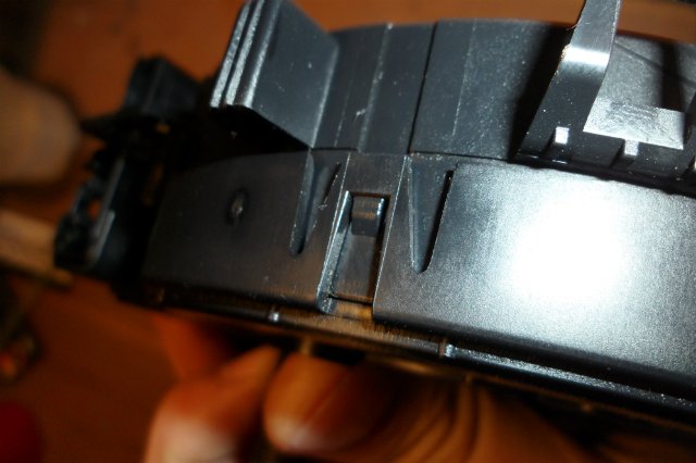

Snap off the outer fasteners
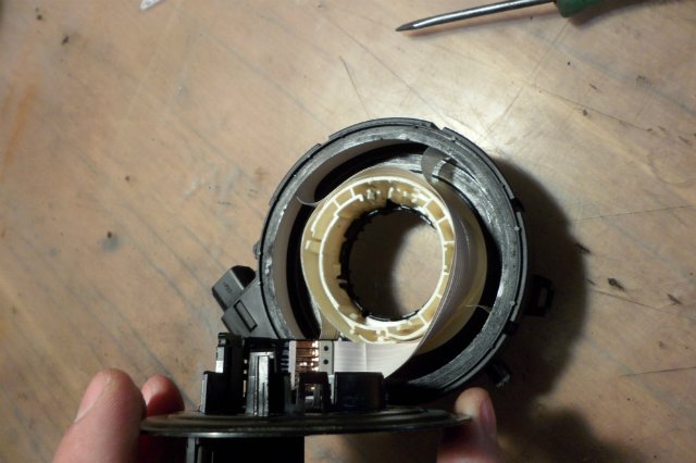
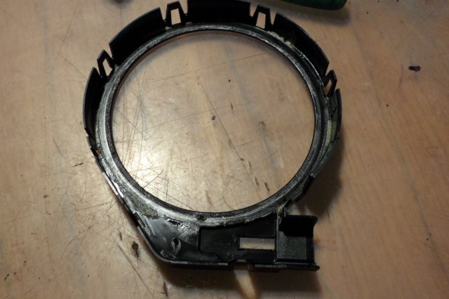
We remove all this stuff
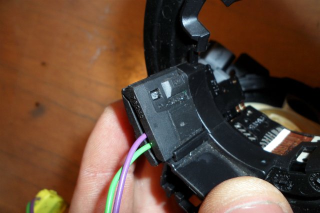

Unclip the wire retainer from the airbag
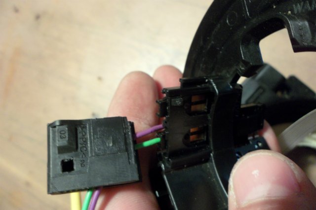

Remove the retainer
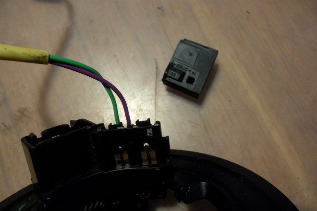

And put it aside
Remove the plug from the socket

pillow wires

disconnect them (I just tore them off) otherwise they will interfere
Remove the top cover
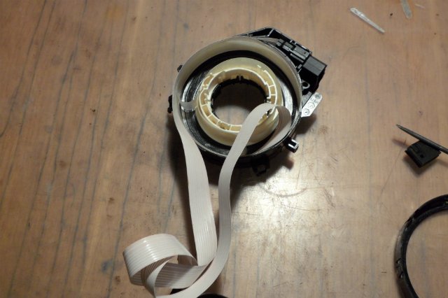

Unwinding the train
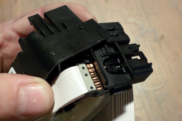

We take out the plug
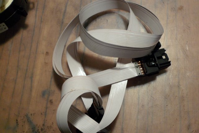

We take out the train itself completely
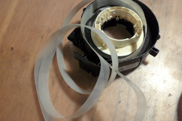

There is a transparent tape inside
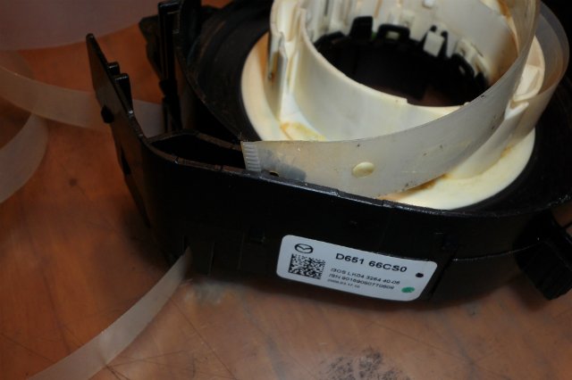

We take out from the mount
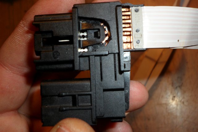

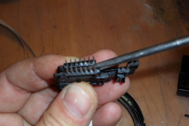
Next, we take the loop itself and disassemble the plug
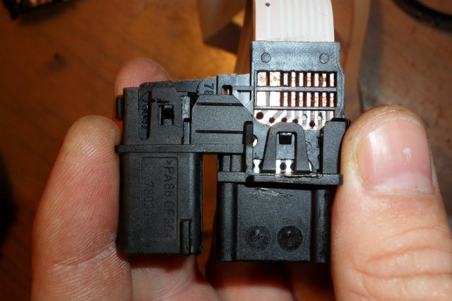
Snap off
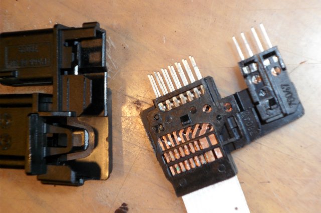

Take out

Half
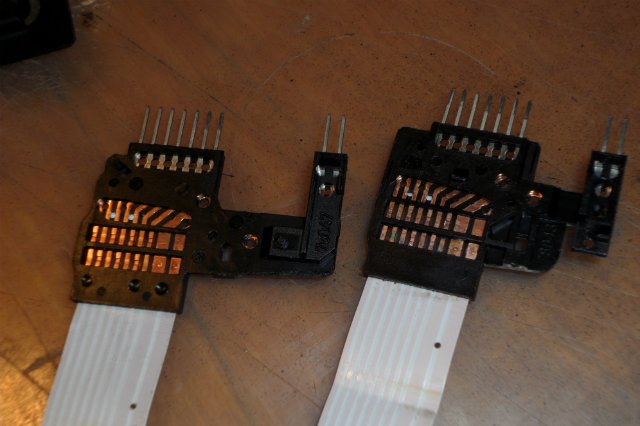

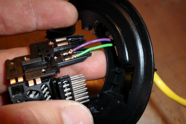
We get the following result
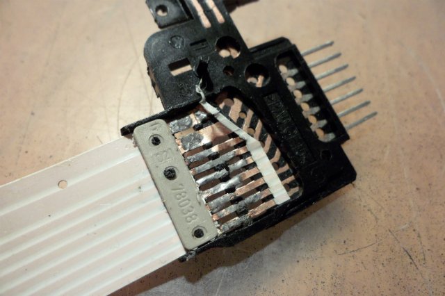

My problem was here. It depends on which direction you turned the steering wheel until a gust, then the gust may be here or on the other side of the train, since it is a short piece of this train that breaks.
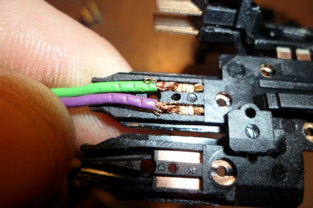
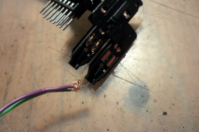
We solder everything into place (if you are not friends with the radio equipment, then in any workshop for the repair of radio equipment they will do it for you). We check the conductivity of all the tracks with a tester and if all the tracks are ringing, we proceed to the assembly
Next, we go to the car and install all the parts in reverse order. I will say one thing that I did this procedure probably 3 times to achieve the result. It all took a couple of days. then the nerve was not enough and ordered a new one (special thanks to the user -Gluck- for help in purchasing a spare part). a new one came and I still decided to try to repair the broken cable. IT WORKED the first time. tried it on the machine everything works as it should. now there is a stock just in case.
Thank you all for reading (watching) to the end.
If you have any questions, please contact me, as far as possible I will answer
pen-a-plast Honorary Mazdavod The author of this topic ... Messages: 1749 Acknowledgments: 149 pcs. Registration: Wed, 04 Sep 2013 Where: Tambov Car: Mazda6 sedan, sport,
When repairing the steering rack in American (and not only) minivans like Dodge, Chrysler, Plymouth, be careful with the steering shaft, in other brands of cars the same happens often. In the sense, do not turn it 180 degrees, during assembly and disassembly, otherwise, leaving the garage, you can break the steering cable. It breaks easily, when you turn the steering wheel you hear a click and a slight one-time wedging of the steering wheel.
Also, it can be broken by the steering train by removing the steering wheel for some reason, and without hesitation to turn the steering train. This is my case. They took off the steering wheel, twisted and twisted the inner part of the loop, watched how the dragonfly (multifunctional switch, including the turns) was triggered to turn off the turns.
Collected, I leave, I twist the steering wheel, click - then I did not understand and did not attach much importance. Even when I discovered that the signal and cruise buttons did not work, I sinned on the fuse. I checked everything is in order. Then I remembered leaving the garage, called my friend, with whom they messed up together. He works in a car service, and until the end he thought that there are circular tracks inside the steering loop housing, and contacts rub along them, transferring voltage to the steering wheel and back. It would be nice, but not so.
How not to break the steering train is clear. And now let's talk about how to save 110 $, this is the amount that was charged in several places in my city, this is for a used one. It is quite possible to repair a torn steering train. I fixed it first for myself, then for a friend who bought himself the same car, already torn.By the way, there is a difference in steering trains before and after 98, we will analyze them below.
All models of Chrysler, Dodge after 1998 release, about older versions including Plymouth I will write below, if necessary, scroll down!
Align the steering wheel. We remove the airbag, unscrew the three bolts from the back of the steering wheel, the head seems to be 8. We take out the pillow, taking out the plugs from the body of the steering loop. Then we remove the plastic casing from which the dragonfly sticks out, the steering wheel adjustment lever, and the gear selector. Three screws from the bottom, and carefully latches, I just snapped off. We take out the plugs with wires from the bottom of the steering loop. We unscrew the large nut from the steering shaft, but not completely, so that the nut moves away by five millimeters. Now you have to sweat to rip the steering wheel off the splines, it sits tight. We put our feet in space, pull the steering wheel towards ourselves with all our might, constantly shaking it in different directions. The nut was not unscrewed to the end, so that when the steering wheel breaks off, you won't break your nose. Having ripped off the steering wheel, we remove it. We unscrew two more screws from the cable and take it out.
We disassemble it, a couple of latches, a couple of self-tapping screws and you're done. We examine and see the place of the gap. In my case, it broke right at the beginning at the contact blocks, below where, about models released before 98, the option of repairing a loop that was torn almost in the middle is considered.
And here it is simpler, we cut off the torn edge of the train exactly. The veins in the train are very powerful, which also makes the work easier. I will clean the train so that the bare veins stick out by half a centimeter. Now they need to be tinned, covered with a layer of solder. A soldering iron is required to work. We dip each core in turn in rosin, or flux, we can also use soldering acid, but I do not advise copper then oxidizes strongly and the contact may be broken. The soldering iron also needs to be tinned well, for this we clean its sting until the copper is bare and the carbon deposits and shells are erased. You can clean it with sandpaper, I always whip up a file on a concrete floor. We lower the well-heated tip into the rosin, and immediately apply the solder. Now remove the rags of the loop from its body and enroll the contact group, if it fails to crawl well, scratch it with the edge of a knife and tin it. Now, adding solder from time to time, we apply it to each core of the loop, and to each contact where we will solder the cores.
We bend the train diagonally, as it was, and solder each core to its place. We put the core in place, press it with something, attach the soldering iron, when the solder melts, the core lowers, hold the soldering iron for a couple of seconds to melt the solder on the contact. We remove the soldering iron, and hold the core so that the solder solidifies, you can blow it.
Solder carefully so that each core is held tightly, and so that the solder does not come into contact with the neighboring one. After soldering, ring with a tester (multimeter) for conductivity, and for a short circuit. How they call: turn on the buzzer on the tester (when a squeak is heard when two probes are closed), touch one leg on one side of the loop with the probe, and pass all the legs on the other side of the loop with the other probe. If everything is correct, then the buzzer should beep only once, if not once - an open circuit, if not once a short circuit. Although look in one socket where the pillow is connected, there is a contactor, then call from it to the other side, opening it.
Assemble the steering train. Before installing it, twist it to one side until it stops. Mark this position, turn it all the way to the other side, counting the revolutions. You should get 6-6.5 turns. Unwind half of the revolutions back - this will be the center position of the train, because the wheels are now exactly the same. The train has a rotation reserve of six revolutions, and the steering wheel rotates from lock to lock for a total of three revolutions. If during installation it turns out that the cable needs to be turned a little - turn it, it's okay.
We put everything in the reverse order.
Chrysler, Dodge, Plymouth models manufactured before 1998.
In principle, we start the same way, remove the casing, wrap the pillow.But in this loop, the pillow does not turn off. Therefore, we throw it on its side, remove the steering wheel. The cable is on two latches, we take it out by disconnecting the wires. We turn the steering wheel over, disconnect all wires, except for the wires on the pillow. They do not turn off, and I cut them off, for further convenience, approximately in the middle. I did not dare to unsolder directly on the pillow, I saw on the Internet how they explode. We remove the body of the steering loop.
There are two rivets in the middle of the train. We grind the hats, and they can be knocked out. Then we unscrew six pieces of self-tapping screws around the circumference of the loop body, a small asterisk will be needed.
In this case, the train broke in the middle, and everything was fine with the former owner. Therefore, from time and friction, the train inside stratified. We remove the peeled film to the place where it adheres well. Align the two torn edges with scissors. Then we tinker and solder with each other.
To strengthen this place for bending, I reinforced it with a two-component polyester resin glue (repair kit for a muffler). I love this glue for its setting speed. Even during assembly, I added oil to the case, otherwise it was somehow dry. We connect the pillow with soldering, insulate well, put on a heat-shrinkable cambric for reliability. After that we call the contacts.
We unscrew the steering wheel cover, three screws. We pass the cable with wires to the pillow and fasten the casing back. We expose the train in the middle, as described above. By the way, when assembled, in order to turn the train, you need to press the stopper. They are closer to the center, like 2 or 4 you press and rotate. We collect!
Each repair took two hours. A friend is happy about the cruise and the signal is already three months old, I'm a year old.
Auto - club Peugeot - Citroen PCA - Ukrainian Forum, everything about Pyzho and Citroen, news, announcements, technical assistance, club life, meetings, holidays.
And so, one fine day, the beginning of the small (depending on the position of the steering wheel) lights up on my Peugeot and the AIR BAG FAULT error beeps. I said to Figasee, and began to think what could happen !? I came up with it, after all, 2 weeks ago I climbed into this snail and apparently did not twist the wire correctly (or put the snail) and, as a result, the bend and fracture of the tracks. As a result, the pillow knocks out an error and the signal does not work.
Well, it's not the first time for us to deal with this snail and the steering column as a whole - let's go to fix it.
We set the wheels perfectly straight.
Further:
First, we will remove the upper and lower steering wheel covers. To do this, the key is an asterisk and unscrew the two bolts in the lower casing (I recommend pulling the steering wheel towards you as much as possible)
Next, we stomp to the hood, and remove the positive terminal from the battery. (or there is, albeit not a big, but a chance to get a pillow in the nose)
We begin to remove the pillow.
We insert into the holes near the steering wheel spokes objects such as screwdrivers (I used two cross screwdrivers) and, as it were, with a little effort, we drive them inside the steering wheel.
Next, we unscrew the bolt that secures the steering wheel, and with Smooth movements, hitting the steering wheel on ourselves with our palm or fist, remove it. Look not to tear the chips, because it will not be fun, therefore, do not pull the steering wheel towards yourself too much, gently remove it. We poke the chips from the pillows into the hole of the steering wheel one by one IN the CLOSED state (otherwise you can bend it!)
Let's start removing the COM block. To do this, we need to unscrew (loosen) the tie screw on the steering head by 10.
We snap off all the chips from it and go to the house / garage / office, etc.
Next, we pull out the round crap with a spring from the steering column (we just pull strongly FOR YOURSELF (there is a maximum that can happen, this spring will move (fill the case for 2 seconds))
Unscrew a couple of screws
We put the board with levers separately (you can do it later / fix easy switching of turns or lights, etc.)
We are interested in the part with chips for the air bag.
Gently use a screwdriver to squeeze the three latches of the latch and see fucking meters of the loop. we are not afraid of pulling because he doesn’t care KAPETS


We are looking for a place where we have a break (either visually or just to call) I was “lucky” that it is an inflection and, as a result, it is almost a break.
We mark where is which side of the train with a marker. Then we cut it with scissors and begin to clean the veins. Our task is to remove polyethylene from both sides of the loop and thoroughly tin the contacts
ALWAYS call. in order to avoid shorty. One contact of the tester to the chip from the pillow, the second to the large plastic, it contains the contact outputs of this loop (twist the large plastic you will see for yourself!)
Next, we take a glue gun and apply glue to our connection, press it between the contacts with our fingers, so we repeat from one side and the other. On the sides of the train, cut off the unnecessary glue with scissors.
We put on the heat shrinkage, we heat it so that it sits down but does not squeeze the train STRONGLY.
Then I again sounded in order to avoid so to speak.
Now let's start assembling. It is performed in the reverse order (the train does not need to be cut


Let's just pay attention to the correct laying of the trail of the calamus running into the snail.
Simply, WITHOUT kinks, we wind the train on the snail drum (tightening it a little). Next, we connect the plastic of the snail together.
We remember that the steering wheel of the Peugeot 307 makes exactly 1.5 turns in either direction, respectively, we unscrew our snail by 2 or 2.5 turns counterclockwise (we need the outputs of the chips to stand strictly vertically (see the photo)
| Video (click to play). |
If everything is done correctly and there is no doubt about it, install it in the car.
I have succeeded fortunately


