VIDEO
This completes the dismantling, it remains to lower the assembly and proceed with further disassembly, troubleshooting and assembly with new parts. Installation is carried out in the reverse order of removal. After installation, fill with new gear oil to the optimum level. For reliability, overflow is allowed above the maximum mark by 100-200 ml. This is due to the high position of the fifth gear, which often lacks lubrication.
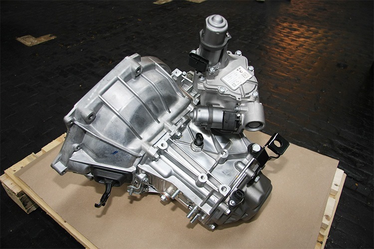
The Lada Priora checkpoint is not the best, but at the same time it has a simple device and can be repaired in a garage with your own hands if you have certain knowledge and skills of such work. For convenience, it is better to dismantle with an assistant. The checkpoint is a heavy knot, and when removed without insurance, you can easily drop it on yourself, getting injured.
Problems with the 2nd gear were initially, from the moment of purchasing this fret priors. Well, how can I say the problem, at first it did not turn on at all, then it began to turn on with a crunch (we are talking about a quick start and switching from 1st to 2nd at 6000-6500 rpm, there were no problems with normal driving).
On the recommendation of his father, he signed up for a service, where he repairs his car. (by the way, the service turned out to be very good, now only there :), located opposite the traffic police)
Since the box had to undergo an autopsy, I ran through the thought to put the 18th row and a pair of 3.9.
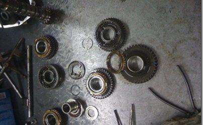
When they disassembled the box, they were not surprised at all
As a result, they were bought and exchanged
I also bought a Kalinovsky cardan along with an anther (you can pull the Priorovsky horseradish :)) and a short-stroke stage.
Symptoms: gears are shifted with complications, gears do not switch / do not turn on / do not turn off, rattling when changing gears, gears "knocks out", gears are turned off spontaneously.
Possible reason: the gearbox parts are out of order.
Tools: flat screwdriver, a set of heads, a set of wrenches, an assembly blade, a hammer, a technological plug in the gearbox hole for wheel drive.
2. Remove the oil level gauge from the gearbox.
3. Place the gearbox vertically on the clutch housing.
4. Unscrew and take out the fastening bolt (1) using a “10” spanner and remove its washer installed under the head. Unscrew the two retaining nuts (3) of the clutch cable bracket and remove the spring washers installed under them. Remove the clutch cable bracket (2) from the gearbox.
5. Unscrew the remaining four rear cover retaining nuts using a 10-inch wrench.
6. Using a screwdriver, pry the boss on the cover, then remove it.
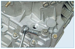
7. Unscrew and remove the fifth gear yoke mounting bolt using a 10-inch spanner. Remove the washer under the bolt head.
8. Prevent the gearbox shafts from turning as follows:
- turn on the fifth gear by shifting down the synchronizer clutch with the fork so that the clutch splines mesh with the gear;
- turn on the third or fourth gear by moving the gear selection rod to the desired position.
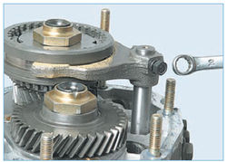
9. Unlock and then loosen the input shaft retaining nut using a 32-bit socket.
10. Using the same tool, unscrew the securing nut of the output shaft, having previously unlocked it.
Note. The fixing nuts of the input and output shafts are tightened with a high torque, and therefore, when unscrewing them, a lot of effort must be applied.
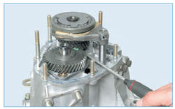
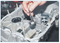
11. Dismantle the driven gear of the fifth gear together with the synchronizer and the output shaft yoke by lifting them with two screwdrivers.
Note. Prevent the synchroniser clutch from sliding off the hub. This is necessary because the synchroniser locking balls may fall apart.
12. Remove the thrust plate from the synchronizer, then remove the fork from the synchronizer sleeve.
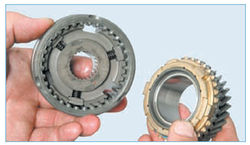
13. Dismantle the fifth gear with the blocking ring from the synchronizer. Mark the relative position of the locking ring (1) and the sleeve (2), and then remove it. This is necessary because during operation the teeth of the ring are worn in to the teeth of the coupling, therefore the correct installation of the ring is very important.
14. Remove the output shaft sleeve.
15. Disconnect the drive gear of the transfer from the input shaft (pay attention to the position of its installation).
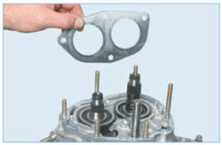
16. Remove the four bearing plate retaining screws using an impact screwdriver. Dismantle the plate (1) and remove the thrust washer (2) from the output shaft.
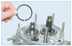
17. Remove the bearing circlips from both shafts by lifting the shafts by hand.
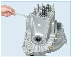
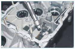
18. Unscrew the three plugs of the fixing elements using a 13-inch spanner. Carefully remove the retainer balls together with the springs.
19. Remove the sealing ring and take out the spring of the fixing element, having previously unscrewed the stopper plug.
20. Remove the retainer ball by tilting the gearbox.
21. Unscrew and remove twelve nuts and remove the securing bolt of the gearbox housings. Pay attention to which nuts the holder (1) and transport eyelet (2) are installed under. Remove the plug (3) inserted in place of one of the drives.
22. Disconnect the gearbox housing and the clutch housing by alternately inserting a screwdriver into the slots along the perimeter of the crankcases.
23. Raising the gearbox housing, turn it counterclockwise so that the crankcase lug (1) comes out from under the gear, then remove the gearbox housing from the clutch housing.
24. Unscrew and remove the fastening bolts of the forks of the first and second, third and fourth gears using a “10” wrench.
25. Remove the shift rod of the first and second gears from the support (3), slightly lifting it.Disengage the stem head (1) from the locking bracket (2) by turning the stem counterclockwise. Remove the rod yoke (4) from the synchronizer coupling groove, and then dismantle the yoke.
Note. Do not mix up the forks when assembling.
26. Disengage the head of the third and fourth gear shift rod from the gear selection lever by turning the rod. Remove the rod from the support, slightly lifting it, then remove the rod together with the fork, removing it from the groove of the synchronizer coupling.
27. Disengage the fifth gear engagement rod head from the locking bracket by turning it. Bring it out of the support and remove the stem.
28. Remove the idler reverse gear axle.
29. Move the reverse idler gear until it stops in the gear selection mechanism, then turn it 30 - 40 degrees. Remove the idler gear by moving it out from under the shaft gears.
30. Simultaneously remove the input and output shafts by slightly shaking them.
31. Remove the differential from the clutch housing.
32. Unscrew and remove the three mounting bolts of the gear selection mechanism using a 10-inch spanner, then remove it.
33. Remove the magnet from the clutch housing.
34. Unscrew the speed sensor fixing nut using a “10” spanner, and then remove the sensor.
35. Replace the speed sensor O-ring if it is damaged or loose.
36. Remove the reversing light switch by unscrewing it from the gearbox housing. There is a metal seal ring underneath.
37. Press out the front bearing of the output shaft using a special puller or screwdriver.
38. Dismantle the oil collector (it is located under the bearing).
39. Press out the input shaft front bearing using a special puller. If you do not have a puller, construct a hook-shaped fixture with stiff wire. Mount the manufactured device into one of the grooves in the crankcase and insert the hook under the bearing. Press the bearing out of the crankcase as follows:
- put a screwdriver in the hook;
- put a block of wood under the screwdriver;
- do not hit with a hammer on the opposite inserted end of the screwdriver;
- alternately rearrange the hook in the grooves.
40. Press the new shaft bearings into the clutch housing up to the stop using a suitable mandrel.
41. Using a screwdriver, pry up the lip of the selector shaft protector, then slide it off the stem support bushing.
42. Unscrew the fastening bolt (3) of the gear selection lever (2). Dismantle the gear selection lever by displacing the rod (1), and then remove the gear selection rod from the clutch housing.
43. If it is necessary to replace the stem joint:
- slide the protection cover off the stem;
- unscrew and remove the hinge fixing bolt.
Note. The bolt is fixed with special TB-1324 glue;
- before screwing in the bolt, clean it from the layer of old glue, and then apply a new one;
- Replace the damaged or lost elasticity / elasticity cover for protecting the stem hinge.
44. If it is necessary to replace the clutch housing:
- remove the bearing from the clutch housing;
- remove the clutch release fork;
- press out the oil seals.
45. Inspect the clutch and gearbox housings, as well as the rear cover. Cracks, chips and other similar damage are not allowed. The seating surfaces should not have nicks, dents, deep marks and similar defects. It is allowed to repair minor damage using abrasive paper. Replace parts if defects are significant.
46. Check the bearing seats in the clutch housing and in the gearbox housing. If damage is found to the seats, the crankcases should be replaced.
47. Check roller bearings.Replace if damaged raceways, cage or rollers. Also, the bearings should be replaced if any play is found.
48. Inspect the gear shift rods for scoring, burrs, worn out holes for fixing elements and other defects. Replace the rods on which they are found.
49. Inspect the axle seals. Tears and traces of warpage are not allowed. Also, the presence of dents, sagging of rubber, deep grooves on their working edge is not allowed. The packing spring must be elastic, not broken or deformed. Defective oil seals must be replaced.
50. Replace damaged and heavily crimped gaskets.
51. Clean the magnet from wear particles of parts. Replace the magnet if cracks appear or the magnetic properties are weakened.
52. Carefully remove the remnants of the old sealing agent from the mating surfaces of the clutch housing and the gearbox housing.
53. Assemble the gearbox in the reverse order of disassembly, taking into account the following points:
- before installing the shafts in the clutch housing, insert the teeth of the shaft gears into engagement;
- liberally lubricate all rubbing parts and assemblies with gear oil;
- place the magnet in its place;
- Apply a sealant around the entire perimeter of the mating surfaces of the clutch housing and rear cover.
54. Install the gearbox.
Qualitative repair of the Priora gearbox carried out by experienced craftsmen. To carry out the work, specialists use only modern equipment and professional tools. Thanks to this approach, masters manage to solve even the most complex problems. The first stage of work is diagnostics. Based on the data obtained, experts determine the most effective method, which should be resorted to in the future.
- for the work of the master, only original spare parts are used (delivery from Togliatti);
In addition to repairs, specialists are ready to modernize the checkpoint. For example, for a reasonable price, you can make a sports gearbox out of a conventional gearbox.
If the driver detects problems with the transmission, highly qualified service specialists can quickly determine the need for repairs. Also, the workshop workers conduct consultations related to the competent maintenance of the vehicle and the features of the new gearbox. The guarantee for the work performed once again confirms the high professionalism of the craftsmen. You can get acquainted with the prices for the services provided in the price list.
Price for the repair of the Priora gearbox : 7000 rubles (price includes: removal, spare parts, repair and installation)
We carry out the disassembly of the gearbox during its repair.
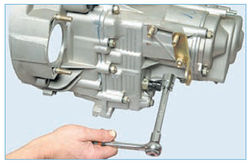
Using the "13" head, unscrew the two nuts securing the bracket for the left support of the power unit and the clutch release cable.
Using the "17" head, unscrew the bracket fastening bolt ...
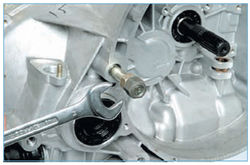
Using the "13" head, unscrew the eye attachment nut ...
… And unscrew the stud from the clutch housing.
Using the "13" head, we unscrew the plug of the retainer of the fork for engaging the reverse gear ...
We take out the retainer spring from the crankcase hole.
Using a magnet, remove the retainer ball.
Using the "13" head, unscrew the four nuts securing the rear crankcase cover.
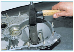
Tapping with a hammer with a plastic head or a conventional hammer through a mandrel made of soft metal on the lid lugs ...
… Remove it from the studs.
Using the spanner wrench "10", unscrew the bolt securing the V gear fork.
We hit the fork through a soft metal drift, including V gear.
With a beard, we straighten the punching points of the collars of the nuts of the primary and secondary shafts.
Head "32" with a powerful knob ...
Prying the driven gear of the V gear with a screwdriver, remove the V gear assembly assembly.
We take out the plug of inclusion of the V gear.
… Remove the V gear with a synchronizer blocking ring.
Remove the synchronizer blocking ring.
We take out the thrust plate of the synchronizer
Use a screwdriver to pry on the sleeve of the driven gear of the V gear ...
... and remove it from the output shaft.
Insert one or two screwdrivers into the gap between the thrust plate and the V-gear drive gear. Prying the gear with a screwdriver (s) ...
… We press it off the input shaft.
Remove the thrust ring from the secondary shaft.
Using an impact screwdriver with a Phillips head PH3, unscrew the four screws securing the bearing thrust plate.
Using the spanner wrench "13", unscrew the three plugs of the clamps of the gear shift forks.
We take out the springs from the nests ...
... and use a magnetic screwdriver to remove the locking balls.
… And remove the ring from the crankcase groove.
Using a 13 spanner spanner, unscrew one bolt and thirteen nuts securing the gearbox housing to the clutch housing.
Having inserted a screwdriver into the groove at the junction of the mating surfaces of the crankcases, carefully raise the gearbox housing ...
We take out the magnet from the recess of the gearbox housing.
Using a 10 spanner spanner, unscrew the bolt securing the I – II gear shift fork to the rod.
Lift the stem up and remove the fork from the groove of the synchronizer sliding sleeve.
Using a 10 spanner spanner, unscrew the bolt securing the 3rd-4th gear shift fork to the rod ...
… And use a screwdriver to remove the stem lever from the gearshift mechanism.
We lift the stem up and remove the fork from the groove of the synchronizer sliding sleeve.
Turning the Vth gear shift fork rod, remove the rod lever from the gear shift mechanism.
We take out the axis of the intermediate gear of the reverse gear.
We take out the intermediate gear of the reverse gear.
Using the "10" head, unscrew the three bolts securing the gearshift mechanism ...
We simultaneously take out the primary and secondary shafts from the roller bearings of the clutch housing.
We take out the differential assembly.
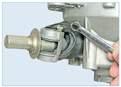
... and use a 10-ring spanner to unscrew the conical screw of the hinge.
Remove the hinge from the rod ...
… With the "10" head, unscrew the tapered screw securing the gear selector.
… Remove the gear selector from the rod.
Using a screwdriver, remove the rollers of the front bearing of the secondary shaft from the separator.
We take out the bearing cage.
Hooking the collar of the outer ring of the bearing with the hook of the impact puller ...
… Press out the outer ring of the bearing.
We remove the oil sump.
We knock out a suitable piece of pipe from the clutch housing ...
We strike through the beard into the end face of the outer ring of the differential bearing ...
Video (click to play).
... and press out the ring.