Details: pzd 14ts 10 DIY repair from a real master for the site my.housecope.com.
Pre-heater diesel 14TS-10. Manual 14TS.451.00.00.00.000-10 RE
This Operation Manual (OM) is intended to study the design, operation and operation rules of the 14TC-10 diesel preheater (hereinafter referred to as the preheater), intended for preheating the diesel engine of trucks of all brands with a liquid cooling system, at an ambient temperature air up to minus 45 ° С.
The complete set of heater properties includes the following functions.
1. Ensuring reliable engine start at low air temperatures.
2. Additional heating of the engine and the passenger compartment with the engine running in severe frost conditions.
3. Heated passenger compartment and windshield (to remove icing) when the engine is not running.
4. Possibility of starting the pre-heater in manual mode for 3 or 8 hours of operation with the simultaneous setting of the "economical" or "normal" operating program. The Manual may not reflect minor design changes made by the manufacturer after this OM was signed for publication.
An example of writing a pre-heater designation when ordering and in documents for other products: "Diesel preheater 14TS-10 TU4591-004-40991176-2003"
2 Main parameters and characteristics
2.1 Heating capacity, kW
2.3 Nominal supply voltage, V 24 V
2.4 Used fuel diesel fuel in accordance with GOST 305 (depending on the ambient temperature)
2.5 Coolant antifreeze, antifreeze
| Video (click to play). |
2.6 Power consumption, W
2.8 Weight of the heater with all accessories, no more than 10 elements, kg
3.1 Installation of the heater and its components must be carried out by specialized organizations.
3.2 The heater may only be used for the purposes specified in these operating instructions.
3.3. It is forbidden to lay the fuel line inside the passenger compartment or cabin of the vehicle.
3.4 A vehicle equipped with a heater must have a fire extinguisher
3.5 The heater must not be used in places where flammable vapors and gases or large amounts of dust can form and accumulate.
3.6 It is prohibited to operate the heater in closed, unventilated rooms.
3.7 When refueling the car with fuel, the heater must be turned off.
3.8 In the event of a malfunction in the heater operation, contact a specialized repair organization authorized by the manufacturer.
3.9 When carrying out electric welding work on the car or repair work on the heater, it is necessary to disconnect it from the battery.
3.10 When installing and dismantling the heater, the safety measures provided for by the rules for working with the electrical network, fuel and fluid systems of the vehicle must be observed.
3.11. It is prohibited to connect the heater to the electric circuit of the vehicle when the engine is running and there is no storage battery.
3.12 Before the first start-up or long break in operation, fill the pre-heater fuel supply system with fuel (vehicle fuel pump).
3.13 It is forbidden to disconnect e-mail. pre-heater supply until the end of the purge cycle.
3.14 The pre-heater is supplied with electricity from the storage battery, regardless of masses car.
3.15 It is prohibited to connect and disconnect the heater connector when the heater power supply is on.
3.16 After the pre-heater is turned off, it should be turned on again no earlier than in 5-10 seconds.
3.17 Failure to comply with the above requirements, the consumer is deprived of the rights to warranty service of the heater.
3.18 For the sake of safe operation of the pre-heater, after three consecutive unsuccessful starts, it is necessary to contact the service department to identify and eliminate the malfunction.
4 Description of the device and operation of the heater
The heater works independently of the vehicle engine.
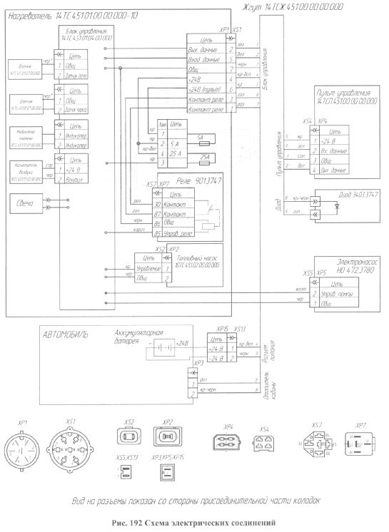
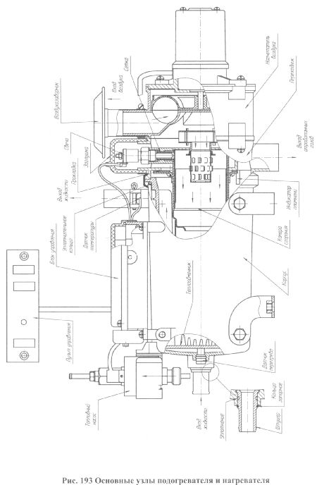
The heater is supplied with fuel and electricity from the vehicle. The heater wiring diagram is shown in Fig. 192.
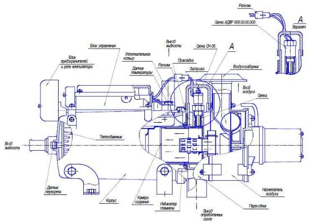
The heater is an autonomous heating device that contains: a heater (the main units of the heater are shown in Fig. 193); a fuel pump for supplying fuel to the combustion chamber;
circulation pump (pump) for forced pumping of the working fluid of the cooling system (antifreeze) through the heat exchange system of the heater;
a control unit that controls the above listed devices according to one of a given program;
a wiring harness for connecting the elements of the heater and the vehicle battery.
The heater can operate in one of two programs: "economic" or "normal". The economical program is distinguished by lower power consumption in the "medium", "small" and "cooling" modes.
The principle of operation of the heater is based on the heating of the liquid of the vehicle engine cooling system, which is forcibly pumped through the heat exchange system of the heater.
The gases from the combustion of the fuel mixture in the combustion chamber are used as a heat source. Through the walls of the heat exchanger, heat is transferred to the coolant of the vehicle's engine cooling system.
When the pre-heater is turned on, testing and monitoring of the performance of the pre-heater elements is carried out: flame indicator, temperature and overheating sensors, pump, air blower motor, spark plug, fuel pump and their electrical circuits. In good condition, the ignition process starts. At the same time, the circulation pump (pump) is turned on.
According to a given program, the combustion chamber is pre-purged and the glow plug is heated to the required temperature. Then, according to the same program, fuel and air are supplied. The combustion process begins in the combustion chamber. After the formation of a stable combustion, the glow plug is switched off. The flame is monitored by a flame indicator. All processes during the operation of the heater are controlled by the control unit.
The control unit monitors the coolant temperature and, depending on the coolant temperature, sets the pre-heater operation modes: "full", "medium" or "low". In the "full" mode, according to the "normal" program, the coolant heats up to 70 ° C, according to the "economical" program up to 55 ° C, and when heated above 70 ° C or 55 ° C, respectively, it switches to the "medium" mode. In the "medium" mode according to the "normal" or "economical" programs, the coolant heats up to a temperature of 75 ° C, and when heated above 75 ° C, the heater switches to the "small" mode. In the "low" mode, the coolant heats up to 80 ° C (for both programs), and when heated above 80 ° C, it switches to the "cooling" mode, while the combustion process stops, the pump continues to work and the car interior is heated. When the liquid is cooled below 55 ° C according to the "normal" program, the heater is automatically switched on again to the "full" mode, and according to the "economical" program to the "medium" mode.
The duration of a full cycle of operation is 3 hours or 8 hours, depending on the position of the switch (see section 6) In addition, it is possible to turn off the heater at any time during the cycle. When a command is given to turn off the pre-heater manually or automatically after the pre-set operating time of the pre-heater has expired, the fuel supply is interrupted and the combustion chamber is purged with air.
Features of automatic control of heater operation in emergency and abnormal situations:
1) if for some reason the pre-heater did not start, the starting process will automatically repeat. After 2 unsuccessful attempts, the pre-heater is turned off;
2) if during the operation of the pre-heater combustion stops, the pre-heater will turn off;
3) when the heater overheats (for example, the circulation of the coolant is disturbed, an air lock, etc.), the heater is automatically turned off;
4) when the voltage drops below 20V or if the voltage rises above 30V, the pre-heater is turned off.
5) in case of emergency shutdown of the heater, the CONTROL LED will start blinking on the control panel. The number of flashes, after a pause, indicates the type of malfunction. For an explanation of the type of malfunction, see section 8 "Operation manual".
Note. Heating the car cab is possible only with the open position of the interior heater tap and a closed ground.
5 Heater control unit (CU)
BU provides control of the heater together with the control panel. BU performs the following functions:
a) initial diagnostics (serviceability check) of the heater units at start-up;
b) diagnostics of the heater units during the entire operation;
c) start-up and automatic operation according to the "normal" or "economical" programs (transition to different modes depending on the temperature of the engine coolant);
d) turning off the heater:
at the end of a given cycle (cycle 3 hours or 8 hours);
in case of loss of performance of one of the monitored nodes;
when the parameters go beyond the permissible limits (temperature, voltage and flame failure in the combustion chamber).
6 Control panel with thermostat
The control panel (hereinafter referred to as the panel) is intended for use as part of the 14TC-10 heater as a device providing manual control of the heater. The remote control is intended for:
starting and stopping the heater in manual mode;
installation of work programs: normal or economical;
setting the duration of the heater operation (3 hours or 8 hours);
cab heater fan control;
showing the state of the pre-heater (works, does not work or does not work due to a malfunction).
6.1 The device of the control panel and work with it.
On the front panel of the control panel there are three key switches (pos. 1, 2 and 3), a LED (pos. 4) and a thermostat knob (pos. 5), see Fig. 194.
Rice. 194 Front panel of the control panel
6.1.1 Switches are designed to execute the following commands:
switch pos. 1 (backlit) is used to start (position "|") and turn off the heater (position "O");
switch pos. 2 is used to set the program of work:
a) normal (lower position of the switch);
b) economical (upper position of the switch);
switch position 3 is used to set the operating time of the heater for 3 hours (on the front surface of the control panel it is marked with a sign 3) or 8 hours (on the front surface of the control panel it is marked with a sign 8).
The position of the switches pos. 2 and 3 can be any; they can be switched during the operation of the heater, i.e. you can change the program of work and the duration of the work. The duration of work after switching will be equal to the time, taking into account the worked.
For example, if you switch from the set time of 8 hours to a duration of 3 hours, and the pre-heater has been operating for 4 hours before switching, the pre-heater will turn off;
thermostat knob pos. 5 serves to control the cab heater fan (provided that the coolant temperature is more than 55 ° С, and the interior heater switch on the panel in the cab is in the "OFF" position and the vehicle weight is on) as follows:
1) when the thermostat knob is set to the extreme left position, the cab heater fan will be turned off;
2) when the thermostat knob is set to the extreme right position, the cab heater fan will operate continuously;
3) when the thermostat knob is installed between the extreme positions, the fan will turn on cyclically. Cycle duration is 10 minutes.
For example, if the knob is set in such a position that the heater fan will work for 4 minutes, then only after 6 minutes it will turn on again for 4 minutes, etc. Thus, it will work until the position of the thermostat knob is changed or until the heater is turned off. After each change in the position of the thermostat knob (between the extreme positions), the next activation of the cab heater fan will occur in the interval from 2 to 8 minutes.
6.1.2 LED pos. 4 indicates the heater status:
-lit - when the heater is in operation;
- blinking - in case of malfunction (emergency). The number of flashes after the pause corresponds to the fault code (see Table 26).
- does not light up - when the heater is not working.
Attention. To re-enable the heater after its automatic shutdown, the switch pos. 1 must be moved to position "O" and not earlier than 2 seconds later to position "I".
7.1 Malfunctions that can be rectified on our own. The heater does not start after switching on, while it is necessary:
Check the presence of fuel in the tank. Check fuses:
o the "ON / OFF" button when turned on on the remote control does not light up - 5 A;
the heater does not start - 25 A;
o the cab heater fan does not work - 8 A.
7.2 All other malfunctions of the pre-heater are automatically indicated by the flashing of the LED on the control panel.
7.3 Typical heater malfunctions and the procedure for their elimination see section 8.
7.4 In case of all malfunctions arising during operation, except for those specified in clause 7.1, it is necessary to contact the repair shop.
8 Malfunctions of elements of the heater control system
8.1 Troubleshooting should be started with checking the contacts of the connectors of the tested circuits, see Table 25, according to the wiring diagram in Fig. 192.
The output signal and voltage are linear with temperature (0 ° C corresponds to 2.73 V and with a 1 ° C increase in temperature, the output signal increases by 10 mV). Check sensor and replace if necessary.
By simple on the block of the temperature sensor, we measure the voltage:
0 = 2,73
+20 = 2.93 volts
+40 = 3,13
... field-effect transistors. in key mode. it is necessary that the appropriate voltage be applied to the gate, and when the onboard voltage drops to 18 and sometimes to 16! volts, then this is catastrophically small, the key goes into linear mode.
... and in the supercharger circuitry, additional circuits
Those buying a supercharger now will have built-in protection against this, but the control unit will be with the old software.
There are 4 screws, you do not need to remove 2 min max and dismantle anything.
And if someone is dissatisfied with the criticism, then I previously noted this company as successful, which managed to create its own product and squeeze foreign competitors, but in this case they have a real jamb and mistakes need to be recognized and corrected, and not thrown customers, it ends badly for the company ...
Removal from machine to machine is not covered by the warranty.
repair can be, but it must be guaranteed in this case and the costs of replacing parts recognized as defective in this case, the manufacturer will have to pay to dealers as far as I understand. but then there should be a massive review for the given details.
and it is necessary to solve this issue not somewhere in the wilds of the droma forum in a private way, but at least by writing a letter to technical support to the official contacts of the manufacturer.
Those. Can't re-solder without complete disassembly?
Definitely a jamb of the structure, voltage drops in the machine are inevitable. And not just a jamb of a design, but a choice of strategy: the production of these engines has been built. Then write in the instructions: before turning on the starter, the pzh must be turned off. Although it burned out just when the pzd itself was turned off, it seems to me that the refusal was provoked by the control unit itself in the purge phase. Then the next time I just didn’t turn on.
By the way, about balancing, no balancing is felt, the vibration is decent.
The 14TC-10 liquid pre-starting diesel heater is designed to warm up an engine with an antifreeze cooling system prior to its direct start at an air temperature of 0 ° to -45 ° C. Works autonomously, powered by electricity from the car itself. It can also operate on diesel fuel, taking it from the tank or from an additional tank, which is included in the PR kit.
Since modification 14 TC 10 has practically no structural differences from other prestarting heaters, its technological characteristics also have static indicators. Thermal conductivity is equal to the following parameters:
- maximum mode - 15.5 kW;
- average - 9 kW;
- minimum - 4 kW.
These indicators are achieved with a fuel consumption of 0.5 to 2 liters. The device PZhD 14TS 10 from 24V operates on diesel fuel in accordance with GOST 305. Antifreeze or antifreeze can be used as a coolant, which is used in the cooling system. As for the power consumption, the following indicators should not be exceeded:
- full mode - 132 W;
- average - 101 W;
- minimum - 77 W;
- during cooling - 47 W.
One working cycle lasts 3-8 hours with manual start mode.
The diesel pre-heater 14TC 10 is an autonomous equipment, therefore it functions independently of the main motor of the car. Power is supplied directly from the vehicle.
Heater circuit Teplostar 14TS-10
The package includes the following items:
- PZhD engine;
- fuel pop for pumping the fuel mixture into the combustion chamber;
- circulation pump, which forcibly pumps antifreeze or antifreeze through the cooling system and heat exchanger;
- control board for adjusting the functioning of all of the above details;
- Remote Control;
- clamps and harnesses.
The principle of operation is to heat the tholos, which, under the influence of the pump, circulates through the heat exchange part of the heater. To heat the liquid in the device, gases from the combustion of fuel in a thermal chamber are used. Thermal energy through the walls of the heat exchanger enters the coolant passing through the cooling system of the PZhD 14.
Wiring diagram
At the time of starting the engine preheater, testing and control of all processes of functioning of the constituent elements is carried out:
- fire indicator;
- temperature controller;
- water pump;
- electronic motor for air heater;
- fuel pump;
- candles and wiring.
If connected correctly, during start-up, ignition occurs, at the same time the circulation pump is activated. The electrical circuit provides 2 main modes of operation:
According to the selected program, a certain amount of fuel is taken from the tank, then the combustion chambers are blown and heated to a predetermined value. The duration of the full cycle of operation in the economy mode is 8 hours, according to the pre-start program - 3 hours. The owner has the ability to stop the operation of the device at any convenient moment.If you turn off the device yourself or after a specified period of time, the fuel supply valve closes and the combustion chamber is blown with clean air.
Working units of the liquid preheater of the engine
In the event of a malfunction of the preheater or an error is detected, the device automatically turns off. For example, a work stoppage may occur under the following circumstances:
- the engine does not start - the starting process is repeated, after two attempts the pre-heater stops functioning completely;
- the flame is extinguished - instantaneous shutdown of the device;
- overheating due to an air lock or a malfunction of the coolant;
- the voltage level has dropped below 20 V or has risen to 30 V.
Regardless of the reason, in case of an unexpected emergency shutdown of the device, the indicator on the control panel will light up. The frequency of the signal is fully consistent with the type of breakdown. You can decipher the trouble codes using the operating instructions.
VIDEO: How the prestarting liquid engine heater works
If the device does not start or any spare part does not work, first of all, you need to pay attention to the contacts and connectors of the electrical circuits.
Electrical circuit
A heating element
Remote Control
It should be noted that most of the faults that require repair are displayed as error codes. Each code has an individual decoding, which is indicated in the instruction manual. Also, using these signals, you can try to fix the problem yourself using the recommendations of specialists.
- The pre-heater does not turn on - the LED indicator is not illuminated
Probably, the pre-heater has problems with the operation of the 25A fuse. Also, the cause of malfunctions can be a breakdown of the control panel, a disruption in the electrical circuit, damage to connectors or oxidation of contacts.
- The system overheats - the indicator blinks 1 time
The device has detected a large difference between the overheating controllers and the temperature sensors. Also, the device that sits out the temperature can give an indicator exceeding 102 ° C. In this case, it is required to check the integrity of the liquid loop and the functioning of the circulation pump.
There is not a small probability of failure of control devices.
- Number of start attempts exceeded - 2 indicator beeps
If the starts were carried out based on the instructions in the operating instructions, it is required to check the presence of a fuel mixture in the tank and the supply system. Such malfunctions may be the result of a breakdown of the air supply device, the gas outlet pipe.
- Open fire - 3 flashes of the diode
Regardless of the modification, whether it is a Binar 12 V GP from the manufacturer Teplostar, you will need to check the volume of fuel or replace it if a low-quality product was used. The fire indicator may also be broken and the fuel filter clogged.
- Engine malfunctions or glow plugs - LED turns on 4 times
It is necessary to inspect the glow plug for serviceability, if necessary, install a new one. A check of the electrical wiring of the air heater motor is also required.
- Broken fire indicator - 5 light turns on
It is necessary to inspect the electrical wires for integrity. It will also not be superfluous to check the ohmic resistance between the indicator connectors. If the break is more than 90 ohms, the fire controller will need to be replaced. The same actions are carried out when an ohmic short-circuit resistance of less than 10 ohms is detected.
- A device that monitors the overheating level or a temperature sensor is broken - 6 consecutive diodes lights up
The output signal flow of electrical voltage settles in a linear relationship.In the starting heater, it is necessary to check the sensor for operability and, if a malfunction is detected, replace it.
- The liquid or fuel pump is out of order - 7 lightings of a light bulb
It is necessary to inspect the electronic wires of the fuel and liquid pump, possibly a short circuit.
- There is no connection between the remote control and the control unit - 8 signals
Check (ring with an indicator screwdriver) the connecting wires and all connectors.
- The device was urgently turned off due to high or low electrical voltage - 9 signals
In this case, it is required to check the battery, thermostat, electrical circuit for functioning. Under normal condition and correct installation in a KAMAZ or a car bus, between contacts XS1 4 and 7 there should be an indicator of no more than 30 V and no less than 20 V.
- Ventilation time interval exceeded - 10 diode flashes
The pre-heater did not have time to completely cool down within the set blowing time. Inspect fire controller, oxygen supply for gas evacuation and combustion.
On average, the price of the device is 26,000 - 28,000 rubles, the cost of installation depends on the individual conditions of the service center, but often does not exceed 13,000 rubles.
The operational period is valid for 18 months from the date of purchase. Also, this parameter can be measured by the mileage - 45,000 km.
- The installation of a liquid diesel engine heater is carried out by a specialized organization that issues a connection guarantee.
- The main purpose of the equipment is to preheat the engine before starting it directly.
- It is strictly forbidden to place the fuel line inside the passenger compartment or driver's cabin.
- The car must have a properly filled fire extinguisher and a first aid kit.
- Turn on equipment in an open area or in a well-ventilated area. Do not use in dusty or dusty areas / warehouses.
- It is forbidden to turn on and use the device while refueling.
- Equipment repair is carried out by a specialized organization.
- Operation in the absence of coolant in the system and fuel in the tank is excluded.
- In the absence of a battery, the heater must not be connected.
- It is forbidden to turn off the device until the motor and fan have come to a complete stop.
- Power supply of the PZhD is carried out from the battery, regardless of the model and carrying capacity of the car.
- After shutdown (emergency or scheduled), they turn on again no earlier than 10 seconds later.
- Ignoring the safety and operating rules of PZhD, the manufacturer and installer have the right to refuse warranty repairs.
- If the equipment does not start three times in a row, it is recommended that you contact the repair service for a functional check.
Features of managing the operation of the PR in an emergency
- if the heater does not start immediately, the starting process will automatically repeat. After two unsuccessful starts in a row, shutdown occurs. After three, you need to contact the repair;
- if the burner turns off during operation of the pre-heater, the process also stops;
- when the heater overheats (violation of the circulation of the coolant, the formation of an air lock in the air duct or fuel line, etc.), the PZhD is automatically turned off;
- when the voltage drops below 20 V or if it rises above 30 V, the heater also automatically turns off - the protection relay is activated.
- in case of emergency shutdown, the CONTROL LED will start blinking on the control panel. The number of flashes, after a pause, shows the type of malfunction (see above in the section Common breakdowns and methods of elimination).
Like any other equipment, PZD requires regular maintenance, which is as follows:
- daily inspection, checking of wires, connectors and contacts, purging air ducts;
- seasonal - when switching to winter operation, when the heater is required to operate;
- annual inspection for potential faults, breaks, burnt circuits, etc.
VIDEO: How to dismantle the PZD

