In detail: radio tape melody zil 1959 DIY repair from a real master for the site my.housecope.com.
Nefanat

Nefanat


Nefanat


vlad
-
Radiola Melody, sold or what?
Nefanat


Nefanat
-
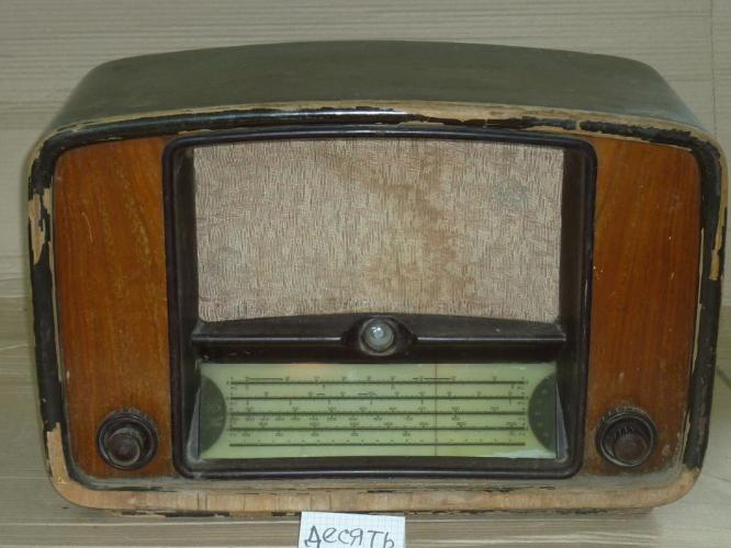
The radiola is disassembled. Available EPU without tonearm, scale, tuning knob, one large and two small, two speakers 2gd-3, chassis with all the necessary lamps. A rag, quite decent. Later I will take a photo, but something is visible in the first message.
The topic can be transferred to the sales of accessories.
| Video (click to play). |
Nefanat
-
In stock remained: a scale, a tuning knob, one large and two small, a chassis with all the necessary lamps, but without a transformer. A rag, quite decent. Later I will take a photo, but something is visible in the first message.
The topic can be transferred to the sales of accessories.
The first thing on my list will be a rather ordinary thing - a tube radio "Latvia". But it is dear to me because it was from her that my fascination with retro equipment began 15 years ago, and it was she who became for me a "learning desk" in terms of repairing equipment.
I got it on the occasion - when my parents bought a summer cottage with a house, the previous owner for some reason did not take it, although before that he tore off and took with him even a leaky carpet from the hallway. At that time, the radio, covered with dust and kitchen grease, was catching the Mayak radio with its last strength. The turntable did not work, the VHF tuning cable was cut off, the "green eye" sat down, and the backlight bulbs had burned out long ago. In fact, it was already more of a piece of furniture than a technical device.
Later I found out that I got the oldest version of the radio, released before simplifying the design and "fighting excesses". In the early 60s, the large "green eye" 6E5C was replaced with a simpler 6E1P and transferred to the scale, and instead of gold paint, they began to use grayish-yellow. And then they released a version of "Latvia-M" with the same filling, but much more boring angular design.
Curiously, in my copy you can still see the names "Stalino" and "Stalingrad" on the scale. In 1961, the name of the leader disappeared from geographical maps and from the scales of radio receivers.
Gradually studying the device of the radio, I repaired something in it every year. First of all, of course, the faulty lamps were replaced. “Latvia” began to play loudly and beautifully, and the reception on all waves improved so much that on a clear evening I caught more than a hundred radio stations from all over the world with a piece of wire.
Next, I restored the VHF cable and replaced the cover stopper, which is not present in the photo above. I didn't even have to look for a donor - it turned out that he just fell inside. It's good that nothing closed.
Most of all I had to tinker with the electric motor of the turntable. It did not burn out, as I thought at first, but simply soured from standing for a long time. I had to disassemble it, grind some details a little and lubricate everything properly.
A couple of years later, it was necessary to replace the block for the power cord, but in general we can say that 99% of the radio is equipped with original parts, including even the native ABC selenium rectifier.
Unlike the Mir radio, to which I have devoted a large cycle of posts, Latvia has not undergone a complete restoration of its appearance. She looks her age and ages naturally.
Sometimes I invite friends over and play them records of the 40s - 50s. This helps keep the turntable mechanism in good working order - it is important that parts do not get stuck. And for the winter I put the rubber roller, which transfers rotation from the motor to the "pancake", in a neutral position so that it does not deform.
And finally - technical characteristics for those interested.
Radiola of the 1st class "Latvia" (RN-59) from 1959 to 1964 was produced at the State Electrotechnical Plant "VEF". The radio receiving path has the ranges DV, SV, two sub-bands HF and VHF. Sensitivity in the ranges DV, SV and KV - 50.100 µV, VHF - 20 µV. Adjacent channel selectivity - 40 dB. IF - 465 KHz and 8.4 MHz. Loudspeakers - two 1GD-1 and two 2GD-8. The rated output power is 1.5 W. The range of reproducible frequencies in terms of sound pressure when receiving in AM is 80.4000 Hz, in FM and during operation of the EPU - 80.10000 Hz. EPU with semi-automatic switching on and automatic switching off has speeds of 33, 45 and 78 rpm. Power consumption during reception - 60 W, during operation of the EPU - 75 W. Dimensions - 530 × 420 × 360 mm, weight - 25 kg.
Is your TV, radio, mobile phone or kettle broken? And you want to create a new topic about this in this forum?
First of all, think about this: imagine that your father / son / brother has an appendicitis pain and you know from the symptoms that it is just appendicitis, but there is no experience of cutting it out, as well as the tool. And you turn on your computer, access the Internet on a medical site with the question: "Help to cut out appendicitis." Do you understand the absurdity of the whole situation? Even if they answer you, it is worth considering factors such as the patient's diabetes, allergies to anesthesia and other medical nuances. I think no one does this in real life and will risk trusting the life of their loved ones with advice from the Internet.
The same is in the repair of radio equipment, although of course these are all the material benefits of modern civilization and in case of unsuccessful repairs, you can always buy a new LCD TV, cell phone, iPAD or computer. And for the repair of such equipment, at least it is necessary to have the appropriate measuring (oscilloscope, multimeter, generator, etc.) and soldering equipment (hairdryer, SMD-hot tweezers, etc.), a schematic diagram, not to mention the necessary knowledge and repair experience.
Let's consider the situation if you are a beginner / advanced radio amateur who solders all sorts of electronic gizmos and has some of the necessary tools. You create an appropriate thread on the repair forum with a short description of “patient symptoms”, ie. for example “Samsung LE40R81B TV does not turn on”. So what? Yes, there can be a lot of reasons for not switching on - from malfunctions in the power system, problems with the processor or flashing firmware in the EEPROM memory.
More advanced users can find the blackened element on the board and attach a photo to the post. However, keep in mind that you replace this radio element with the same one - it is not a fact that your equipment will work. As a rule, something caused the combustion of this element and it could “pull” a couple of other elements along with it, not to mention the fact that it is quite difficult for a non-professional to find a burned-out m / s. Plus, in modern equipment, SMD radio elements are almost universally used, soldering which with an ESPN-40 soldering iron or a Chinese 60-Watt soldering iron you risk overheating the board, peeling tracks, etc. The subsequent restoration of which will be very, very problematic.
The purpose of this post is not any PR of repair shops, but I want to convey to you that sometimes self-repair can be more expensive than taking it to a professional workshop. Although, of course, this is your money and what is better or more risky is up to you.
If you nevertheless decide that you are able to independently repair the radio equipment, then when creating a post, be sure to indicate the full name of the device, modification, year of manufacture, country of origin and other detailed information. If there is a diagram, then attach it to the post or give a link to the source. Write down how long the symptoms have been manifesting, whether there were surges in the supply voltage network, whether there was a repair before that, what was done, what was checked, voltage measurements, oscillograms, etc. From a photo of a motherboard, as a rule, there is little sense, from a photo of a motherboard taken on a mobile phone there is no sense at all. Telepaths live in other forums.
Before creating a post, be sure to use the search on the forum and on the Internet. Read the relevant topics in the subsections, perhaps your problem is typical and has already been discussed. Be sure to read the article Repair strategy
The format of your post should be as follows:
Topics with the title “Help fix the Sony TV” with the content “broken” and a couple of blurred photos of the unscrewed back cover, taken with the 7th iPhone, at night, with a resolution of 8000x6000 pixels are immediately deleted. The more information about the breakdown you put in a post, the more chances you will get a competent answer. Understand that the forum is a system of gratuitous mutual assistance in solving problems and if you are dismissive of writing your post and do not follow the above tips, then the answers to it will be appropriate, if anyone wants to answer at all. Also note that no one should answer instantly or within a day, say, no need to write after 2 hours “That no one can help”, etc. In this case, the topic will be deleted immediately.
You should make every effort to find a breakdown on your own before you get stuck and decide to go to the forum. If you outline the whole process of finding a breakdown in your topic, then the chance of getting help from a highly qualified specialist will be very great.
If you decide to take your broken equipment to the nearest workshop, but do not know where, then perhaps our online cartographic service will help you: workshops on the map (on the left, press all buttons except “Workshops”). You can leave and view user reviews for workshops.
For repairmen and workshops: you can add your services to the map. Find your object on the map from the satellite and click on it with the left mouse button. In the field “Object type:” do not forget to change to “Equipment repair”. Adding is absolutely free! All objects are checked and moderated. A discussion of the service is here.
Today I want to change the subject a little and talk about my other hobby. A couple of years ago, leaving the country house, I noticed something large and beautiful near the dumpster. Turning over the wooden case, I read the word "Peace" on a tarnished metal plate. At that time, I still did not know what kind of thing I got into my hands, but I immediately realized that it was impossible to leave it there. Already at home, having entered the Internet, I found out that I had got the Soviet radio "Mir" M-154R, released in 1956.
It turned out that such a "World" is a welcome exhibit in any collection of an old radio. Alas, the previous owners did not know this. They broke off the top cover of the "Mir", tore out the turntable by the roots, removed almost all the lamps and the back wall somewhere, smashed one of the scales and the tuning indicator, and got dirty and scratched the body.
But I did not despair and decided at all costs to restore the radio. At that time, I had almost no relevant experience, so I had to study collectors' forums for many hours, ask questions to the luminaries there, and sometimes act by trial and error.
I started by cleaning the decorative strip. It turned out that its golden color is not a special coating, but a perennial layer of grease and dirt.
After an hour of washing in a solution of acetic acid, I was able to restore the patch to its original silvery color. I polished the brass base with GOI paste.
The rest of the brass elements were processed in the same way:
On the left, the surface is in its original state, on the right - polished.
Then, with the help of the same acetic acid, I brought the pen to the proper form. They are made from carbolite (the old analogue of plastic), and they can only be washed in an acidic solution, but not in an alkaline one, otherwise they will tarnish. You cannot use regular soap.
After removing the handles (not without the WD-40), I was able to completely disassemble the radio and pull the chassis out of the case.
We had to tinker with the wooden "box": somewhere it cracked, somewhere it was stained with paint, somewhere it lost its veneer.
I glued the waste parts by pressing them with clamps or a load.
While the glue was drying, I was filling the radio.I was lucky with it - it was preserved very well, and after I got hold of all the necessary lamps, the radio began to play with a pleasant, clear sound. I didn't even have to change the electrolytic capacitors - having soldered off one of them, I found out that it had lost no more than 10% of the rated capacity.
The chassis is a little rusty under layers of dirt and dust, but I was able to return it to its presentation with the help of oxalic acid (sold as part of detergents), and in some places I re-painted it with "silver".
Having finished with the chassis, I proceeded to the longest and most difficult part of the restoration - the restoration of the paintwork. I repeat that I have not done anything like this before. In the process of studying the topic, it turned out that the Mir radios were among the last to be covered with shellac, a natural material produced by insects living in tropical countries. Shellac is a substance with a much wider range of applications than the glamorous girls who cover their nails with it might think. The windings of transformers are impregnated with its alcohol solutions, in pyrotechnics it is used as a fuel, before the invention of vinyl, gramophone records were made from it, and it is also edible and even has its own food code - E-904.
But, naturally, I was interested in him not from a gastronomic point of view, but as an unusually beautiful varnish for wood, giving it a special shine and a light golden hue. Before proceeding with the application of varnish, it was necessary to wash off the half-century layers of dirt and repair the defects.
The edges of the case were outlined with black stripes - in order to draw them evenly, I came up with a mask made of regular tape. He came up for these purposes much better than a special paint shop, under which the paint flowed. I used auto refinish enamel in a bottle with a brush.
There are many technologies for applying shellac. The use of almost dry tampons is considered classic, leaving only a hazy mark behind them. With this method, several hundred layers are required! The eastern version of this technology also involves setting fire to the alcohol contained in the varnish. Some restorers claim that shellac can only be applied as a polish, with a special oil. At the same time, to be honest, I hardly believe that during mass production in the USSR, the receiver bodies were varnished for several weeks in 300-600 layers, especially when you consider how inaccurately black stripes were originally drawn on my body.
I have never been able to figure out what technology was used to varnish the Mir hull 60 years ago, and I did not understand which of the modern restorers is right and who is not. Therefore, I decided to find my own way, which would combine, on the one hand, practicality, and on the other, a decent appearance. And after several experiments, I was convinced that a good result is obtained by applying shellac with a thick synthetic brush in 8-10 layers with intermediate drying and sanding each.
The varnish should be applied in long strokes strictly along the grain, from edge to edge. The brush must be wrung out thoroughly before applying, making sure that the fibers do not fluff. The strips of varnish must be done quickly and with a slight overlap - then each subsequent one, without having time to harden, will mix with the previous one, and as a result, you get a flat surface without steps.
Side elements before and after varnishing:
The chamfer at the bottom of the front panel, as well as the back of the case, I tinted with ink (as it was in the original).
Finally, it's time for the final build. By that time, I had got hold of many of the missing parts:
In general, Mir is not the most repairman-friendly device. It is impossible to get close to many of its nodes without disassembling the structure completely, and some parts, once removed, then it is very difficult to put them back.For example, all the elements shown in the next photo must be combined "by weight" and inserted at the same time, and only then they can be fixed.
I did it only once from the fifth. If after that it turned out that I had confused any scales, I would probably have shot myself.
Then the assembly process went more vigorous, and I even made a gif out of it.
The amplifier was developed at the dawn of semiconductor electronics. This is the standard scheme used in almost all radio systems of that time. The power of such an amplifier largely depends on the supply voltage, the range of which is quite wide. To drive the output stage, germanium transistors are used, which have not been produced for a long time. By the way, all transistors (with the exception of the output stage transistors) are germanium.
Despite its simplicity, the amplifier provides reasonably good sound quality and can be configured for classroom use. The transistors of the output stage are installed on a sufficiently large heat sinks, although overheating was not observed during operation. The power of the amplifier can be increased by using more powerful transistors in the output stage. In this case, the supply voltage must also be increased.
The ULF circuit starts working from 3 Volts. The maximum supply voltage level is no more than 30 Volts. The input capacitor can have literally any capacitance. In my case, I used the first capacitor that came to hand. The capacitor voltage is also unimportant. The whole circuit is mounted on a getinax board (my least favorite material).
You can see the fuse on the power line on the board. The capacitors of the Yerevan plant are immediately striking. Probably, the capacitors have long been out of order, or rather, they have lost most of the initial capacitance.
But I decided not to change anything on the board. Then the power amplifier was turned on. I was amazed - the scheme worked! Despite the significantly low power supply, the amplifier played excellently.
Of course, this ULF cannot be compared to the ultra-linear Linsley-Hood scheme, but it plays well for its age.
Melody-104 stereo is a stereophonic block radio, which includes: a radio receiver for long, medium, short and VHF radio waves; turntable with II EPU-62SP (see the description of the player and this EPU at the link); two acoustic systems 6АС-2 (quite original design, with two speakers - LF 10GD-34 and in front of it HF - 3GD-2). The amplifier is located in the radio receiver unit. Serial production of this radio began in 1978 at the Popov Riga Radio Plant - Radiotehnika RRR.
Outwardly, this radio is very difficult to distinguish from Melody 101-stereo, only with a slightly different design of the player and other EPUs in it. and internally the same, because 104-stereo Melodies is the same 101-stereo Melodies, with minor modifications. The 104-stereo melodies were produced in three types, essentially the same: in two, the difference was in completing the turntable with a corundum or diamond needle, and the third used an EPU with a magnetic pickup head GZM-105 (IIEPU-62SM). The further development of this radio was the emergence of the stereophonic radio Melody-105-stereo, which was an improvement in the device under consideration today, including externally.
There are many descriptions and photographs of this radio on the Internet, so I will not repeat myself and will post only those materials that do not exist, I think they will quite logically complement the available information.
U1 - VHF unit. Stands alone, in its standard performance of those years. aluminum screen case, steel bottom. Under it is a board, marking Cr6.672.111. The board has two transistors GT313A, one GT322A, three diodes (varicaps) KVS111B.
Click on the picture to enlarge!
U2 - block KSDV (AM tract). The board is marked Cr6672045. On the side of the tracks there is only the inscription “KSDV”. There are a lot of KSO-type capacitors on the board.
Click on the picture to enlarge!
Click on the picture to enlarge!
U3 - MA unit (magnetic antenna) - I don’t give a photo, because it’s just a rotary mechanism - a ferrite rod with coiled coils.
U4 - block R (VHF tuner). Includes four push-button switches of the P2K type and three variable resistors of the SP3-26 type, marking - Сг6672043.
Click on the picture to enlarge!
Click on the picture to enlarge!
U5 - IF block (intermediate frequency). It is marked Сг2068054, from the side of the tracks - 104 PCh
Click on the picture to enlarge!
Click on the picture to enlarge!
U6 - CD unit (stereo decoder unit), is designed to process the reception of stereophonic radio programs. In the Melody-101-stereo radio, this unit was purely transistor, in the Melody-104-stereo it was modernized and its basis was the K553UD1A microcircuit. When working with stereo programs, the indicator on the front panel will light up. There are markings on the board: Cr2204009 on the front side and Cr7102264 on the side of the conductors.
Click on the picture to enlarge!
Click on the picture to enlarge!
Click on the picture to enlarge!
U7 - ULF-P unit (pre-amplification unit). It has a marking: Сг2.068.055 and an inscription on the side of the tracks УНЧ-П. On the board there is a pair of MP41 transistors, also rarely found K40P-2a, mica capacitors KSO, MBM, etc.
Click on the picture to enlarge!
Click on the picture to enlarge!
U8 - ULF-T unit (tone control unit). On the side of the tracks, there is one ULF-T marking and illegible stamps (apparently OTK). On the front, the marking is Сг2068056. On this board, four slider variable resistors are soldered: two SP3-23V for 33 kOhm, two SP3-23a4 also for 33 kOhm.
Click on the picture to enlarge!
U9 - ULF-O (block of terminal amplifiers). Marking: Сг6672039. The board consists of two completely identical parts - amplifiers for both channels. Large electrolytic capacitors of the K50-12 series are characteristic, as well as powerful transistors KT805B brought out of the board - 2 pieces, and KT808A - 2 pieces. They are bolted to the aluminum sheet of the rear wall of the radio, which acts as a cooling radiator. In the photo, these conclusions are blue wires. There are also transistors on the board: a pair of GT404Zh, a pair of GT402Zh, a pair of P308 and a pair of MP40A.
Click on the picture to enlarge!
Click on the picture to enlarge!
U10 - Power supply unit. It consists of a transformer with a bundle of capacitors, a diode bridge, a stabilizer, fuses and an on / off button, as well as a separate board, which is marked Сг6872042 and the BP inscription on the side of the tracks.
Click on the picture to enlarge!
Click on the picture to enlarge!
Power Supply - transformer, stabilizers, rectifiers, etc. Capacitors of the MBM, K50-12, K50-3 types, the MPNS-1 network type switch, the PKNCH1-1 type circuit breaker were used. Transformer TSA-70-6, designed to power transistor equipment, was used in a variety of models of radio equipment.
Click on the picture to enlarge!
KPE - variable capacitor (KPE-3 10.430 pF). There are no markings on the device.
This is, in general, all. the presented photographs are reduced and compressed - there are originals and if there is a need for them, I will post them.
Thank you, can you help with the button?
means, what wild people do? wild people whisper her breath when matches and carnations are poured into Dean's speaker connectors instead of standard plugs
from this the weekend KT805 takes off, and often and even rather the "pre-weekend" GT402 / GT404
after that, the fuses on the power amplifier board start to fly out stably
after that, wild people happily puff their favorite carnations instead of these fuses, smoke comes from the power transformer, but this never helps them
and the item falls on the hammer for 100.5 million money with the postscript "I did not check its performance, there is no outlet in the house"
hanging there for seven or ten years
then he gets bored and is carried to the side of the trash heap.
in short, the transistors there, in principle, can really be checked without even desoldering
and instead of a fuse for testing, you can shove one or two consecutive light bulbs from the ZIL-130, they are 24 Volts
You will hardly find GT402 / GT404 easily, but KT814 / 815 will be quite suitable there - especially if you put another “same” one “in the same direction” in series with D3 and D4 and adjust the quiescent current
after reviving the power amplifier, it turns out that there will be no sound in one channel anyway. and in the other as from the back
as a rule, the reason is one (or even five. Or even all) of about a dozen electrolytes on a board with tone controls. It is rather unusual to remove this board, but it is quite humanly possible.
but in general it is like an unch - a terrible glucodromine, even when it was relevant
well and 2epu guard - vinyl killer
in general, what kind of vega-type epu with a Polish panel, a homemade one for it on lm3886 or younger 1875, will be incomparably better
and give the melody to the pioneers.
it is not worth the cost of restoration at all

Radiola "Latvia" 63rd year of release, the insides do not work! I will remodel but what?
ASK FOR IDEAS What to make of it? Write ideas, sketches, diagrams, descriptions, I will consider all the most suitable trouble to embody! I'll post my thoughts later.
LEDs + CD changer + dvd player. Refine, paint. A sub can be built into it and can be used under a TV set as a cinema)
You will definitely not do without LEDs! I guarantee! A CD-changer is not relevant these days! Instead, you can purchase a radio tape recorder with a usb output and connect a removable hard drive with a large volume. Although it has the same functions from the previous comment. Sub made notes! Thanks!
If you do not keep the appearance in the original, then just throw it away. Otherwise, alas, it's just a wooden box that can be adapted for anything ... Drag and drop the computer stuffing into it; glue or pick up a finished aquarium; knead a pillow there, and make a place for a cat or a cat if there is ... There are many options.
If you keep the original look, then in my opinion it can be quite an expensive and troublesome pleasure to redo it.
1. As an option, everything is restored and repaired - but in addition to the skill, original (or their analogs) spare parts are needed here. And as a result, we can get a "music box" with a playback quality of 63 years. And few people have records left, so basically it will be a large and bulky radio.
2. Another option. It is quite an expensive pleasure to change the filling for a new one and adapt it to this case. So you need to insert at least an amplifier there, which costs about 5 thousand (it can be more expensive), while in fact you need to disassemble a new thing - throw out the case, adapt the amplifier control panel for these buttons (this is apparently from the amplifier board to pull the wires to " old "buttons, but they also need to be modernized inside). Then look at what is on the market, something that reads DVD, USB and other storage media (and this is a personal matter and the device can again cost a pretty penny), and place this part where the player was. And so on, that is, a lot of hassle.
3. Take option 2 in the amplifier part and push the computer stuffing into it. With a computer it can turn out to be more interesting, well, firstly, the network interface, secondly, the hard drive, thirdly USB ... But there may be several options again: a) buy a touchscreen monitor and screw it to the cover of the player compartment (an expensive pleasure) and b) insert the motherboard with HDMI output and connect to the TV directly, control using bluetooth keyboard and mouse.
4. Again, we take option 2 and plug in a device like this, for example - it takes up less space than a computer and control from the remote control (but the infrared port for the remote control must be displayed) and we carefully connect everything in one heap ....
Here is such a plan came to mind, though in a "hurry" ...
But. In a hurry - so many options. Immediately visible with the design on you!
1. On the first point: I completely agree!
2. More interesting! If you use automotive technology, as in https://my.housecope.com/wp-content/uploads/ext/1470/blogs/ruller/muzykalnaya-korobka-v-stile-retro, only adapt the buttons and knobs to the original. Or a used one is cheaper to find, because the building doesn’t count, there was a live vnutryanka.
3. Interesting! But many times more expensive than the 2nd point, tk. to have a second computer, even with an amp but weaker than the first, I see no reason.And a powerful computer is now also worth a lot! And I don’t like a computer in some way, it’s easier to paint a system unit under an airbrush.
4. Excellent! I will collect information on this issue! And collect your and certainly your thoughts together!
I'll start with the topic - the second computer. there are metrinks with passive cooling like this
processor - Intel Atom D425 1.8 GHz already installed (processor replacement is not possible)
RAM -SO-DIMM DDR3 800 MHz
The price of the issue is 2.500 scars + you need a power broker, RAM and a hard disk (or install the system on a USB flash drive)
In theory, not so expensive. One thing is bad that there is no HDMI, but it also depends on the TV (monitor).
And now about the auto technique. I have not encountered auto-amplifiers (not such a FAN of car music - it plays a regular one and okay), but what about the radio tape recorders. True, I did not understand, but I will make the following assumption (if something is wrong, sorry)
I think it's easier to stick it in. 1. it is not so difficult to find the radio tape recorder itself, it is probably possible without a panel (the panels are stolen, and then people have an unnecessary radio tape recorder lying around). In the socket, as a rule, only buttons, but sometimes USB and AUX ports. Here I do not know how they are integrated there, but I think the connector is just removed. The only thing we lose is the screen ... Although it’s probably better with the panel - you can simply turn it around as you please.
2. under the socket, as a rule, there are terminals for connecting it to the device ...

I think I can call them, or search the internet for device diagrams. And already from these clamps to throw wires on the native "retro" buttons.
There is one more idea, but again with a computer that you “don’t like”. Wait photoshop and throw it (comment floated above) - watch ^).
I am more and more inclined to auto technology! But there is a problem with the 12V DC power supply. We need a very powerful one so that the whole filling is enough! Is an amplifier needed? I also have enough power of a conventional radio! I rarely add even half the sound, but this device will be used in an apartment with children and neighbors !?
Somehow people from another, one might say, similar site lit up here. Climbing on it, I came across one article related to alterations of the computer's power supply. Looking now to give a link, I found a few more there - here are the links ...
As for the power, the power supplies are also of different capacities ...
There is an amp and speakers near the house itself, which seem to be quite good, but I turned on the full only once or twice, and then just see the opportunity!

I think the idea is clear, we install the netbook, firmly fix it so that when the lid is opened it also opens. The price of netbooks is now about 10 thousand (new). Netbooks have plenty of outputs, stick whatever comes your way. (photoshopped in a hurry - at work - so the quality, just to understand the idea)

I advise you to read this article, it may come in handy.
Very interesting. I'll check it by experience, but for some reason I'm sure that I'll do it (from my own speakers)!
If you are restoring vinyl, you can consider these options.
The easiest way to repair it, because the condition is not bad judging by its appearance. But then friends will envy the work of the receiver on VHF (FM-1) - a very good, clean sound. And twisting the old record is also cool. I have a functioning "Belarus" in 1958, now I am restoring "Rodina" in 1947. Good luck!
The thing is quite antique, interesting, and you need to treat it with respect, without rushing, it has already been mocked over it. Since, I repeat, the thing itself is “in itself”, it is undesirable to add non-typical details (multi-colored LEDs, neon lighting, chrome moldings, etc.), otherwise it will be like a lada a penny in a regional center.
Var. 1: amplifier. To restore the appearance as close as possible to the original, it should still have such graceful legs, if you manage to put it - gorgeous! Throwing out all the insides, leaving only the original panel illumination (an ordinary 15-25 W bulb), mount the amplifier inside, so that it is possible to connect different carriers from behind; by and large, enough wires to connect an mp3 player. The amplifier should be equipped with a remote control, you do not need to change any knobs-mechanisms, everything is from the remote control, the main thing is to ensure normal ventilation.In place of the old speakers, mount modern, human, not necessarily powerful ones, he doesn't stand on the square. For the sake of reliability, it is possible to also spin the vinyl (stick any Chinese engine). As a result, we have a stand-alone vintage amplifier with a modern sound.
Var. 2: music center. Everything is the same, only to embed the player so that there is access to its panel: for example, into the side of the radio. By the way, here you can show off, and put light music in the space under the lid (both real and just all kinds of blinkers, spinning lights, strobe lights, LEDs, etc.) With the lid closed, everything is strict, opened the lid, turned on - and everything blinks on surprise to guests.
Var. 3: refrigerator. We restore the appearance, buy a car refrigerator, put it inside, load beer and water, wait for guests. The advantage of the design is that the refrigerator can be used separately from the radio.
Var. 4: vandal decorative. We restore the appearance, strengthen the fastening of all front parts with glue, etc. With an electric jigsaw, or something else, we cut the body somehow diagonally, without affecting the front and upper parts, we make a mount, we hang it on the wall, as if the radio was stuck at an angle in the wall. You can add some lamps by making ventilation, there will be a sconce. It is possible to embed a mechanism from a Chinese clock in the area of the front columns, and outside the hands, there is already some benefit.
": June 29, 2007, 16:22:31"
I'll try to transfer from>
(Paul.)
Wed Sep 06, 2006 21:19 Post subject: Data bank on scales and not only.
Dear forum users.
After consulting with my comrades, I decided (just kidding). It was decided to create a data bank on scales. I have two receivers, barely alive, ARZ and Riga T-755, the scales are separate. Serey (Technician-San) will bring his own records. This Sunday we will put in order everything that you saw in the “Club” (I am writing in quotes, because I’m not sure if there’s any sense yet), connect the scanner, test it, clean up the back rooms, I have a large collection of pens, I’m like I put it on the forum for identification, so the next step is a databank of pens.
If anyone has anything to say. forward.
Paul.
(Paul.)
Here I will make a list of the scales I have. It will turn out to be a kind of data bank.
Foreign radios and radios.
1. Radio receiver Philips "Achen Super D-57" (Crutch). Size 280x952x3 mm.
2. Radio receiver Philips "Aachen Super D 63 X" ... Dimensions 100x242x2 mm.
3. Radio receiver "Reflex Super" ... Size 270 × 95 mm.
4. Siemens radio receiver "Kammermusik-Schatulle 85W" ... Dimensions 132x262x2.5 mm.
5. Radio receiver "EAK Super 64/50 GWP" ... Dimensions 182x53x2.2 mm.
6. Radio receiver "Telefunken T349WL". ... The size
SAMPLES OF SCANNED SCALES:
No. 10. Radiola "Belarus-57" .
No. 11. Radiola "Belarus-59" .
No. 12. Radiola "Belarus-62" .
No. 13. Radio tape recorder "Vaiva" .
No. 14. Radiola Volga Size 500x105x3 mm.
No. 16. Radio receiver "VEF-Accord" ... Size 530x90x2 mm.
No. 17. Radio receiver "VEFAR MD / 37" ... Size 223x63x2 mm.
The real scale is made on plexiglass, and therefore on many receivers there are holes burned by backlight bulbs.
The first photos with a hole, the red part of the scale is on - the DV range is on; the yellow part of the scale is on - CB band is on, red and yellow are on together - HF band is on.


No. 21. Radio receiver "VEFSUPER M517" : Diameter 166mm, hole 12mm. Protective glass - 166 mm.
No. 27. Radio receiver Iskra-53 :

And this photo was sent t ras, with a postscript:
A scan of the Iskra scale and its reconstruction in full size (130x55 mm.)
The original scale is made on plain paper between two glasses of 1.5 mm.
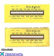

No. 32. Radiola "Cantata-203" (gray-blue scale) Size 450х143х3 mm
No. 34. Radiola "Latvia-M" ... Size 520x120x4 mm.
No. 37. Radio receiver "Latvia M137" ... Size 400x80x5 3 mm.
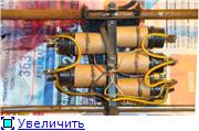
The scale consists of two glasses. On the first glass, 5 mm thick, ranges are applied (gold paint). The second glass is painted with cherry, transparent paint, the ends of the glass are sealed to keep out light. Above the scale, three bulbs shine, which are in the case, and the light enters only the end of the first glass. Behind the scale is a movable carriage (instead of an arrow), on which there are five bulbs, which supply light to the windows.And it turns out that a red dot is on the illuminated scale.


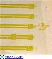

This is the illumination of the scale at the top.


And this is the arrow carriage.


No. 40. Radio receiver "Minsk" (1948, apparatus of A. Revonchenkov):

Back side and general view.

No. 41. Radiola "Minsk-R7" Dimensions 323 x 88 x 4 mm.
No. 42. Radio receiver and radio tape "Minsk-55" .
No. 43. Radio receiver "Minsk-58" .
No. 44. Radiola "Minsk-61" .
No. 47. Radio receiver "Moskvich-V" (Sarapul Radio Plant named after Ordzhonikidze):
No. 50. Radiola "Muromets" ... The size is 460x98x3 mm.
No. 54. Radio receiver "Octave". Size 518 x 100 x 4 mm.
No. 56. Radiola "Dawn" .
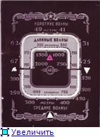
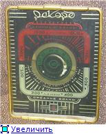

No. 72. Radio receiver "Riga T-689" .
No. 74. Radiola "Rigonda-stereo" .
No. 78. Radio tape recorder "Romance-M" .
No. 82. Radio receiver "Firework" ... Dimensions 238x147x2 mm.
This is the early receiver scale.
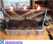

Scale restoration process.
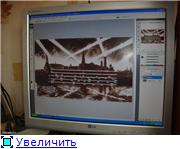

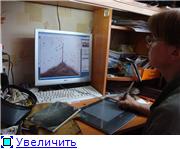

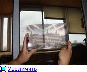

It worked out well.
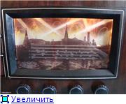

No. 85. Radio receiver "SVD-9" :
Round.
Dimensions: diameter 120 mm, hole 5 mm.
The first photos are what the original looked like.
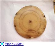
Donor, i.e. used photo for the manufacture of a new Dmitry Guryanov.
In the end, this is what happened.
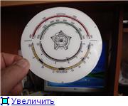

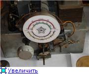

If you delve into history, here is a photo of an American parent, then our subsequent variations. All these photos are borrowed from Dm. Guryanova, for which thanks to him!
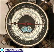

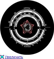

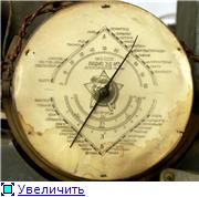

No. 89. Radiola Ural-49 :
No. 92. Radiola Ural-57 :
No. 95. Radio receiver "The festival" Size 540 x 120 x 4 mm.
The scale was produced in two versions.
Option number 1, these are receivers produced before 1959-60. This scale is from a receiver released in October 1959.


This is how it glows.


Option number 2, these are receivers produced after 1960. This scale is from a receiver released in December 1961.


And this is how this one glows.

No. 96. Radio control panel "The festival" :
The first photo is mine, the second from Taras.
No. 97. Radiola "Estonia-2" .
No. 100. Radiola "Estonia-55" .
No. 101. Radio receiver "VV-662 “. Size 310x120x3 mm
No. 102. Radio receiver "6N-1" ... Dimensions 168 × 88 mm.
This is a photo from my receiver (dimensions from it):
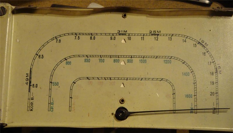
This scan was sent by Nikolay Nikolaevich (tttaras):
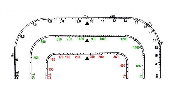
You can download from this topic:
This is a photo of the scale from the Internet:
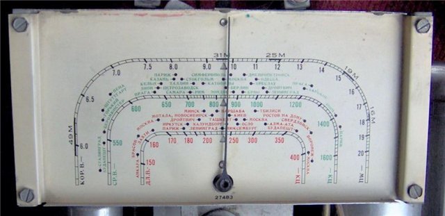
This scan was sent by Nikolay Nikolaevich (tttaras):
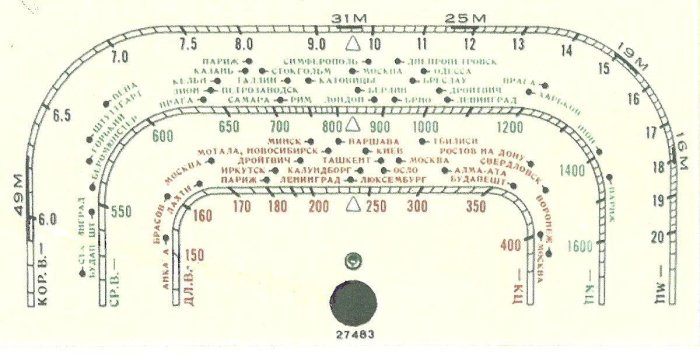
You can download from this topic:
Foreign radios and radios:
1. Radio receiver Philips "Achen Super D 57" (Crutch). Size 280x952x3 mm.

2. Radio receiver Philips “Aachen Super D 63 X”. Dimensions 100x242x2 mm.


3. Radio receiver "Reflex Super" ... Size 270x95x2 mm (material - plastic).


4. Radio receiver Siemens "Kammermusik-Schatulle 85W" ... Dimensions 132x262x2.5 mm.
5. Radio receiver "EAK Super 64/50 GWP" ... Dimensions 182x53x2.2 mm.
Since the scale is transparent, I put a black substrate.


Last edited by OldradioXX (Fri 24 Aug 2018 - 8:16); edited 255 times in total
| Video (click to play). |

