In detail: do-it-yourself adsl modem repair from a real master for the site my.housecope.com.
Something from my own experience. In principle, I have already posted a part on other forums, but I will repeat it with additions here, I hope it will be useful to someone.
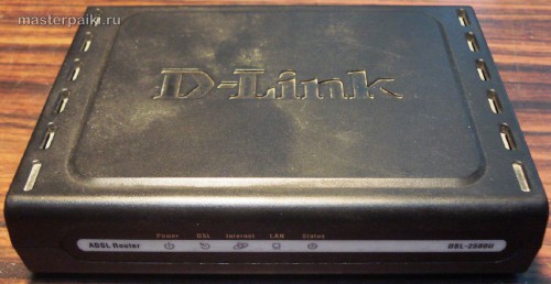
1. A characteristic symptom of one of the most common malfunctions of D-Link DSL-2500U / BRU / C (H / W Ver: C1) and DSL-2520U / BRU / C (H / W Ver: C1) - immediately after switching on, they light up and do not 2 LEDs go out, Power and DSL, the modem does not boot, well, of course, the WEB interface is not available.
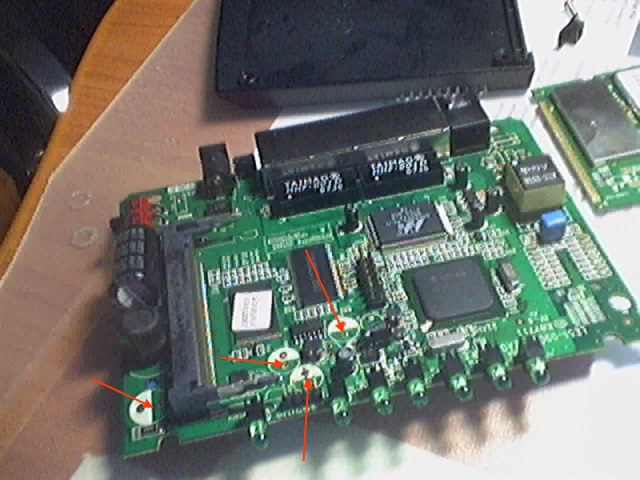
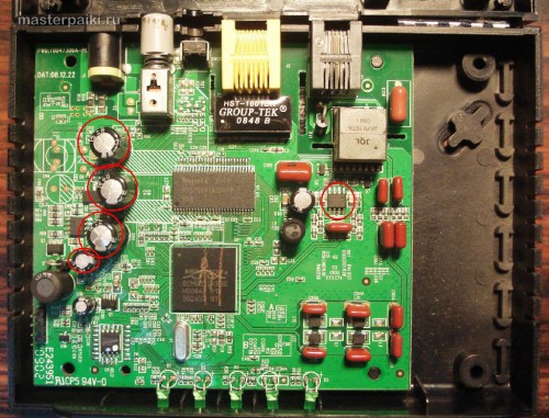
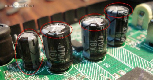
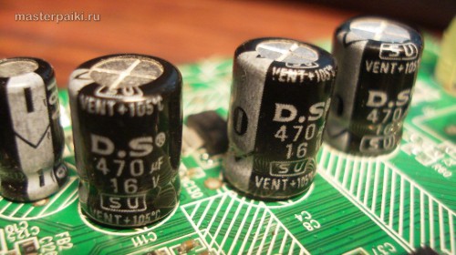
We open the case, carefully examine the electrolytic capacitors C8 (470mF 16v), C14 (100mF 16v, aka C10, depending on which side the marking is read), C32 (470mF 16v), C111 (470mF 16v). They are all next to each other, almost in one line on the board. If they are swollen, we change. Even if they are not swollen, but manufactured by Jakec, we change to capacitors from more decent companies, and preferably with a maximum operating temperature of 105 degrees Celsius, not 85. Yes, C14 does not swell, but we must change it in any case, and put instead it is not 100, but 220 or 330 microfarads. Instead of the rest, which are at 470, you can have similar ones, or you can have a higher capacity, up to 1000 microfarads, if only they fit into the case in height. In terms of voltage, it is possible for 10 volts, and C14 - even for 6.3 volts. If you put polymer capacitors, then C14, in theory, can be 4 volts.
Note 1: If replacing the capacitors did not help, and the modem continues to fail to boot (i.e. after switching on the DSL still does not go out, etc.), then the most likely problem is with the firmware, i.e. with firmware in a flash drive. But here, most likely, you will need an appropriate programmer.
Note 2: If the LAN LED is also on and off immediately, i.e. 3 LEDs are on (the LAN cable is not connected), and replacing the capacitors did not help, then you can still try to replace the 64 MHz quartz.
| Video (click to play). |
The book deals with practical issues related to the repair of personal computers at home or office.
After reading it, you will learn about methods for eliminating common computer malfunctions, learn how to check its performance, identify devices that have failed, and select a suitable replacement for them. The pages of this publication provide recommendations on how to prevent problems and keep your computer running. The material is presented in a simple and intelligible form, so even a novice user will be able to understand it.
The main malfunctions of modems
The modem's input circuits can be damaged by lightning storms if it is connected to a telephone line. Therefore, in a thunderstorm, it is required not only to turn off the PC, but also ALWAYS disconnect the modem from the telephone line.
When starting to repair a modem, first of all, you need to visually inspect it. Malfunctions after a thunderstorm are often immediately visible. Look at the pull-up resistor and ICs. Cracks and chips may be visible on them.
After visual inspection, turn on the power. Check if the LEDs are on. Connect the modem to the telephone line.
Immediately after connecting, the modem should not "occupy" the line. Call your landline phone number, for example, from a mobile phone.
If the line is busy, it means that the modem is "seizing" the line. If there is no “busy” signal, the loop is not closed and is in its original - good condition. If the modem occupies the line, then you should check the key or relay, or protective elements, diode bridge.
Then check if the modem picks up the phone after the command. Try using the Hyper Terminal program (available in Windows) and issue the ATH1 command to pick up the handset. Make sure your modem has completed it.
After the ATH0 command, the modem should hang up.If the modem does not "pick up" the phone, you should check the resistor, relay, diode bridge, protective elements, key transistor, zener diode.
If the AT commands do not work, then the port chip may be replaced.
If the line supports tone dialing, you can issue the ATDTxxxxx command, or ATDPxxxxx for pulse dialing, where xxxxx is the phone number.
If the modem reported - No Dial Tone, check the zener diode, transistors, if everything is checked and correct, then the microcircuit may be out of order.
If the transformer is out of order, the load resistor - low-impedance resistance - 5-20 Ohm could fail along with it. The contacts of the reed relay may also fail, and the optoelectronic relay has an internal field-effect transistor.
In addition, a zener diode may turn out to be faulty, which can be changed to any one with a stabilization voltage of about 9 V.
Under the cover of the router we see an electronic board with swollen condensers... Usually capacitors overheat and lose capacity C8 - 470 μF x 16 V, C14 - 100 μF x 16 V, C32 - 470 μF x 16 V, C111 - 470 μF x 16 V. We change them to capacitors of the same or larger capacity.
Capacitor C14 is better replace with 220 uF.
Also, sometimes the microcircuit fails. U2 Broadcom 6301KSG... I found a solution to this problem here. The source indicates that the microcircuit can be replaced by AD45048.
Which in turn is quite simple replaced by assembly on favorite KT315G and resistors MLT-0.125 430 Ohm. True, due to the spread in the current transfer coefficient, you have to select resistors for a stable Internet speed. Also transistors can replace with C945, and resistors can be selected up to 20 kOhm.
Among other frequent malfunctions of D-link modems, a breakdown of an external power supply is often encountered. In this case, the connection with the network may also be lost and the modem itself may periodically fall off. In this case, the repair will consist in replacing the filtering electrolytic capacitors in the power supply.
This concludes the note about repairing the D-link modem DSL-2500U... Hope your modem will work stably for many years.
Happy renovation to everyone.
The Solder Master is with you.
Yes, they have already begun to sulk again, immediately began to set the power supply with a margin of 35 volts, although the reason is rather in the temperature regime.
bridge diode leakage first cause of swelling
hence the heating of the chips, they apparently don't like the change either))
Valera (ID 176) That's right, but it is excluded primarily by an external stabilized power supply.
The satellites of Glonas also swell litas)))))
Optics will not reach villages and villages soon, so they are in demand even more
Just put in normal low ESR electrolytes and you should be fine. Checked repeatedly.
Conders have been blowing in every second car lately
It's no secret that dial-up modems are a thing of the past, and with them the fancy sounds that this modem made.Therefore, here we will talk about newer ADSL modems, the main malfunction of which mainly manifests itself in the summer period, when the air temperature exceeds all conceivable limits.
Despite the fact that warming up the modem is an average static phenomenon and it is allowed by the manufacturer of the device, you should keep your ears open, or rather the organs of touch. Modem warming up causes unstable internet connection.
Symptoms can be different: resetting the Internet connection (after turning it off and on, there is a connection, after a while the situation repeats itself, and it is necessary to turn it off and on again), the link indicator blinks, but cannot stop (the connection is not established), reset the modem settings, etc. etc.
When the modem is opened, we find swollen, leaking capacitors on the board, usually those that stand do not inspire confidence. They need to be replaced with high-temperature 105 ° C, Jamicon will do. If the situation is force majeure and Internet access is necessary, at first any of the same denomination from your equipment is put. Often, such a repair does not take much time and effort, and even more so money, and the ADSL modem after that works happily ever after :)
The Dlink 2600U modem stopped working after a thunderstorm.
I decided to measure the voltage at the output of the power supply. There is no voltage.
Soaked the seam with solvent to disassemble.
I rang the bell, the limiting resistor was cut off and three diodes on the diode bridge were broken.
Also, the PWM microcircuit was shortened. When I removed the radiator there was soot.
I did not find the microcircuit I had to buy a 12V 1A power supply.
The plug turned out to be different.
After plugging into an outlet, the modem began to respond to the power button.
Checked on the telephone line, everything works.
And what does the modem have to do with the repair of the power supply?
And not even repair, but replacement. And the replacement is worthless - I did not guess with the connector, I had to farm
ebaaaaat this daaaaaaaaa nihuyasebe.
Well done!
But they initially had BP-shit.
I had a D-Link DSL-2600U / BRU / C
Well, which is white. Goggled in black until the BP was exhausted.
I changed it to what I found, some kind of transformer power supply one and a half ampere, + lm317 with a couple of cutters in the case from the old power supply unit - this is how it works for someone to this day.
Yes, the very laugh that I saw him 4 days ago as a worker.
But a few heatsinks on microcircuits and forced cooling do wonders)
P.S. on habr, either in 10, or in 11 there was an article how it was modded
I apologize from my League
This is a power supply repair, not a modem. When such devices with broken blocks are brought in for repairs, I don’t even spend time changing immediately, but I repair the burned ones when there is absolutely nothing to do, they accumulate in the box.
Burnt out resistor - it actually served as a fuse. And, as you know, without understanding the reason for the blown fuse, the device is better not to try to turn it on again, even changing the fuse.
It is necessary to change such a “fuse” with a fuse, otherwise the resistors are very different in properties - many (as practice has shown) do not puff during a short circuit, but turn into a “Nernst lamp”, i.e. the ceramic bar - the base of the resistor - heats up and begins to conduct current, which gives rise to strong heating and a high probability of fire.
By the way, somehow a fuse in the LAN lightning protection was knocked out, although the network was only in our house, it did not go out to the roof and attic, and there were no air vents. The network card was not damaged. And now the router is enabled through this protection. So I recommend that there are schemes for such protection on the Internet.
ADSL router D-Link 2740U does not work after a thunderstorm, the modem part. Replacing the # BCM6301KSG microcircuit and more on the little things. Record.
The Sberbank card number is 4276070016295455. To support the development of the channel and if someone found my videos useful. I will.
Power supply 12V 1A: PWM chip: Dlink 2600u ADSL modem stopped working after a thunderstorm.
The modem started to mock a little, decided to try to fix it. The first part is repair, or rather elementary.
What if you have a short internet connection? You can call the provider's support, or you can try.
A method for recovering a router after a thunderstorm. Open-wrt is already installed on the router to reassign the wan port.
Software repair (reassigning the WAN port of the router) if the WAN port is faulty or burned out after a thunderstorm.
We are repairing a low-router from Rostelecom Sagemcom 2804v7, The computer does not see the router, even after trying to flash it.
A friend brought a non-working TP-Link 8961 modem, soldered the capacitors and everything worked super). LINK TO TOOLS.
The wifi router is not working. Wifi router all lights are on. Wifi router bulbs are off. Broken Wifi router. Rolter.
Router D-link DIR-620 port forwarding after Van port failure as a result of a thunderstorm.
In this video, we will consider restoring the D-Link 2640U modem.
The modem started after replacing two diodes and three capacitors.
The router (modem) ZTE ZXV10 H108L was very actively used by Ukrtelecom at one time. After a while, these modems.
The VPI / VCI values for your region can be found at this link:
D-Link DSL-2640U device P / N: RSL2640UENRU.C4E H / W: C4 F / W: 1.0.0 Official firmware updated to 1.0.32 Task: Many have homes.
Power supply problem. Model TD-W8951ND.
which I came across, about 80% of the faults were of the following kind:
periodic blinking of all LEDs
periodic reset of ADSL connection
periodic LAN reset
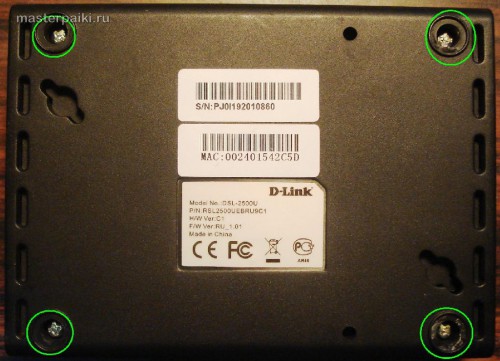
The assumption that these are bad electrolytes in the PSU of the modem, in principle, was confirmed. So, let's open the modem. We tear off the four rubber bands from the bottom and unscrew the screws.
In the next photo, there are capacitors that you should pay special attention to. They are outlined with white lines. These are 2 electrolytes of 2200 microfarads at 25 volts and one 470 microfarads at 16 volts. They are usually swollen, rubber bands are squeezed out.
If you have an oscilloscope, you can see the ripple level at the output of the 3.3 volt secondary power supply, just there there is a capacity of 470 microfarads at 16 volts.
Here is such a not very happy picture. At 3.3 volts, the ripple is about 0.5 volts. We change the capacity by 470 microfarads unambiguously.
Conclusions.
The technique is not the worst, modems very rarely die from external influences, but they are not adapted for round-the-clock work. Have worked - turn off the modem, unplug the adapter from the socket, and it is better to pull out the ADSL line.
Have you encountered a situation when the modem does not work? Regular ADSL, which provides your home with the Internet. It turned out that the modem (my home) broke down and, as usual, at the most inopportune moment!
We will talk about how to repair the modem a little later, but for now, let's say a few words about the ADSL technology itself. The abbreviation stands for Asymmetric Digital Subscriber Line - asymmetric digital subscriber line. Asymmetric because the difference in speed between incoming (to the subscriber - "Downstream") and outgoing (from the subscriber - "Upstream") traffic is quite significant here. How much? Well, if the maximum upload speed for the ADSL2 + standard is 24 megabits per second (24 Mbps), then the maximum for the outgoing one is 3.5 Mbps. Therefore, in fact, it is asymmetric.
How does ADSL technology work? The frequency range of the subscriber telephone line with the help of a splitter is divided between direct voice transmission (telephone conversation) and data transmission (Internet connection). This frequency division allows you to talk on the phone without interrupting the exchange of data on the same line.
Let's dig a little deeper: for voice transmission, the frequency range is from 0.3 to 3.4 kHz (kilohertz), and for digital data - from 26 kHz to 1.1 Megahertz (MHz). Moreover, frequencies from 26 to 138 kilohertz are allocated for outgoing traffic from the subscriber, and a band from 138 kHz to 1.1 MHz is reserved for incoming traffic.
It is interesting that the upper limit of the frequency range of a two-wire telephone cable, which is often used in the post-Soviet space (popularly called “noodles”), is 1.1 Megahertz! I would venture to suggest that this circumstance plays an important role in this whole “kitchen” with ADSL technology 🙂
Note: the ADSL2 + standard provides for an increase in the frequency on the incoming channel (to the user) up to 2.2 Megahertz.
Let's continue! I had no complaints about the modem, but at one "fine" moment something strange happened: all the light bulbs (LEDs) on the device signaled its correct operation, there was also stable operation in the switch mode, but there was no Internet! Moreover, the modem was definitely not available on command. ping and, accordingly, it was impossible to get on his web interface and look into his “soul” (in the settings) 🙂
This ADSL modem router from ZTE, model "ZXV10_H108L", did not work for me:
What is so special about this device? First of all, the fact that I got it for 1 hryvnia for the action when I connected the Internet from our local provider Ukrtelecom. As the saying goes: don't look a gift horse in the mouth! The price is symbolic, plus there is a Wi-Fi module and four Ethernet ports (no need to buy an additional switch).
So the modem is not working! Attempts to reset the device to the default settings by pressing a special button located on its back side also did not lead to anything: the modem rebooted (visually, this, again, could be seen from the LEDs), but how the whole thing did not work before , and after all the manipulations.
The photo below shows the "button" for a factory reset.
Note: A wooden toothpick is best for resetting the settings. Insert it into the hole before pressing the reset button and hold it in this position for ten seconds. The LEDs should blink, go out and turn on again - the device will go to reboot and boot already with factory settings.
The modem does not work, is it broken? We will repair it! I will not hide, before that I looked on the Internet and found out there that it is for this type of modem that there is one typical malfunction and its external signs may be different, but the result is one: the modem does not work. Now I'll tell you what the matter is.
So, first of all, we need to disassemble our device. We unscrew the bolts on its back and remove the front cover:
Remember, I wrote that I got the modem for one hryvnia? The reason why tech is cheap was immediately revealed 🙂 Apparently, craftsmen from Ukrtelecom take them, like not workers, right in China by weight, and then restore them here and distribute them to gullible subscribers, like promotional ones? How else to explain the fact that such an outrage was found under the seals ?!
Someone (history does not mention his name) has already made a working modem out of a non-working modem (soldered a capacitor). And he did it, as we can see, not very carefully, using rosin - brrr 🙂 Well, there is already one “candidate” for replacement, let's look at the others!
We completely remove the printed circuit board from the case and place it on the table:
What have I read on the Internet? And the fact that the modem does not work because of the "tipuha" (a typical malfunction typical for this product model) - two small electrolytic capacitors with a capacity of 47 microfarads and a nominal voltage of 100 Volts (47mkF / 100V). On the board, the capacitors were designated C76 and C102.
Note: You can download a small PDF file from our website and familiarize yourself with how certain components are designated on printed circuit boards.
On one of the forums, the guys advised, in order not to guess for a long time, to re-solder both capacitors. Which we will do (adding here the one stained with rosin). We wrote about how to independently replace capacitors in a separate article, so we will not repeat ourselves.
For such repairs, it is highly desirable to buy new elements (all three cost me less than half a dollar). If, for some reason, you decide to use used capacitors, be sure to check them before reuse!
So, I will repair my not working modem using a soldering station (a soldering iron with a temperature controller) and a box of tubular solder with a flux inside.We can also use a copper braid to remove excess tin after soldering and washing (isopropyl alcohol mixed with refined gasoline).
It took me about ten to fifteen minutes to repair a broken modem. Here's what happened in the end:
In the photo above, we can see three new capacitors that we installed to replace the "suspicious" ones. Now it's time to check if our "repair" was a success or not? Why did I put this word in quotation marks? The fact is that replacing capacitors, in fact, is not a kind of repair. It can rather be attributed to such a process as service electronic equipment.
Well, anyway, the modem didn't work and we took some steps to fix this situation! We connect a network cable, a power supply to our board, wait for the whole thing to load and try to ping from a home computer to our router:
Already good! Now let's try to access the http protocol and the same IP address on the web interface (web face) of our ADSL modem router:
As you can see, everything worked out! We have just repaired another device ourselves and (which is important) spent very little money and time on it. But even more important is the understanding that when the modem does not work, this is not a reason to throw it away or carry it to a service center. Some things we, as our own admins and repairmen, are quite capable of doing by ourselves!
That's all I wanted to tell you today. Who thinks about this and who has something to share regarding typical equipment malfunctions - you are welcome in the comments 🙂 Below you can watch a short video about how easy it is to replace elements by mixing refractory and hot-melt solder at the soldering point, thus lowering the temperature its melting.
Do not kick too much for the appearance - summer, heat! 🙂
Now it is difficult to imagine life without a laptop, smartphone and other benefits of a developed civilization associated with the use of information technology.
Wired and wireless networks have penetrated all branches of human activity, including manufacturing and the household level. An optical fiber line came to my apartment, which radically changed the quality of reception and transmission of signals.
However, many users still work on a simple telephone cable with thin copper conductors, while others watch only regular television and use the World Wide Web through mobile operators using 3G or 4G technologies.
For them I decided to publish this article. In it, I tell how I used to connect my home computer to the Internet via an ADSL modem and for several years used an interactive TV set-top box under the Zala tariff plan. I supplement the text material with photographs, diagrams and a video.
Back in Soviet times, I used only my apartment telephone to conduct conversations at a distance.
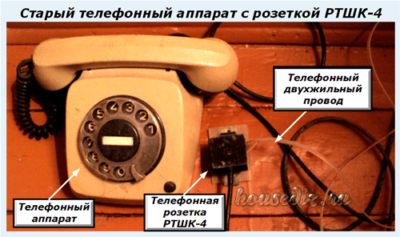
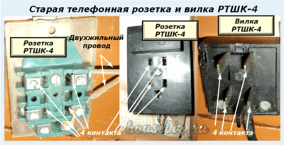
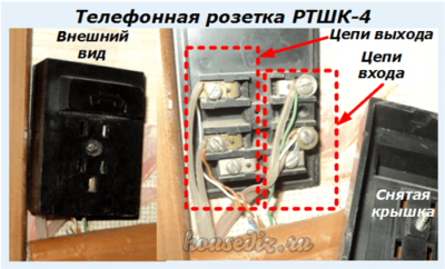
I had a device of this type on a shelf attached to the wall in the corridor, like most other people. To connect thin copper wires to the apparatus, an RTShK-4 socket was used.
In more detail, the ways to connect it are described in a separate article. I recommend that you familiarize yourself.
Then the phone was moved to another convenient place, and the socket remained on the wall. After buying a computer, it became necessary to connect it to the Internet. I used the old RTShK-4 as a transitional terminal block, having assembled the circuit on it:
- on the right side, I connected the telephone wire input circuits with a twisted-pair branch to a splitter with an additional radiotelephone;
- on the left brought the output circuits to the old telephone.
I am showing you how it all worked on the telephone line.
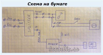
To make quick repairs, I always make sketches on paper, which I save in the case of a homemade or repaired device.They facilitate the recovery of information in memory, allow you to quickly identify faults or repeat a similar design for other people.
I have saved such a scheme for connecting a computer to the Internet and a phone to the line. I will decipher it in a more accessible language.
I made small icons of each equipment of the circuit, showed their connection with wires and cables.
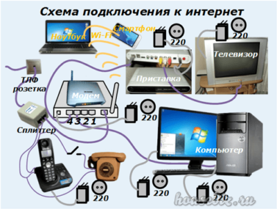
The telephone line through a copper cable comes to the socket of the telephone line. It is connected by a cable to a splitter. From it there is a branch to phones and a modem. The latter is used by a computer and an interactive television set-top box, which processes signals for watching TV.
Smartphone and / or laptop receive and transmit information from / to the Internet via Wi-Fi through the antenna of the ADSL modem.
Now a little more detail about each device.
- splitter;
- ADSL modem;
- an interactive TV set-top box with a TV set;
- two telephones of different designs;
- computer;
- TV set;
- wires, switches and connecting cables.
In appearance, it is made in a small box with three RJ-11 connectors:
- one jack is used to connect to the telephone line input;
- the other two on the opposite side face:
- ADSL modem;
- phones.
The case has the ability to mount it to the wall.
The splitter perceives two types of frequencies from the line at once:
- our voice within 0.3 ÷ 3.4 kHz;
- ADSL modem signals in the 26 ÷ 1400 KHz band.
Due to the built-in filters, they are divided into two outputs:
RJ-11 cable connectors from the phone and modem are inserted into them. This line separation allows all equipment to work simultaneously without interfering with each other.
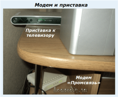
This name in the operating manual is given to the Promsvyaz M-200A modem, which has worked for me all the time without any complaints, ensuring the quality of wired and wireless Internet networks in the apartment.
The cables and cords are connected at the rear via the plug sockets:
- the far right is the splitter cable;
- the leftmost one is powered by its own block 220;
- the other four are for connecting terminal devices: a computer and set-top boxes.
The swivel antenna provides work with mobile gadgets: laptop, smartphone and other compatible devices via Wi-Fi wireless technology.
The purpose of the modem is determined from the name formed from two words denoting the execution of operations by it:
The modem works with analog values:
- converts them to digital signals when sent over a telephone line;
- or decrypts (demodulates) the digit back at the receiving end, returning it to its original form.
The ADSL designation is used for a modem operating on an "asymmetric digital line" when one-way communication is faster. Due to this technical technique, the speed of signal exchange for the Internet is significantly increased.
In my setup, an ADSL modem was used to communicate over a cable called a patch cord. It is intended for transmitting information to a computer and ensuring the operation of an interactive television set-top box.
The cable ends are equipped with an RJ-45 connector.
I explain using the example of an analog model with a kinescope, which are still widespread among the population and continue to be massively exploited. In my case, this is the Minsk "Horizon" with a prefix.
The TV signal is fed to the antenna input through the "Tulip" cable connector from the set-top box. It is located on the bottom of the front of the TV receiver, indicated by colors: yellow, white, red.
The opposite end of the antenna cable is connected to its terminals on the opposite side of the case.
The cables between the set-top box and the TV, as well as to the modem, are short. I had to place all this equipment very close on the table, which is not very convenient. I conclude that this design is not well thought out for users.
An interactive television set-top box, like a TV, works normally from a remote control.
He was chosen as the main device for conducting ordinary conversations.
Its batteries are charged when the tube is installed on the base stationary located on the windowsill. In all other cases, it can be placed anywhere in the apartment. As an experiment, I checked its work on the street, moving away to a distance of 100 meters and climbing to the roof of the building to adjust the antenna. The connection was normal.
The radiotelephone base is connected to the cable communication line through a splitter.
I use it as a backup communication device. On the Internet, you can find information that the simultaneous use of two phones can degrade the quality of the conversation. To avoid this phenomenon, I connected them as parallel lines, but the disk apparatus through switches.
Power outages do occur occasionally. When there is a power outage, you can use a backup disk apparatus to conduct a conversation or call emergency services. In other cases, such a phone is practically not needed, it is disabled.
All modern communication equipment is powered from the household electrical network. Each device needs an individual socket. Before starting the repair and reconstruction of the home wiring diagram, this issue had to be solved with the help of extension cords.
The power consumption of each unit is several watts. Therefore, the total value of the load is very insignificant: it does not create heating of wires and switching devices. Its choice should not cause difficulties, any design is quite suitable, although the decorative appearance and interior of the room is disturbed.
But in my case, all this jumble of wires and sockets is hidden behind a TV cabinet, and access to them is limited. For a stationary connection, I still recommend using an outlet block, placing it on the wall.
The photo shows power supplies for a radiotelephone (separate design), as well as a modem and an interactive set-top box. The TV outlet is located elsewhere on the wall of the room.
The ADSL modem has a built-in radio transceiver in the 2.4 GHz frequency band. The wireless Internet is created with a range of up to 100 meters or more. This is quite enough for an ordinary apartment and a private house, even taking into account the attenuation of the radiation power by the building structures or other interference.
Thanks to the Wi-Fi network, it is convenient to surf the Internet from anywhere in the apartment, use a laptop, tablet, smartphone. But for this it is necessary to "bind" them to the modem by performing certain adjustments.
The interactive television set-top box starts working immediately in the connected circuit, it does not require special setup.
Work begins with entering data into the modem via a patch cord from a computer. This process is well shown in the Inter-komp video "How to configure the Promsvyaz M 200A modem in router mode".

