In detail: do-it-yourself repair of an Audi 80 mono injection from a real master for the site my.housecope.com.
Information applicable for car repairs:
Volkswagen Passat B4 / Volkswagen Passat B4 (3A2) 1994 - 1997
Volkswagen Passat Variant B4 / Volkswagen Passat Variant B4 (3A5) 1994 - 1997
Volkswagen Passat B3 / Volkswagen Passat B3 (312) 1988 - 1994
Volkswagen Passat Variant B3 / Volkswagen Passat Variant B3 (315) 1988 - 1994
Volkswagen Golf 3 / Volkswagen Golf 3 (1H1, 1H5) 1992 - 1998
Volkswagen Vento (1H2) 1992 - 1998
Volkswagen Golf 2 (191, 192, 193, 194) 1984 - 1988
Volkswagen Jetta 2 / Volkswagen Jetta 2 (165, 166, 167, 168) 1984 - 1988
Volkswagen Golf 2 / Volkswagen Golf 2 (1G1) 1989 - 1992
Volkswagen Jetta 2 / Volkswagen Jetta 2 (1G2) 1989 - 1992
SEAT Toledo (1L)
the work procedure is also suitable for other vehicles with the Mono motronic injection system
There have already been many similar topics, but questions continue to appear. Since I have already worked out my own, I will share and let there be another one with pictures, like instructions.
I began to have periodic problems with idling, then it stalls in wet weather, then it turns gas the next day after it freezes. Yes, in fact, it's time to work out with the injection, because I haven't touched it for several years ...
We start with the coolant temperature sensor (DTOZH), remove it and use it in a "saucepan" as a can, for example, a thermometer, a multimeter, snow from the street or ice from the refrigerator, a small tile. My thermometer "shook off" and used the multimeter temperature sensor.
We take a sensor, I have one, it is 10 years old:
| Video (click to play). |
We put snow or ice in the jar so that the temperature is about 0 and take the first measurement, then turn on the tile and measure it approximately every 10 degrees right up to a boil of 100 * C. There should be about a centimeter of snow so that the metal part of the sensor is immersed and no water gets on the contacts.
My measurements:
0 * C 7.25 kOhm
12 * With 4 kOhm
20 * C 2.75 kOhm
30 * C 1.89 kOhm
40 * C 1.34 kOhm
50 * With 1 kOhm
60 * C 665 Ohm
70 * C 500 Ohm
80 * C 360 Ohm
90 * C 276 Ohm
100 * C 188 Ohm
And compare with the chart from the forum:
My testimony is close enough and what is called "will go".
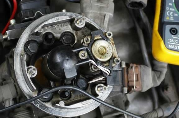
We turn to the intake air temperature sensor (DTVV), first you should check the wiring from the connector to the element ("crystal", "tablet" ...). Unfortunately, I didn't take a picture ... Both wires showed an overestimated resistance, one about 5 Ohm, the other almost 200 Ohm, which means that the conductors in the nozzle lid are acidified, and they need to be duplicated. To do this, I machined the grooves with a drill, laid new wiring and soldered to the connector pins and the element itself. Then he covered it with poxipol, epoxy, etc.
Drill:
mikantara
-
I have the same engine, but I’ll hardly be able to answer the questions.
After buying the car, I noticed an increased fuel consumption. Well, I think I still wanted to go to diagnostics.
I signed up, arrived, the car was entangled with wires, yes with testers. It turned out that the ignition was incorrectly set after replacing the timing belt. They put the ignition on, washed the nozzle, said that otherwise everything was gut, all the sensors were working.
What is the maintenance of this motor? - I ask.
This engine (AVT), they say, is no problem, all maintenance is reduced to flushing the injectors every 30,000 km. (Or once a year) with accompanying diagnostics. If the diagnostics reveals some sensors are faulty, replace them. And that's it.
Well, the rest (changing the oil, candles, filters, etc.) - like all motors.
sankalee
-
there is one nozzle on Monica! what to wash?
its diagnosed there the ebu shows the current error and that's it! no more tuning! the ignition was set yesterday almost on the distributor on the tooth skipped over. and eureka started up today.
the loss will look at the expense!
there they also say if the sensor in the air is covered, then the flow rate in the cold increases, but how to check it?
Andrey
-
firstly, you need to check the rubber gasket under the carburetor for air leaks, and secondly, the ignition with a timing belt and check the operation of the lambda probe, it seems that basically everything is about this engine in terms of gasoline consumption.
sankalee
-
25 liters is enough for 130 km! so it's not he ... but not a little
Andrey
-
It is easy to check the dtvv sensor in the manual, I laid it out somewhere, look on the forum, there is a writing of a temperature dependence graph, you will understand the resistance of the worker or not on the docks that are laid out, and the way to repair it is quite cheap, since the sensor itself changes only with the nozzle cover and it costs farm 1800 with kopecks
sankalee
-
timing belt, gum not! lamda did not look. Is it really on the monomotronics?
Andrey
-
basically, the breakdown of this sensor lies in the wires going to it, they fray, repairs are simple thrown over the top, new ones can be called by disconnecting the plug from the connector to the nozzle, there are four of them, internal to the nozzle, external to the temperature sensor
Andrey
-
Damn, how did you check the gum? start the engine, warm up and only then just swing the carburetor if the rpm floats, it means that the rubber band is replaced, the lambda is 100%, it stands on the exhaust manifold almost at the exit looking towards the hood or I don’t remember exactly at the right fender.
sankalee
-
how to correct the brain? alter? duck on moniks as such a brain there is no current error memory and there are no more settings. or is there
and checked it! rocked warmed up (first warmed up then rocked)
that the link does not work! in Google throws
that the link does not work! in Google throws
Today, on the roads of the CIS, you can find various models with an injection engine and carburetor cars. Much less common are cars with the so-called mono-injector or mono-injection, since this type of internal combustion engine is an early development, acting as a transitional solution from the carburetor to the usual injector.
As for mono injection, such a system was used in the construction of German cars in the late 80s. For example, the mono-injector is found on versions of the well-known Audi 80, the popular Volkswagen B3, etc. Also, a mono-injector is found on many models of Japanese cars. Next, we will talk about the device and principles of the monoinjection, and also consider how to set up the monoinjection system with your own hands.
As already mentioned, the mono-injector is no longer a carburetor, while it is very different from a modern multipoint injection injector. A feature of this solution is that it is based on only one injection nozzle, which injects fuel. If we compare monoinjection with carburetors, the advantages are obvious, since the monoinjector provided ease of starting the engine, reduced fuel consumption, there was no need for flexible adjustment, which cannot be said about the carburetor dosing system. Drivers with mono injection reported better engine performance while saving fuel.
The specified nozzle is installed above the throttle valve, and the atomized fuel enters directly into the hole that is present between the body and the valve. In parallel, the fuel injection through the injector is additionally synchronized with the ignition (ignition pulse). The device also uses various sensors that help to optimize the injection in relation to different operating modes of the internal combustion engine to obtain the required composition of the fuel-air mixture. The distribution of fuel over the cylinders of the engine occurs at the intake.
It should be added that certain advantages of mono-injection allowed the solution to compare favorably with the carburetor at the initial stage, while the further development of the engine power injection systems led to the rapid abandonment of mono-injection injection and its replacement with distributed injection. This is one of the main reasons why the mono-injector is less common, since at one time the system simply did not have time to get really wide and massive distribution.A significant disadvantage of the solution is also rightly considered the low maintainability and high cost of individual spare parts. Even the single injection system did not provide proper compliance with constantly changing environmental standards, as a result of which it was soon replaced by more advanced solutions.
The correct operation of the single injection system depends on the crankshaft speed, on the ratio of the volume of incoming air and its mass, on the angle to which the throttle valve is open, on the absolute pressure in the intake, etc. There is also a connection with an oxygen sensor (lambda probe). The signal from the oxygen sensor is fed to the adaptation system, which adjusts the operation of the single injection, making the necessary changes in different operating modes of the internal combustion engine. It is quite obvious that during the operation of the car, malfunctions occur in the specified system.
Taking into account the fact that the scanner cannot determine the error, it is necessary to check in turn the individual elements that may affect the operation of the mono-injector. The following breakdowns are noted in the list of faults:
Above, we have discussed the most common problems associated with a mono injector. In the case when an independent check does not work, it is better to visit a car service. Also, the mono injection system after repair, cleaning or as a result of failures must be adjusted and additionally diagnosed. Let's see how this is done using the example of a Volkswagen B3 with a mono-injector.
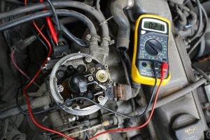
To solve the problem, you need to slightly unscrew the screw 4 on the throttle cover, after which the multimeter is connected to pins 1 and 2. Then the cover is slowly turned in different directions, recording the voltage changes on the multimeter at each displacement. By such actions, it is necessary to achieve the recommended voltage readings. As a result, a serviceable mono injection with all operable and connected sensors will function normally after adjusting and cleaning the throttle.
- 10 spanner (a ratchet wrench and a 10 head are better);
- Pliers;
- Flat and Phillips screwdriver;
- New gasket;
1 centimeter. The ring is simply pulled off the pan guide. To help us, we need a flat screwdriver. After using a Phillips screwdriver, unscrew the 2 screws on the lid, then unscrew the 7 latches in a circle and remove the pan lid.
Monoinjection is a simple thing. At least that's what they say 🙂
This is not the first year that I have been periodically bothered by dips in traction, which appear more often in damp weather. It looks as if the ignition was turned off for a split second and then turned on. There is a failure, followed by a sharp jerk. From the outside, it sometimes looks as if a kettle is sitting behind the wheel, which has not yet made friends with the clutch 🙂 And it is interesting that exactly the same behavior is observed in a friend on the same car. He has already changed everything that was possible, including a new distributor, no difference.
And, perhaps, with the exception of the engine control unit and the potentiometer, there are no old parts left in the ignition system. Until recently, it was not possible to buy a potentiometer separately. It was sold only in assembly with the lower part of the single injection, only the original and cost absolutely cosmic money about 34,000 rubles. But not so long ago, the Chinese closed this market niche by releasing a replacement for this potentiometer for a ridiculous 1600r. In general, for those to whom this topic is relevant, I made this report. First of all, we get to the mono injection by removing the air housing.
Filter. This process will not be described, it has already been done a million times. When the engine was running without the housing cover, I noticed the effect of icing on the damper. Because the air is taken from the street, and not heated from the exhaust manifold, as is done in the assembled version.
As an experiment, I put on the lid for a minute, after which I looked again there was no ice. CHTD. This effect, by the way, also torments many users of m / v (monoinjection), and it was even given the name THM or Temperature Glitch Monoinjection. But now, in fact, I'm not talking about that at all 🙂
So that's it.
We start by checking the correctness of the IAC end switch gap setting. 1) with the ignition off, remove the block from the IAC connector and supply 6V to the two top contacts of such a polarity so that the regulator stem completely retracts
2) we adjust the position of the shock absorber 1 so that when the throttle is released, the gap 2 disappears completely, after which the shock absorber is literally recessed by 1-2 mm. 3) we connect the tester set to the dialing mode to the two lower terminals of the IAC (terminals of the limit switch 3). It is very convenient if the tester in this mode is still able to squeak, so that you can determine the closure of the limit switch by ear
4) using probes with a nominal value of 0.45 and 0.
5mm we check and, if necessary, adjust the gap between the throttle stop screw and the IAC rod 4. With the correct setting, the limit switch should close when inserting the 0.5 probe, but when inserting the 0. 45 probe it should not close.
If no one's playful pens have yet managed to get to your mono injection, then most likely, after completing steps 1-2, you will have the correct IAC clearance. Now let's make a control measurement of the voltage on the potentiometer. By removing the protective rubber from the potentiometer connector, we can get a tester to its terminals. Turn on the ignition (DO NOT CONNECT IAC connector)
First, we measure the value of the reference voltage, the voltage at terminal 5. If it differs from 5V by more than 0.
2, then you should look for a malfunction in the electrical (most likely a voltage stabilizer in the engine control unit). If the voltage seems to be correct, then move on to measuring the voltage between terminals 1 and 2. In my case, it was equal to 0. 21V.Prying the caps off with a knife, remove them from the potentiometer mounting bolts and, after making marks of the current position, remove it from the bottom of the mono injection.
As you can see from the photo, my potentiometer was visually far from being in the worst shape. Just like the sliders. But while wiping the mating surface on the m / v body with a rag, I accidentally hooked the top slider and bent it slightly, then I had to painstakingly set it to its original position. Therefore, be extremely careful in this place.
The runners are VERY soft and gentle! We put the new potentiometer in its place and slightly tighten it with the bolts so that the sliders reach the potentiometer board, but at the same time we still have the opportunity to slightly move the potentiometer around the throttle axis. With the ignition on, measure the voltage
between 1 and 2 terminals and adjust the position of the potentiometer so that it is within
from 0. 18 to 0. 2 V. When the bolts are tightened, the potentiometer shifts slightly and the voltage goes away. Therefore, it must be constantly monitored and, if necessary, by light tapping, adjust the position of the potentiometer so that the voltage remains within the specified limits.
Turn off the ignition. The operation is complete. After a certain number of attempts, I managed to set it exactly to 0. 19 V. Just in case, I measured the resistance between terminals 1 and 2 850 Ohm (measured on a potentiometer with the connector disconnected).
We put on the bolt caps in their place,
connect the IAC connector, put on the rubber cap of the potentiometer connector and replace the connector itself. We start the engine. In my case, the car started up perfectly fine as if nothing had happened. Conclusion I haven't done any test trips yet, so I can't say whether the replacement helped or not. But on the twentieth century, the engine began to run smoother.
I will observe in dynamics. It is also still necessary to carry out the adaptation of the DPDZ with the help of VAG-COM, but I have not had time to do this either. Then I will supplement the post. When carrying out the work, I used a report (more complete) from volkswagen.
Msk:
UPD Drove to work. I can state unequivocal
positive result! 🙂 Smooth XX on a cold and hot engine, there are no dips and jerks, the thrust is uniform. In general, the time was definitely well spent! :).
Status:
Hello to all! So I decided to write how to install the TPDZ (throttle position sensor) on a single injection! Because topics on this issue often come up, but there is no general topic where everything is stipulated!
To begin with, this requires the following tool:
1. A tester, preferably digital
2. A set of thoraxes
3.Alcohol
4 cotton swabs
5. Analogue tester (pointer)
6.Oscilloscope is desirable
7.Stroboscope (in my case Iskra1 80s)
Problems associated with TPS: Dips when starting off, at low DZ positions (I had 9-11 *) dips in engine operation until the internal combustion engine stops (internal combustion engine), fuel consumption is slightly increased (by about 1 liter), insufficient dynamics, during adaptation DZ popped up an error of the DZ potentiometer (unfortunately I don't remember the number), when warming up, especially in the cold season (temperature -5 * and more), the effect of XX swimming was observed (not even swimming, but gassed itself, as if someone had given gas and released it), at the end, when the DPDZ already died, the unstable XX and frequent stops of the internal combustion engine, especially on a cold engine.
I want to make a reservation right away that this is all true only if everything else in the engine and electronics of the car is working properly and adjusted (timing marks, ignition is set, lamba probe (oxygen sensor) is 100% alive and its mileage is not more than 100t.km, DTOZH is working and corresponds to the characteristic temperature resistance, the IAC is operational, the candles, BB wires, the slider and the distributor cover are operational, and all consumables are replaced). Otherwise, you can make out a serviceable and innocent TPS!
A simple way to disassemble, clean and assemble for those who first read and then do!
From the beginning we warm up the car to 90 *. To measure the initial voltage 0 * DZ, for this you need to push the IAC rod to the end, you can do it in three ways:
1. Remove the connector from it and apply voltage to the top 2 contacts (for 4-pin IAC) in such a polarity that its stem moves to the end. It is desirable to supply voltage from a 6v battery, if there is no 6v source, 12v can be supplied but through a 12v 5W light bulb, it will act as a limiting resistance so as not to break the IAC gearbox. Done with the ignition off.
2. If you are alone and there is no 6c source, turn on the ignition, approach the engine from the right side (in the direction of travel) with one hand, open the DZ so that you can press the IAC end switch, at this moment IAC will move in (we press the end switch with the same hand, which we open the DZ) and then it will move out a little, so you need to catch such a moment when it has moved in, but has not yet had time to move out and disconnect the connector (respectively, with the other hand) from it, if it did not work out the first time. Let's try again, I manage to do this from the first second time!
3. Unscrew the 3 bolts for the thorax and remove the IAC.
The IAC rod is removed now it is necessary to check whether the IAC rod rests on the DZ, otherwise the voltage measurement will be inaccurate. How to check the gap and adjust after cleaning is described here.
Everything is ready to measure the voltage, the ignition must be turned on, we take a digital tester and measure the voltage between 1 and 2 feet of the DPDZ (the contacts are counted from right to left, contact 3 is absent), while we open and close the DZ several times in order to more accurately measure the voltage it perhaps it will not always be the same, then we are looking for the arithmetic mean, but it should still be very close to the voltage 0.18-0.2v + - 0.2v, if this is not so, then this method, unfortunately, does not suit you because your TPS is very worn out and you will have to make adjustments according to the second method using a computer and other means! They measured it and wrote it down on a piece of paper, otherwise you will safely forget the value while you clean it.
Now we remove the mono injection from the car.
In the walkie-talkie, how to remove a single injection: remove the corrugation from the air filter to the single injection 2 clamps, disconnect 2 hoses behind the single injection on a thicker separator on a thinner hot cold air damper (plastic fittings are neat), unscrew the snail 3 bolts for 10 keys, disconnect the gas cable , we disconnect all the wiring from the single injection (nozzle, IAC, DPDZ, hedgehog heating), we still remove the hedgehog heating wire from the single injection holder, disconnect the fuel hoses. mono injection in hand!
Now you need to measure the resistance of the tracks between different contacts as in the table and write down all the values on a piece of paper, so that you can then compare with those that will be after reading the TPS
In parentheses, the value for most of the measured ones is indicated.
If your values are higher than the maximum allowable, then your car could not work normally, which means that you are going in the right direction. I changed it to a new TPS, at the new value, everything was at the minimum values. My old DPDZ had a resistance of (1 + 4) 8 kOhm already, although after cleaning everything returned to normal, I extended the life of my potentiometer by 1 year until it dies completely.
We proceed to removing the DPDZ, unscrew the 4 bolts for the thorax, pay attention to your thorax tool must have a hole inside itself, otherwise it will not work to unscrew it.
Or carefully unscrew the TPS in place, I’ll say it’s not very convenient right away, and the state of the sliders will be difficult to see.
We open the TPS, it sits on the DZ axis and has a seal in the form of a rubber ring, we carefully lift it along the edges and remove it, shaking it along the DZ axis! We look at what we have inside, there are sliders on the DZ axis. We examine their condition, should be in perfect condition.My topmost one had such a feeling as if it had been burnt, if suddenly we also take a skin from you (preferably a grain of 2000) and gently clean it so as not to bend the petals. It is not worth bending the sliders, this will lead to a faster development of the TPS resistive layer.
We look at the potentiometer itself, is the resistive layer rubbed? We pay attention to the contacts from the connector, is there anything suspicious there in the form of cracks or loose contacts?
If the resistive layer looks decent and not too worn out, then I advise you to simply wipe the resistive layer with alcohol and put everything back together, apparently it was not Babin!
You can wipe the resistive layer with spindle oil ONLY RIP, and not flood the C1 67 oscilloscope. Or there is even a special grease for potentiometers. But for some reason, many are against lubrication, well, this is your business to each his own, I think that the effect of contact bouncing is excluded with oil, as for sure everyone has heard the volume on the old technique, you twist and rustle and crackle, there is like the same potentiometer, I did not even disassemble them when I just dug in oil and forgot about them forever. So, such a bounce of the ECU contacts, oh, how you will not like it. digitization is very fast and imagine what the ECU thinks from such voltage surges !? That's right, no good, problems begin with XX in the first place.
If, nevertheless, the resistive layer is worn out strongly, and even more so the substrate is already visible (as in the photo above), then what actions need to be taken, then simply cleaning will not help here! As I understand it is usually rubbed, for some reason the very top track. There are 2 ways to heal.
1. As I did, but it is not entirely successful all the same, because you have to be very careful and you need to understand where to bend and bend. I had the top track wiped and I had to essentially move only one slider to the layer that had not yet worked, I neatly tucked a few petals of the slider up with a thin needle, others down, while making sure that the slider itself remains at the same distance as the others. protrusion to the resistive layer. Such a repair was enough for me for a year, although, as you can see in the photo, the wear on my TPS is very large and it was like this already at the first opening, maybe quite a bit less. After that, we do what was mentioned above with the coating of the resistive layer.
2. The method is much simpler and probably has not been tested more successfully, it was offered to me by Ten70.
The bottom line is to shift the entire potentiometer vertically up or down by 0.5mm, and this will achieve a 0.5mm shift of the sliders, which is quite enough considering that there is only one slider about 2mm. Where to move the potentiometer, you need to look at each potentiometer separately, where there is more of a non-working layer relative to the worn one in the opposite direction and move it. For example: the scuff from the sliders is visible and at the top the distance of the still untouched resistive layer is greater, which means that to get to this layer the potentiometer must be lowered! Now, because the potentiometer itself sits on the DZ axis, and just don't lower it, then you need to bore the bushing in the potentiometer by 1mm in diameter so that it can move up and down by 0.5mm relative to the axis. It is better to bore the sleeve with a reamer, well, if there is no reamer, you can use a drill, I will not write the data of drills and reamers, it is possible that the axes can be of different diameters. Berm caliper measure the diameter of the axis and add 1-1.1mm, and we get the desired size of the drill or reamer. We deploy (drill) the sleeve, you should get something like this:
this is what it looks like after boring with a reamer
After that, we do what was mentioned above with the coating of the resistive layer.
That's all about the method when I read it and started doing it, and if I took it off and didn't try it on, a few points are added here.
PS. There are many articles on the Internet on how to set up a TPS but most of them require a gas analyzer. Based on what I found on the Internet and what I had from devices and tools, I did it on my own. Fuel consumption on the highway was 6.5-7 liters, urban cycle 9-11 liters.After the new TPS was installed, the flow rate did not change or changed, but this is not noticeable, i.e. it turns out that when doing what I wrote, the TPS can be adjusted using this technique. I also want to note that all the sensors were new, including the lamba, or had a very low mileage of up to 20t.km.
Special thanks to Ten70 for helping me create this theme!
| Video (click to play). |
Replenishment in my fleet))) Opel astra 1.6 sedan on iz.

