In detail: do-it-yourself repair of a car telescopic antenna from a real master for the site my.housecope.com.
Sooner or later, all things fail. Sometimes through the fault of the owner, and sometimes through the fault of the manufacturer's plant. But one way or another, in our time of permanent crises, sometimes there is simply no way to spend money on a new thing, especially since DIY repair is not so difficult. And in this article I will talk about a special case of repairing the Optim CB-2001 antenna.
In principle, I have already described this technology in an article about a fake Lemm AT-2001 Turbo, and if you haven’t read this article yet, I recommend reading it. After reading these two articles, you will know in detail how to repair a car communication antenna with your own hands.
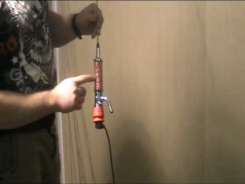
This antenna, Optim CB-2001, was sent to me by Alexey from Novorossiysk with a request to repair and return it to the air. What I actually did.
The antenna was disassembled, a separate case, a separate top cover, there was no cone into which the pin was inserted, and the upper bronze bushing was torn from its rightful place and dangled on the upper terminal of the hot coil.
Apparently, this knot loosened and the bolt simply "gnawed" through the fiberglass insulator, falling off it.
And the first thing we need to do is secure it in place. For this we use a regular cyanoacrylate-based superglue.
We put the top sleeve in place, glue it with superglue and let it dry.
Obviously this will be extremely fragile, so the next step is to reinforce the hot coil with epoxy. However, before filling the antenna coil with epoxy, I strongly recommend that you clean all surfaces of the antenna and thoroughly solder the coil. I described how to do this in the article about preparing antennas for operation.
| Video (click to play). |
We get EDP glue in a hardware store, this, in fact, is the very same epoxy.
We take out the bottles from the box.
Pour one and a half parts of epoxy resin and one and a half parts of hardener into a suitable container. One part corresponds to the volume of liquid between the marks on the surface and the label of the vials.
As a vessel for mixing epoxy components, I chose an ordinary plastic cup. The volume of resin in the photo is taken with a margin, you can take less.
After adding the hardener, mix the epoxy resin thoroughly for 5 minutes.
Before pouring the epoxy into the coil, the joints should be lightly sealed to prevent the resin from leaking out of the coil. To do this, I simply applied a little flux gel for soldering to the joints. Also for these purposes you can use the well-known LITOL-24.
We put the coil vertically, clamp it in a vice, the outer case.
In order to securely fix the upper sleeve on the insulator, pour a little ready-made epoxy into the sleeve, being careful not to get into the threads. Do not fill the entire internal volume, since after the resin has hardened, you will not be able to screw the upper cone with the pin into the antenna.
After this procedure, carefully fill the inner volume of the coil with epoxy resin. Take your time and let's get air out.
You need to fill it up to about this volume.
The final stage, we cover everything with a top cover, which will center the coil and leave it all for 24, or even better for 48 hours until the epoxy resin has completely solidified.
After that, of course, the hot coil becomes non-separable, but protected from any surprises and you can no longer worry about the safety of the antenna.
Posted by admin in Household appliances 29.06.2018 0 5 Views
Usually, DIY antenna repair is more about tuning. Radio amateurs are aware of the parameters that need to be adjusted. This is especially true for home-made devices for receiving a signal. For example, the ideal SWR is equal to one, in the descriptions of the self-assembly of the antenna you will see either an a priori calculation of this parameter, or instructions on how to adjust the dimensions and circuit using the SWR meter. This approach will allow the signal loss to be reduced to the first amplifier stage, therefore, the sensitivity of the receiving device (the range of the transmitter) increases. In practice, this means improving the quality and distance of confident capture of stations and walkie-talkies. This is important for the terrestrial antenna.
Soldering is an optional step today. Shrink wrap will help to restore the integrity of the telescopic antenna (without the possibility of folding). Take the trouble to ensure reliable contact at the fracture site. To solder steel, buy a special acid for surface cleaning.
The phrases repairing a collective antenna or repairing antennas with your own hands sound funny. These are passive devices that do not require professional maintenance. If a child breaks, repair the telescopic antenna, tin the ends, solder. Detailed instructions are not required; any man (boy) can repair the antenna on his own.
Regardless of the incoming signal, the wave is characterized by frequency and polarization. Two aspects determine the design of the antenna. The power of the incoming signal also makes adjustments. Depending on the data, the question of the required amplification is decided, whether to obtain due to directional properties or an amplifying stage.
Let's make a reservation that the sensitivity of the receiving device is the minimum signal level caught by the equipment. Of course, the lower the field strength at which a broadcast is heard with confidence, the better. The sensitivity depends on the signal loss to the first amplifier. After that, the attenuation is not so critical. For this reason, the feeder between the antenna and the receiver is tried to be made as short as possible. For the sounded purposes, the VSWR is minimized. In this case, the power goes into the feeder. The concept of matching is known, the term is closely related to the mentioned parameter. Ideally, the characteristic impedance of the devices in the circuit is the same. The antenna is manufactured in 75 Ohm, the cable is 75 Ohm and the receiver is 75 Ohm. If the link is out of line, matching devices are used. Quarter-wave transformers, U-loops, line segments.
How to increase the signal level. Take the trouble to aim the antenna correctly. The dish should face the satellite. It's harder on earth. There is a concept - a re-reflected signal. It is not a fact that the direction to the station will give maximum confident reception. The main power can come from an arbitrary azimuth and elevation angle, it is worth tormenting in search of the right solution. Outsiders to the radio are surprised why the receiver picks up better in the corner of the room than at the window, in reality it is simple - in the area of the window sill there are no trajectories of a favorable alignment of the superposition of fields. In simple terms, this means that the waves fold in incredible ways, giving an amazing picture.
A beginner does not understand this, let us explain: if at a given point in space two strong signals add up in antiphase, you get zero. A pair of weak beams can have a much better effect if the wave is coherent. If a person could see radio waves, the room would be dotted with gaps and bright places, like a playing wave of the sea reflected on a rock. The picture will not be permanent at all. Any cloud, rain, wind will affect the result. For this reason, it is far from always enough to aim and tune the antenna once for constant reliable reception.
It's easier with satellites.Tricolor TV antennas aim once and for all. The bracket is equipped with several sets of bolts for the indicated purposes. It is enough to tighten it properly to ensure the right direction for years. Note that the broadcasting satellites are geostationary. From the surface of the Earth, they seem to be motionless. This is possible when the spacecraft makes exactly one orbit in 24 hours. You will get the indicated alignment by moving the satellites above the equator at an altitude of 20,000 km. The exact numbers are not very important, the main thing is to understand that the broadcasting devices hang over the equator at the same height, there is no identical azimuth for two different satellites.
A galaxy of spacecraft writes an arc in the sky with a long-calculated shape. Therefore, it becomes possible to catch a lot of programs on the plate. To achieve the goal, an arc is set with hung emitters. As a result of the laws of reflection, each converter receives one satellite. It is important to correctly withstand the polarization (horizontal or vertical, in Russia there is also a circular one).
Many have understood where the conversation is going. There is a depolarizing plate inside the converter. Take the trouble to put it a little differently in order to change the parameter in the required direction. To receive the right polarization, the slope is 45 degrees to the side relative to the vertical axis of symmetry of the irradiator, in the case of the left polarization, the offset is in the opposite direction. The question arises, why fence a vegetable garden. There are several answers here. Some experts believe that in the Russian Federation circular polarization is accepted as a tribute to the technologies of the USSR. In the past, it was customary to build non-geostationary spy satellites. Then, with linear polarization, reception on the ground is difficult, the plane at times tilts at an unpredictable angle. The application of the circular solved the indicated difficulties - all that remained was to aim the saucer at the trajectory of the spacecraft.
The plane of inclination of linear polarization is influenced by at least two additional factors:
- The position of the satellite in the sky. It has already been said that the spacecraft are scattered in an arc. Satellites on the horizon are seen slightly tilted. It is necessary to more accurately aim the feed relative to the plate and tilt it as needed.
- The Faraday effect is known: an electromagnetic wave rotates in a constant field of the Earth. This leads to a tilt of the plane of polarization, it is difficult to calculate the choice in advance. We'll have to experimentally turn the converter while tuning the satellite dish.
Trays vary in diameter. The focal length is related to the aperture angle of the feed, otherwise the reception becomes uncertain or is eliminated. A large opening combined with a small plate looks silly. In theory, the feeds should be placed in the focal plane. Here rays that come in parallel from a certain direction intersect. To achieve the result, special guides are sold where the converters are strung.
When repairing the Tricolor antenna and tuning, it is useful to use special devices. For example, Satellite Finder. The device turns on between the receiver and the antenna, beeps more piercingly as the signal level rises, when the master rotates the cymbal to the sides. First, the correct position of the antenna is achieved, then it is the turn to adjust the position of the feeds. This is where the knowledge presented in the article will come in handy. Experimentally find the correct slope. The work is easier to do together, focusing on the satellite search program built into the receiver. The process is tedious and long, but rewarding.
Let's add about the ranges. C usually uses linear polarization, while Ku uses linear polarization. We have already talked about the Faraday effect, it is less pronounced at high frequencies. Ku broadcasts are predominantly linear. The depolarizer converts circular polarization to linear polarization, but does approximately the same with linear polarization. For the correct setting, it is important to know:
- The depolarizing plate is made of dielectric material.
- Thickness, length, shape affect the reception quality.
- The depolarizer contains steel pins that are visible when looking into the feed. There are two causative agents - vertical and horizontal.
- In order for the converter to simultaneously receive the C and Ku bands, you need to buy a combined model. It will not be possible to receive reception on a simple irradiator.
Combined antenna converters will begin to lose part of the signal, the same is observed if two are placed side by side, one per band. There is no ideal solution, it is possible to fight:
- A combined antenna feed without a plate is taken.
- A tee is cut into the feeder, feeding separately two receivers (one per band) and two TVs.
- According to the testimony of the equipment, the position of the antenna is located, where the signal is maximum.
- The selection of the material, size and position of the depolarizing plate begins. It is not a fact that the factory one will be the best option, do not forget to tilt the irradiator, as described above.
As a result, there is a chance to find a position in which both ranges appear best. This means that the repair of the TV antenna ended with a positive result.
Immediately I ask you not to kick - they say, a foreign car, buy a new one and steering wheels for service
Everything is clear, but this is already the third antenna broken on my car (respectively
each new one was bought and replaced) and I still have time to buy the next one for 50 yoy.
🙂
In addition, if we estimate that on
- search for antennas in the store
- a trip to the store
- rebirth
- replacement
it will take 2-3 hours (when replacing in the service, the same time will come out for a circle)
And I spent the same 3 hours (at a convenient time for me), saving 50 ye on the antenna
🙂
Moreover, now I would have spent an hour and a half on everything.
So there is some reason.
🙂
Symptoms - one of the antenna tubes is bent at its base where it enters
into the larger tube.
Moreover, the closer the damage is to the base of the broken tube, the less
reduce the length of the repaired antenna.
Tools and materials
1) Pliers (large). Needed for rolling
2) Side cutters. Needed for trimming the edge off end.
3) Hacksaw or roller pipe cutter 🙂
4) Flat personal file
5) Key 17
6) Key or head 10
7) Phillips screwdriver
8) Flat screwdriver (if you need to open the case)
9) 65 watt soldering iron
10) Tin
11) Liquid flux (I used aluminum flux)
12) Water resistant grease with good thermal properties
13) Rags, rags
14) Silicone sealant (acid-free)
15) Voltage source 12 volts. I used a power supply unit from an old pussy.
The battery can be used.
Please note that the current consumption can be up to 5 amperes!
16) Regular square file. Convenient for deburring the inside of the tube
DISMANTLING the antenna from cars
1) Unfasten the caps from the trunk trim to access the antenna
Put the caps in a box so as not to lose 🙂
2) Disconnect the 2-wire connector. To do this, press the latch tab.
3) Unscrew the chrome nut on the outer side of the wing with a 17 wrench
there, okuda "comes out" the antenna.
4) Unscrew with a wrench or a head 10 2 the nuts securing the antenna to
partition inside the trunk.
Put the nut and all loose parts in the box.
Please note that first you need to unscrew exactly the nut by 17,
otherwise, due to the skewing of the antenna, a certain plastic tongue will easily break
Put the nuts in the box.
Pay attention - there is a "earth" wire on the odirn of the screws
5) Remove the antenna in the trunk
6) Disconnect the drain pipe from the antenna.
7) Remove the antenna 🙂
8) Unscrew the mounting plate from the antenna
Now we proceed to DISASSEMBLY
1) Use a Phillips screwdriver to unscrew the 2 screws that secure the telescopic
pin to the plastic housing of the antenna.
Pay attention - there is a "earth" wire on the odirn of the screws
2) We take out the telescope from the plastic case.When will the telescope be
pulled out, you will see a plastic pusher in the form of a thick solid wire in the teeth
If it (the pusher) does not pull out further, then connect the ground to the black "earthen"
wire (it hangs outside the connector and ends with a round ear), and +12 apply to
BOTH contacts in the connector. In this case, the antenna will "push" the ejector out of itself.
If the antenna is fresh and you do not want to change the lubricant in it, then see the item CHINIM below.
We continue to disassemble the antenna housing
3) Unscrew all screws on the antenna housing.
4) Use a flat antenna to open the case into 2 halves
5) From the grooves of one half, clean the remnants of the sealant
6) You will see a round plastic cup. The harness of the "ejector" is hidden in it.
To remove the glass, you need to remove the washer on its axis.
7) Prying off with a flat screwdriver, remove the profiled plastic pad
8) There you will see a large gear. it can be removed if taken out
the entire tubular axis.
9) To the right of this gear (just under the telescope channel) is a small
pressure roller.
Actually, all the work of the antenna goes down to the next
1) The motor turns a large gear through a worm gear.
2) The ejector is pressed by the pressure roller with its toothed surface against
the ring gear of the large gear.
3) When rotating in one direction, this gear pushes the pusher, and when rotating
to the other - pulls inward
4) When pushed inward, the pusher goes inside the glass along the guide surface,
where and curls up into a spiral.
5) The shutdown is controlled by a small electronic unit, the wires from which
go to the motor. It is obvious that the rotation of the motor stops or when
large currents (the antenna has reached one of the extreme points) or in time (if not
a large current occurs, for example, when a pusher breaks)
Now we restore the telescope.
8) Put a ring and a brass petal on the normal end of the "broken tube".
Before that, do not forget to clean the petal of dirt and oxides. I washed in Benzine.
And we lightly process the end of the tube by 5-10 mm with a file.
Please note that it all looks like this
- tube end
- dressed petal
- dressed ring.
When everything is assembled, the ring will serve as a stop preventing the smaller tube from popping out.
from a larger one, and at the same time it will compress the petal, forcing it to unclench and improve contact.
9) now we put all this in a large tube, but so,
so that the brass petal, dressed on a smaller tube, sticks out 10-15 mm along with this
SMALLER PIPE. This is to ensure good pressure of the petal against the smaller tube.
10) We drip liquid flux onto the end of the petal (and onto the round holes) and solder
this place.
11) We rinse with water from flux residues and wipe it dry.
12) Remove excess flux with a file, restoring the roundness of the forms.
13) Lightly smear with grease, you can add a little graphite powder.
14) Now we assemble the telescope by putting the smaller tube into the larger one!
15) Check how it moves apart and moves. Hurray - everything is fine.
16) Install the brass bushing guide.
17) We make ring rolling. For this, the cutting surface of the pliers
we push the tube in the area of the koltsy groove. We constantly turn the tube.
I managed to repair it normally in 5 minutes.
In addition, I still decide to solder the seam.
BE careful - the hot bushing can melt the plastic plunger.
I felt like @ opoy and will damage 1 tooth on the pusher. But as long as it doesn't get in the way
now if only the pusher does not break there due to stress
If you have a fresh antenna and do not want to change the lubricant in the gearbox,
and did not disassemble the antenna body, then we continue to assemble the antenna
1) Insert the telescope into the outer aluminum tube.
2) Straighten 15-20 cm of the pusher and insert it into the antenna housing until it stops
teeth to the axis.At the same time, keep in mind that you need to get into the hole in the rubber shutter,
preventing dirt from entering the gearbox.
3) We supply ground to the black wire and 12 volts to 1 contact.
The gearbox starts to tighten the pusher.
4) After that, we finally insert the aluminum tube into the antenna housing
5) We fix it with 2 screws, do not forget to put a thin one under one of them
black wire from the control unit with a small eyelet.
6) Now you can install the antenna in the car in the reverse order of removal.
If you disassembled the antenna housing, then replace some of the old grease, which has become
black with dirt (although maybe it was graphite.)
Refill with new grease.
I did not change the lubricant in the worm gear and in the large gear, but simply
lubricated the toothed venez, coupled to the pusher and the inner surface
glasses, where the pusher is wound.
7) Collect all the "guts" of the reducer
8) Apply hepmetic to the half of the corpus, in which the grooves are traced
9) Let stand for a few minutes and assemble the body.
10) Go to point 1 of this "section" 🙂
In general, that's EVERYTHING!
🙂
It took a long time to write, it may be incomprehensible to read, but if you decide to fix the antenna,
then print this piece of paper - I hope it helps
🙂
It is not difficult and not so long.
Good luck and don't break the antennas!
Is your TV, radio, mobile phone or kettle broken? And you want to create a new topic about this in this forum?
First of all, think about this: imagine that your father / son / brother has an appendicitis pain and you know from the symptoms that it is just appendicitis, but there is no experience of cutting it out, as well as the tool. And you turn on your computer, access the Internet on a medical site with the question: "Help to cut out appendicitis." Do you understand the absurdity of the whole situation? Even if they answer you, it is worth considering factors such as the patient's diabetes, allergies to anesthesia and other medical nuances. I think no one does this in real life and will risk trusting the life of their loved ones with advice from the Internet.
The same is in the repair of radio equipment, although of course these are all the material benefits of modern civilization and in case of unsuccessful repairs, you can always buy a new LCD TV, cell phone, iPAD or computer. And for the repair of such equipment, at least it is necessary to have the appropriate measuring (oscilloscope, multimeter, generator, etc.) and soldering equipment (hairdryer, SMD-hot tweezers, etc.), a schematic diagram, not to mention the necessary knowledge and repair experience.
Let's consider a situation if you are a beginner / advanced radio amateur soldering all sorts of electronic gizmos and having some of the necessary tools. You create an appropriate thread on the repair forum with a short description of “patient symptoms”, ie. for example “Samsung LE40R81B TV does not turn on”. So what? Yes, there can be a lot of reasons for not switching on - from malfunctions in the power system, problems with the processor or flashing firmware in the EEPROM memory.
More advanced users can find the blackened element on the board and attach a photo to the post. However, keep in mind that you are replacing this radio element with the same one - it is not yet a fact that your equipment will work. As a rule, something caused the combustion of this element and it could “pull” a couple of other elements along with it, not to mention the fact that it is quite difficult for a non-professional to find a burned-out m / s. Plus, in modern equipment, SMD radio elements are almost universally used, soldering which with an ESPN-40 soldering iron or a Chinese 60-Watt soldering iron you risk overheating the board, peeling tracks, etc. The subsequent restoration of which will be very, very problematic.
The purpose of this post is not any PR of repair shops, but I want to convey to you that sometimes self-repair can be more expensive than taking it to a professional workshop.Although, of course, this is your money and what is better or more risky is up to you.
If you nevertheless decide that you are able to independently repair the radio equipment, then when creating a post, be sure to indicate the full name of the device, modification, year of manufacture, country of origin and other detailed information. If there is a diagram, then attach it to the post or give a link to the source. Write down how long the symptoms have been manifesting, whether there were surges in the supply voltage network, whether there was a repair before that, what was done, what was checked, voltage measurements, oscillograms, etc. From a photo of a motherboard, as a rule, there is little sense, from a photo of a motherboard taken on a mobile phone there is no sense at all. Telepaths live in other forums.
Before creating a post, be sure to use the search on the forum and on the Internet. Read the relevant topics in the subsections, perhaps your problem is typical and has already been discussed. Be sure to read the article Repair strategy
The format of your post should be as follows:
Topics with the title “Help fix the Sony TV” with the content “broken” and a couple of blurred photos of the unscrewed back cover, taken with the 7th iPhone, at night, with a resolution of 8000x6000 pixels are immediately deleted. The more information about the breakdown you put in a post, the more chances you will get a competent answer. Understand that the forum is a system of gratuitous mutual assistance in solving problems and if you are dismissive of writing your post and do not follow the above tips, then the answers to it will be appropriate, if anyone wants to answer at all. Also note that no one should answer instantly or within a day, say, no need to write after 2 hours “That no one can help”, etc. In this case, the topic will be deleted immediately.
You should make every effort to find a breakdown on your own before you get stuck and decide to go to the forum. If you outline the whole process of finding a breakdown in your topic, then the chance of getting help from a highly qualified specialist will be very great.
If you decide to take your broken equipment to the nearest workshop, but do not know where, then perhaps our online cartographic service will help you: workshops on the map (on the left, press all buttons except “Workshops”). You can leave and view user reviews for workshops.
For repairmen and workshops: you can add your services to the map. Find your object on the map from the satellite and click on it with the left mouse button. In the field “Object type:” do not forget to change to “Equipment repair”. Adding is absolutely free! All objects are checked and moderated. A discussion of the service is here.
No one will argue that high-quality reproduction of radio signals by your car radio directly depends on the correct choice and installation of the antenna for the radio station.
In addition to operating parameters, the choice of antenna is also influenced by the car owner's preferences for the aesthetics of his car, loyalty to a particular brand, and many factors that are incomprehensible to others. Yes, and of course, the challenge facing the car antenna.
If, in addition to listening to your favorite radio stations, you are going to watch TV programs in your car, then you simply cannot do without a car TV antenna.
If you limit your connection with the air only to a car radio, then the choice of the type of car antenna is exclusively your choice. Roofing felts it will be an internal antenna, roofing felts an external automobile antenna - it's up to you. And we, in turn, will conduct a short review of outdoor car antennas in order to try to facilitate your choice.
Any receiving antenna, including a car antenna, is a device that receives the energy of an electromagnetic field and converts it into electrical signals amplified by a radio receiver.And so, we are already listening to "Russian Radio" or "Chanson", for example.
Most of the car roof antennas are passive. What does it mean? Passive antennas are not equipped with a structural amplifier, they are connected directly to the radio receiver and do not need a separate power source.
The positive features of passive outdoor car antennas include design simplicity and high sensitivity.
The negative features can be safely attributed to exposure to external influences, both natural and mechanical, large sizes, and low reliability of this type of outdoor car antennas, such as telescopic (retractable).

