In detail: do-it-yourself repair of an autonomous siren from a real master for the site my.housecope.com.
Generators in the schematic are marked with a yellow border. The first G1 sets the frequency of the tone change, and the second G2 is the tone itself, which smoothly changes on the VT1 transistor connected in series with the resistance R2. To select the required sound, you can use trimming resistors of the same values instead of resistances R1, R2.
When the supply voltage is turned on, the sounder starts to generate a tone acoustic signal, the pitch changes from high to low and vice versa. The signal sounds continuously, only the tone of the sound changes, which switches at a frequency of 3-4 Hz.
In the siren circuit, two multivibrators are used on the D1.1 and D1.2 elements of the K561LN2 microcircuit, which controls the tone, and a multivibrator on the D1.3 and D1.4 elements of the same microcircuit, which generates tones. The pulse frequency generated by the first multivibrator on elements D1.3 and D1.4 depends on elements C2, R2 and C3, R4. It is possible to change the pulse repetition rate, and hence the tone of the sound signal, both with resistances and capacities.
Suppose at the initial moment at the output of the multivibrator at the elements D1.1 and D1.2 there is a logic-one level. Since a plus is supplied to the cathodes of the diodes VD1 and VD2, the diodes will be locked. Resistances R4 and R5,, do not participate in the operation of the circuit and the frequency at the output of the multivibrator is minimal, a low-pitched signal sounds.
As soon as the output of these elements is set to a logical zero, the diodes VD1 and VD2 will open and connect the resistances R4 and R5. As a result, the frequency at the output of the multivibrator will increase.
| Video (click to play). |
Further, the pulses are fed through two inverters D1.5 and D1.6 to transistors VT1-VT4, which amplify the signal supplied to the high-frequency dynamic head.
The KT815 transistors used in the circuit can be replaced by KT817, and KT814 by KT816. Diodes - KD521, KD522, KD503, KD102.
The following device can be used as an alarm or horn for a mountain bike. It is a two-tone siren and consists of a clock generator on the elements DD1.1-DD1.3, two tone generators (the first on the elements DD2.1, DD2.2 and the second on the elements DD2.3, DD2.4), a matching stage with power amplifier on element DD1.4 and transistor VT1.
The supply voltage of this circuit is from 9 to 12 volts, the speaker coils must have a resistance of at least 16 ohms, or you can use 2 3GDSH-2-8 speakers of 8 ohms connected in series.
Almost any low-power corresponding conductivity is suitable as transistors, for example, KT3102E
The circuit consists of two generators. The first is used to generate a tone, the second to change and modulate.
For the maximum volume level, it is necessary that the piezoelectric element receives a frequency equivalent to its resonant frequency in a bridge circuit.
The basis of the design is a powerful multivibrator 4047, which operates in an unstable mode. All this is controlled by a powerful MOSFET-transistor VT1, which is controlled by the NE555 timer, by generating the corresponding low-frequency square-wave pulses, as a result of which the sound of a fire siren is simulated. Switching operating modes continuously or intermittently is set using a toggle switch.
Pins 10 and 11 of the 4047 microassembly provide antiphase signals, the signals from which drive the bridge on four MOSFETs. To obtain the maximum volume, that is, to set the resonant frequency of the piezoelectric element, a trimming resistance R6 is added to the design.
Moreover, the volume level depends on the amount of light falling on the photosensitive resistor.
This circuit is made up of a combination of a musical synthesizer on the UMS-8-08 microcircuit with a powerful output stage of an electronic siren. To start the circuit, a relay is used, the winding of which is galvanically isolated from the rest of the circuit.
The UMS microcircuit has a standard connection diagram. Three push-button switches S1-S3 make it possible to configure the microcircuit to play one of the melodies. When you press the first button, the melody starts playing, and by pressing the third you can cycle through the melodies and select the one you want.
A selection of several siren circuits on PIC microcontrollers
Sat 25 Aug 2012
 Category: Auto electrician
In conferences, there are often questions about the types of sirens, their interchangeability and connection. This article has laid out some thoughts on the topic of simple sirens, in the hope that it will come in handy for someone when installing or replacing a siren. It is very important: when connecting the mass of the siren, it is advisable to always use a welded standard bolt or nut on the body.
The big drawback of these sirens is that, having cut the wires, the siren becomes silent, as in the case if the battery terminal is removed or it is discharged.
But there are also advantages - these sirens can be compact and do not require maintenance, which means they can be hidden in inaccessible places. It is convenient to install such sirens as additional ones, to replace standard stand-alone sirens with them, or to install them secretly in the passenger compartment.
Of course, there is an exception, Medalion type Clifford sirens or the like, which is a speaker. But they are disabled in a similar way.
If your siren has a lot of tones, then the number of tones can be reduced to one or you can choose the ones you like. On some models, there is a window closed with an elastic band on the body of the siren, under it there are six jumpers - their removal of jumpers turns off the corresponding siren tone, later models have jumpers on the board in the form of wires or printed conductors, cutting of which leads to similar results.
Usually the consumption of such sirens does not exceed 2A.
Any simple sirens are interchangeable. They can also replace stand-alone sirens with the appropriate connection, depending on the control signal.
The defects encountered in these sirens are manifested in the form of a quiet sound or its complete absence.
The performance of the siren is checked by sending a signal (+) from the terminal of the standard battery to the red wire of the siren, in this case the second wire of the siren must be reliably connected to the vehicle ground. If the siren is controlled by a ground signal, then applying this signal to the black wire of the siren, while the second wire must be securely connected to the (+) battery terminal using a fuse.
Note that the siren ground wire is always black, and the signal control wire (+) can be of a different color, for example, white as in Scher-Khan alarms.
If the siren started working when a signal was given, then the malfunction consists either in a break in the control wire from the alarm, or in the failure of the control transistor. The integrity of the wire is checked by applying a control signal to the wire directly coming from the alarm connector.The health of the transistor is checked with a probe consisting of an LED and a resistor. With a positive control signal, a 1kOhm resistor is connected in series to the alarm output to the siren, the LED anode (in the form of a triangle shown in the diagrams) is connected to the resistor, the LED cathode is connected to ground (in the diagrams, it is represented by a dash). With negative control, the cathode of the LED is connected to the alarm output, the anode to the resistor, and the other terminal of the resistor to the positive terminal of the battery. If the output transistor is working and the panic signal is turned on, the LED should light up.
If the siren does not work with a direct control signal, then the cause of the malfunction lies in the siren itself. This can be a break in the speaker coil, failure of the transistors of the output stage of the siren or the tone shaping circuit. With a quiet siren signal, the output stage may partially burn out, or water may enter the siren's reflective deflector. The last reason is eliminated by drilling a small hole in the siren deflector.
It is very important: when connecting the mass of the siren, it is advisable to always use a welded standard bolt or nut on the body.
Standard stand-alone sirens.
We call them standard to distinguish them from the sirens of the Clifford, Cobra, Sikura and others. The difference between autonomous sirens and those described in the previous article, in the presence of a service key and a built-in battery, as well as four wires for control and power supply.
Disabling an autonomous siren with a key does not mean disabling the alarm and its interlocks, with the exception of specific sirens and monoblock alarms. The last two types are distinguished by the presence of more than four control and power wires.
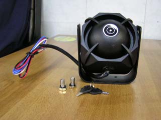
There are always red and black wires, they are respectively connected to the battery positive and to the vehicle ground. With the mass it is clear, this was said at the very beginning. The plus is connected to the signaling supply wire and as close as possible to the connector. Let me explain why. The first - the siren will be protected by a fuse, the second - if the alarm harness going under the hood is cut, the autonomous siren will immediately turn on the signal due to loss of power (provided that it was turned on with a key).
There are still two wires left, which raise questions - where to connect them. Please note that when checking the siren, namely when connecting plus and mass, it does not scream, and regardless of whether the key is turned on or not. These two wires serve for the siren to scream. Usually they are signed with a "positive trigger" - a positive trigger and a "negative trigger" - a negative trigger. One of these wires is connected respectively to the signaling control wire. If in the "Panic" mode a signal (+) appears on the wire, then a positive trigger is used, and if the signal is ground (-), then a negative trigger is used. With such a connection of the siren, the main consumption goes through the power cable from the battery, and only low-current control from the alarm. And in this case, you can connect, if desired, an additional simple siren.
Some kind of autonomous sirens, of course with a proviso, can be cited as the fact that there are sirens, even with the key turned off, when a control signal is given, they can scream. Others must be included with a key.
The advantage of these sirens, as mentioned above, is that, having cut the wires, the siren continues to scream at the expense of its own battery. Of course, she screams a little more quietly, but this does not make it easier for the hijacker. And with a good internal battery, it can scream for quite a long time, although at night five minutes will be enough to perform its function. It is advisable to check the state of the internal battery of the siren from time to time by disconnecting the terminal of the standard battery or removing the alarm fuse when the siren is turned on with the key, so that this advantage does not turn into a disadvantage.
About the disadvantages.Since there is a key and a lock, it means there must be access to the siren, and at the same time you cannot hide it far. The internal batteries of the siren can be destroyed while the siren turns into a simple one from an autonomous one, or worse, it starts to consume an increased current, thereby discharging the standard battery.
You can check the serviceability of the siren and the output stage of the alarm using the method described at the end of the article on simple sirens. The only difference is that the power on the red wire must be present, and the control signal is fed to the corresponding input to check the siren's performance. It remains to add only that a malfunction of the siren lock is possible, which sometimes crumbles or collapses, which makes it impossible to either turn on or off the siren.
To test the sirens performance - the conductor with point "A" is the place where the control signal is sent. The verification method is described in the article about ordinary sirens. A prerequisite is the presence of power and ground on the siren wires.
A) Connection of a siren with positive alarm control. The dotted line shows a possible connection of an additional simple siren.
When replacing an autonomous siren with a simple one, according to the scheme at point "A", the control from the autonomous siren is disconnected, and the simple siren becomes the main one. Insulate the power supply wire of the autonomous siren.
B) Connecting a siren with ground signal control. The dotted line shows a possible connection of an additional simple siren.
When replacing an autonomous siren with a simple one, according to the scheme at point "A", the control from the autonomous siren is disconnected, and the simple siren becomes the main one. Insulate the power supply wire of the autonomous siren.
C) Connecting an autonomous siren with protection against disconnecting the alarm connector. The diagram shows two options.
The first one is using a standard connector. If there is an unused wire in the connector - for example, a positive trigger of doors or an output to an additional channel, then by cutting off the printed conductor, you can solder the hinged jumper inside the board. This contact will become the power supply wire for the autonomous siren, and in case of power failure, the siren will turn on due to the built-in battery.
The second option is if a wire is soldered to the power contact inside the alarm and brought into the alarm harness, then the same result is obtained when the wire is broken or the connector is disconnected.
Likewise, you can protect the mass controlled siren.
D) Connection of several sirens.
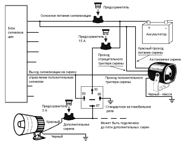
Using this scheme, you can connect several additional simple sirens, hiding them, for example, in the cabin, trunk or in hard-to-reach places under the hood. Fuse 15 Ampere - is the main one for powering additional sirens, the relay decouples the current alarm output. Three-amp fuses for each of the add. sirens are needed if the hijacker finds a siren and closes the wires, the lower fuse rating of this siren will burn out, and the rest will remain working. In an emergency, the general fuse can be switched off.
Because the power of the autonomous siren is taken from the general power supply of the alarm, then in this case it can also be protected according to the scheme (B).
Sirens, it is an important element of the car alarm. The siren serves to scare off intruders and attract the attention of people around and the owner of the car. Therefore, the volume of the siren is of no small importance, the louder, the greater the psychological impact. Loudness is measured in decibels, the higher the value, the more sound pressure the siren creates. The volume of modern sirens ranges from 90 to 120 decibels. Body shapes vary, but they are all made of durable, heat-resistant plastic that mounts to the vehicle body. You can read about the installation of sirens here at the end of the article.
12 volts - for cars and 24 Volts - for freight.
The siren may look like a regular siren, but if you connect it to 12 volts.then we will not hear a loud click and no more sound. I want to note that you need to apply voltage for a short time, otherwise it will burn out completely.
These sirens are used in alarms, which themselves create (modulate) the sound signal, and the siren is essentially a speaker wrapped in a siren case and reproduces it. Usually, the wires of these sirens have the same black color and are connected at one end to a constant plus through a fuse (no matter what), and the other to the corresponding alarm output.
Such control of the siren allows the alarm to quickly change the volume and tone of the signal. For example: The signals of arming and disarming are quiet and pleasant, and in case of an alarm they are shrill and loud.
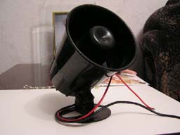
This is the most common common siren used in the bulk of alarms. This siren has two wires for connection: Red +12 Volt is connected to the alarm output, Black -12 Volt is connected to the car body. If you mix up the wires, then there will be no sound, but the siren will not burn out, it has protection against such cases.
When voltage is applied, the siren starts to emit a characteristic sound of a car alarm. The siren sound can be different: one-tone (mostly), two-tone, Six-tone, or any other. It depends on the circuitry inside the siren.
Some sirens with a short-time voltage supply (arm or disarm) give a reduced sound level, and with a longer one (alarm) after 2 seconds they increase to the maximum possible.
There are sirens with increased power and in order to avoid the failure of the output alarm trigger, connect according to this scheme using an additional relay.
A microprocessor siren is practically a siren with internal modulation, with the difference that it can be programmed by choosing signal options from a variety of options stored in the siren memory, as well as record your own melody. The siren has two wires for connection: Red - + 12V - to the alarm output to the siren, Black - to ground -12V.
For example, consider the FALCON SM-100 microprocessor siren. The siren's memory contains 39 melodies, one of them can be changed (programmed a melody of 32 notes.), As well as in addition to selecting or recording melodies, you can select Four colors of the sound of notes for all melodies. The siren is programmed by means of two buttons in the siren body.
Download manual for Microprocessor siren FALCON SM-100
Mini Siren Crime Guard AU76MP Psycho, This compact siren emits two different tones, as if two sirens were activated at the same time. You can choose between a loud signal and a muffled chirp, and it is also possible to select a sound when arming / disarming the alarm.
It is practically a siren with a built-in signal modulator, but it also has a built-in 12V battery and a lock with keys which you can turn on or off the autonomous power supply. Such a siren usually has four wires for connection.
- black wire - minus 12 volts (car body)
- Red wire - constant plus 12 Volts
- Blue wire - turning on the siren by minus 12 Volts
- White wire - turning on the siren with a plus of 12 Volts
If the siren is on, the loss of voltage on the black or red wires will trigger the siren, in other words, if the intruders disconnected the car's battery or tore off the siren, it will continue to “scream” thanks to the built-in battery. The blue and white wires can be controlled in parallel independently of each other.
For example: The alarm controls the siren plus and does not have a warning security zone. We connect the white wire of the siren to the siren control output, and the warning output of the shock sensor to the blue wire of the autonomous siren. As a result, with a light blow, the siren will briefly "warn" that the car is under protection, do not go!
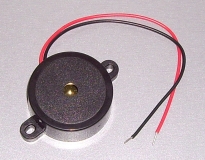
The basis of the Piezo siren is a piezo-ceramic element, which creates a high-frequency sound in the range of 2.5 - 3.5 kHz, reinforced by the horn structure of the siren. Piezo sirens have a powerful psychological effect and, with prolonged exposure, a headache is provided, and if it is placed as an additional siren inside the car, the siren's shrill “scream” becomes almost unbearable for the intruder. For example, the StarLine JP1 piezo siren has a small size and powerful sound and can be used as a salon siren.
The siren has two wires for connection: Red + 12V and Black -12V and connects like a regular siren.
Piezo beeper it is practically a miniature single-tone piezo siren. It is mainly used in immobilizers for sound messages to the driver about the state and processes occurring in them.
I sometimes use a beeper to confirm the closing and opening of the car's central locking system. We connect the beeper as follows. This is the case when the car has door control with a key and has a factory alarm, but does not have arming and disarming confirmation signals, and the owner wants to hear whether the locks have worked or not. Sometimes I use it as sounding the warning zone of the microwave sensor. Probably many were fed up with the constant “blathering” of a car standing under the window, and in order to save the nerves of others and still warn a person who came close to the car that the car is under protection, I use a piezoepper connecting it according to this scheme.
The electro-air rotary siren is a powerful siren with an electric motor that spins the siren rotor to create a high-speed air stream, which, thanks to the special design of the stator and rotor, is interrupted, creating a powerful, roaring sound.
You cannot connect such a siren directly to the alarm, you need to use a relay. The relay coil is connected to ground with one end, and the other end to the alarm output to the siren, and already through the relay contacts we transfer + 12V to the positive wire of the rotary siren, the second wire which is connected to -12V (ground) - here is the diagram.
An example is the Electro-air rotary siren PS324 by Al Khateeb with 12V power supply.
The requirements for installing a siren are quite simple in theory.
- Install a siren under the soot space.
- The siren should be installed as far as possible from the heating elements of the engine.
- The horn of the siren must face downward to prevent moisture accumulation inside the siren.
- The negative wire of the siren can be connected to the body, next to the siren, or to any ground wire, both under the hood and inside the passenger compartment.
- The positive wire is connected to the siren control signaling output. It must have good insulation to prevent rubbing from friction during vibration during vehicle operation, and must not sag in order to avoid getting into the moving parts of the car engine.
Sometimes you have to drill a metal bulkhead between the passenger compartment and the engine. If you decide to drill a bulkhead, make sure you don't drill any tube, cable, or anything else. Here the saying “measure seven times, check and drill once” will be what you need.
When you screw the siren to the metal case with self-tapping screws, make sure that in this place on the other side of the metal there is no wiring harness and no block is attached. I have seen drilled blocks and broken wires in the bundle.
The ideal setting is when the wiring is disguised as factory wiring, and the siren is hidden and not visible.In this case, an attacker opening the hood will not be able to immediately turn off the siren and this can become a turning point in an attempt to steal a car.
When the alarm gives a plus to the siren control wire, relay P1 is activated and closing the K1 contacts through which 12 volts is supplied to the siren or several sirens. According to this scheme, you can connect up to 5 or more sirens. You need to connect in parallel - plus to plus, minus to minus. 12 volt power supply apply to the relay contacts through a fuse from 5A to 20A, depending on the power of the siren or the total power of all sirens.
If you already have a siren and you want to add another one to the salon or an additional siren under the hood, then you can connect it according to this scheme, you cannot connect it without a relay, this can spoil the alarm output to the siren.
This scheme works if the car blinks with turn lights at the moment of closing and opening of the central lock from the key remote control. If not, then a different circuit is needed.
When the ignition is off, there is a negative potential on the ignition wire, sufficient for the relay to operate and even the beeper itself. When the ignition is on, the mini siren will not respond to opening and closing the central lock. The circuit can be simplified by connecting a piezoepper instead of a relay, observing the polarity (+) to diodes D1-D2, (-) to D3.
For many alarms, along with disarming, the sensors are turned off and the sensors are ideal for this scheme, but there are alarms in which, even after disarming, the sensor remains in working condition and continues to respond to the impact, then the connection needs to be changed, otherwise it is mini the siren will continue to "beep".
Even the most primitive signaling has an output for blocking by normally closed contacts. After arming, a negative voltage appears on this wire, and after disarming it disappears. We use this output, connect the negative power supply of the sensor to it, but through the diode with the cathode in the direction of the signaling.
For everything to work correctly, you need to take two diodes, connect them with cathodes together and connect them to our blocking wire. We connect the negative power supply of the sensor to the anode of one diode, and the blocking relay is connected to the anode of the second diode.
Msvmaster - Installing and disabling car security systems.
Somewhere in 20 cm from the siren all connections. The inside is never connected. Can it be enough to unscrew the screws without removing the siren and ruin the battery terminal?
It costs 150 rubles. It is expensive? I have them for free, 10 jokes lying around do you want to give?
Zero will never be. I do not mean the siren, but in general the quiescent current of the car. It should not exceed 50 mA in the place with the signaling, or it is 0.05 A.
Thank you all for the answers, I understood how to find the connection point:
Quote: “Somewhere in 20 cm from the siren all connections. Can it be enough without removing the siren to unscrew the screws and break the battery terminal? "
By "zero" consumption, I naturally meant only the consumption of the siren itself. By the way, after falling asleep, the car (measured after 1 hour), the total current consumption = 25mA. Conditions: the car is closed with its standard remote control for double blocking, the Stalker is not armed.
About replacing with a new on-line is not so simple!
Now the power supply of the siren (probably?) Comes from the AB of the car, and the sound on the siren comes from the Stalker via the trigger control wire.
And the non-autonomous will have to be connected in a different way - to hook its main supply wire to the Stalker output, or through an additional relay controlled by the same Stalker. In short, there will be a lot of alterations. It's just that the output load capacity of the Stalker at the output to the siren is 1.5A (max), so just powering a new on-line siren from this output is dumb, the consumption of the siren when squeaking can be 2A !?
When the siren is working, there are no 2A.
All signaling devices have 1.5A at the output to the siren. Not one has died yet. The relay is required if you connect horns instead of a siren. Here klaxons hawala up to 10A.
Correctly said, connecting a regular siren, we just do not use + 12V, and that's it.
Thanks to everyone who answered. I decided to disassemble my Starline SB-21. Here's what we have, maybe it will lead someone to new thoughts about autonomous units, especially installers :-)
Battery NiCd 6V, 60mAh - skewed, there are traces of some kind of electrocorrosion. When you try to squeak from him, his spill immediately drops to almost 0V, when charging, his spill goes almost immediately to 8V or more. In short - in the trash. The service life is roughly 1.5 years! Who cares, the conditions for charging it are written on the case: 14h with a current of 6mA. Now about the quality of manufacture of Starline SB-21. There are traces of water ingress and electrocorrosion on the board. The halves of the body are connected with 2 self-tapping screws (not 4!) Without any seal with an elastic band or sealant! An electrolyte with a temperature range of -40 is installed on the board. + 105C for an operating voltage of 25V - well done for that, they didn't save!
The connection of the wires of the siren and the signaling unit is made by UgonaNot by twisting, not soldering. The twisting is very high quality! The joints are wrapped with electrical tape and laid in a corrugation, all this was done with high quality, thank you guys.
What I finished. The dead battery dropped out, cut off the wires from the lock. I passed a sealant along the seam of the connection of the two halves of the case. I filled in hot glue the lock on the siren body and the head of the self-tapping screws holding the halves of the siren body. In short, sealed.
I connected my siren, which had already become non-autonomous, back in the same way as it was: the red siren - to + 12V (through the fuse!), The trigger white wire of the siren - to the signaling output. Black is the case.
Summary. Do not use stand-alone sirens unless absolutely necessary! Look in the internet for an article by the respected Kondrashov, where he has about the same conclusions.
The siren is standard equipment for security or warning systems. Designed to generate a sound signal in the most sensitive range of the human ear. Thanks to this, the sound of the siren is captured at a considerable distance from the source.
Sirens are classified according to the following differences:
- the principle of sound generation;
- supply voltage;
- the degree of sound pressure;
- type of connection and power supply.
Some of the varieties will be discussed below.
The operation of sirens is based on two principles of sound effect formation:
Sirens can be divided into wired and wireless according to the method of communication with the control unit. The latter receive a signal to be triggered by a radio channel of various frequencies.
Wired and wireless devices can have two power options:
- from the main source of energy - a car battery or a standard network in the premises;
- self-powered from its own source (accumulator or batteries).
Making a talking siren is shown in a video from the Tver Garage channel.
One of the ways to improve the siren is to change the tone of the sound. This is achieved by transforming the resistance of the resistor on the sound generator controller board. With an increase in resistance, the frequency of the sound decreases, and with a decrease, it rises. The selection of resistance is carried out empirically.
To make a multi-tone musical siren yourself, you will need knowledge in circuitry and the ability to independently make printed circuit boards. To record melodies into the memory of the generator microcircuit, you will need a programmer (for example, PIC K150). In addition, you will need to buy components in accordance with the diagram.
- Draw a schematic of the printed circuit board in Sprint LayOut.
- Print the template on glossy paper.
- Apply the template with an iron to the textolite with a one-sided layer of foil. It is recommended to sand the surface with 1000 grit sandpaper and degrease it.
- Remove the paper from the blank (by soaking in hot water).
- Etch the workpiece in ferric chloride solution.
- Drill holes for component mounting.
- Install the elements in accordance with the diagram.
- Place the resulting sound generator in the alarm box.
- Assemble the case and install the siren on the car.
It is possible to create a multi-tone siren using a digital microcircuit such as 561LN2. The basic plan includes two sound generators, indicated in the diagram - G1 and G2. Generator G1 determines the frequency of sound vibrations, and G2 - the tone. The transistor VT1, connected in parallel with the additional resistance R2, is responsible for changing the tone. Resistances R1 and R2 can be used as a fixed value (33 kOhm) or adjustable. By adjusting, you can achieve a change in the tone of the sound.
Siren circuit based on 561LN2
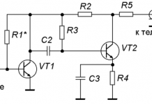
A siren with an operating voltage of up to 12 volts can be built on the basis of two transistors and a speaker with a resistance of 16 ohms (or a series connection of two speakers of 8 ohms). The diagram of the device is shown below.
If desired, the car owner can create a two-tone siren based on multivibrators. When turned on, the sound generator (microcircuits D1.3 and 1.4) creates an acoustic signal, the tone of which periodically changes from low to high (control is carried out similar to D1.1 and 1.2). The tonality is regulated by the resistances available in the circuit.
Two-tone siren on K561LN2 diagrams
The low tone is adjusted with R2 and R3, and the high tone is adjusted with R4 and R5. The frequency of the change of tones is set by the resistor R1. The parameters of the C2 / R2 and C3 / R4 elements must be identical, since the duration of the positive and negative drops on D1.3 and 1.4 depends on them. When a positive signal appears at outputs D1.1 and 1.2, the diodes VD1 and VD2 are closed, which cuts off the resistances R4 and R5 from the circuit. Due to this, a low-tone signal is generated.
The main element of the siren is the K561LN2 microcircuit
If there is a negative signal at the outputs D1.1 and 1.2, then the diodes connect the resistances R4 and R5 in parallel with R2 and R3. Due to the change in resistance, the key goes high. Signals of any tone are fed to amplifiers D1.5 and 1.6, and then through the transistor output VT1 / 2/3/4 - to the speaker, designated - BF1.
On the basis of the UMS-8-08 microcircuit or similar, you can build a siren with increased power and switching on using a relay. The siren is capable of operating at voltages up to 15 Volts and is suitable for installation on cars. To turn it on, it is enough to send a signal to the input of relay P1, for example, parallel to the lamp circuit of the plafond in the passenger compartment.
To adjust the microcircuit, use the S1 / 2/3 buttons (iteration over the melodies stored in the memory). When the relay contacts are closed, voltage is applied to the circuit, and the sound signal is turned on. The UMC-8-08 is powered through the R3 and VD1 circuit (the voltage is stabilized up to 3.3 V). The signal from the VT1 collector is fed to the D2.2 and 2.3 microcircuits. Moreover, it enters the first immediately, and the second through the additional inverter D2.1. Due to this, at the outputs D2.3 and 2.4, antiphase pulses appear, which are fed to the transistor bridge VT2 / 3/4/5. When the positive half-periods on D1 and D2.3 coincide, current flows through the VT3 / 4 transistors to the speaker in one direction. With a negative half-cycle, the direction of the current changes. This achieves a loud sound. The circuit uses a relay of the RES-10 type and a quartz resonator for a frequency of 32768 Hz.
For the speaker, it is recommended to use a device with a plastic cone with increased strength.
A failed siren can be modified in accordance with the diagram below. It is based on the KA2410 chip from a cell phone call. The signal is amplified by a transistor and fed to a speaker. A protective diode VD1 is installed at the input, which protects the circuit from incorrect connection (supplying a negative voltage to the positive input).
Siren based on a chip from a cell phone
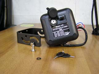
The autonomous car siren can be powered by the built-in power supply or by the main battery. The choice of the type of power supply is carried out by turning the locking mechanism located on the back of the case.The lock cylinder is connected with contact groups that use one or another power circuit.
One of the models of an autonomous siren common on the Russian market is Pandora DS-261 with a power of 20 W and a sound pressure threshold of 115 dB. The siren is compatible with all burglar alarms (Pandora, Starline, Scher-Khan and others) and is sold for up to 500 rubles.
Siren Pandora DS-261 with switch lock
The DS-261 siren has a wiring harness with four cables for connection, but only three wires are used during the connection process.
Siren connection schematic diagram
Installation sequence:
- Install the device on the car. It is recommended to install the siren on the engine shield away from the exhaust manifold and ignition system wiring. The installation site must not be flooded with water. When choosing a location, it is necessary to exclude access to the siren from under the car.
- Lay the connection wires and connect them according to the indicated diagram.
- Connect the red wire to a constant supply of +12 V from the main source.
- Black wire connect to car body (-12 V).
- The white conductor receives a positive control signal from the alarm unit. In the diagrams, this wire can be designated - "positive trigger".
- The fourth blue wire ("negative trigger") is used to control the siren by a negative signal. It is recommended to cut it off or carefully roll it up and lay it on the base of the siren.
- Turn the key to the position with the green dot. In this mode, the siren will automatically enter the alarm state after power failure from the main battery.
Autonomous sirens from other manufacturers are connected in a similar way.
Several schemes for installing autonomous and non-autonomous sirens can be used on cars:
- If the car owner decided to convert the warning system from an autonomous siren to a conventional one, then he may be faced with two connection options. When installing a conventional siren instead of an autonomous one with control by a positive signal, it is necessary to connect the power of a conventional device to the control wiring. The autonomous siren cable cut at point "A" is insulated. The second wire of a simple siren is routed to the body.
- If the autonomous siren was controlled via the negative wire, then the regular siren is connected according to a different scheme. The negative terminal is connected to the negative trigger wire, and the positive terminal is connected to the power supply wire of the stand-alone device.
- To provide protection against disconnection of the connector of the main alarm key fob, it is necessary to upgrade the block. An additional jumper is installed inside the printed circuit board. When the plug is disconnected from the unit, the autonomous siren will turn on and work from its own battery.
- Sirens of different types can be simultaneously used on one alarm system. The non-autonomous signaling device is connected via an additional relay and is protected by a separate fuse. In total, up to five sirens can be installed in parallel.
Installation diagrams are shown below.
| Video (click to play). |
The author Alyosha Popovich changes the usual siren to a six-tone one.

