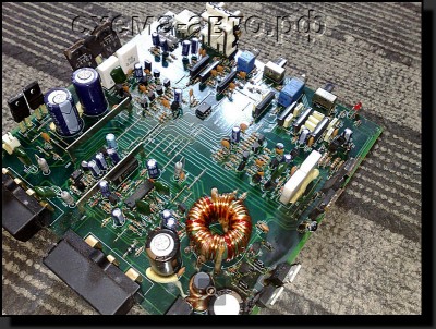
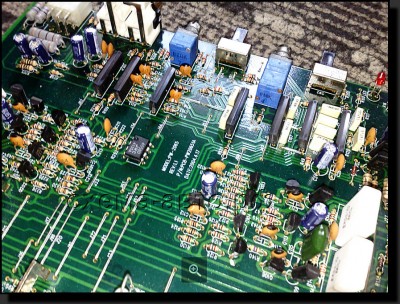
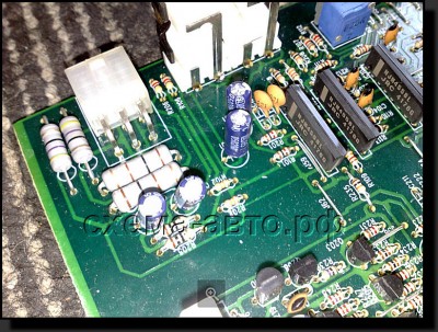
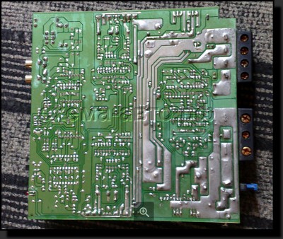
In detail: DIY repair of car audio amplifiers from a real master for the site my.housecope.com.
Car amplifier repair - repair of an auto amplifier for a person familiar with electronic devices is not something difficult and impossible. In this article, I want to share my experience in restoring the performance of failed UMZCH. It is clear that it is simply not realistic to highlight all the moments that arise during practical repairs in this short selection. But nevertheless, if you adhere to certain actions, then in almost 100% of cases it turns out to repair this or that device in a short time. The basic principle when repairing an amplifier is to accurately determine in the circuit the element that has stopped working and thereby disabled the entire system.
After all, as they say in narrow circles of radio mechanics - "There are only two types of malfunction in electronics":
1. The presence of contact where it should not be.
2. Lack of contact where it should be.
1. Screwdrivers of various designs, side cutters, pliers, an assembly knife, tweezers, a magnifying glass - that is, what is needed at least for repairs.
2. Measuring device - multimeters.
3. Regulated bipolar power supply 16 ... 24 or 36v, preferably with output current limiting function.
4. And last but not least, experience in electronics repair.
Determination of a malfunction should begin with checking the output voltage - whether it is there or not. In its absence, the fuse may simply have blown out, there is no reliable contact at the wire terminal, and so on. The moment is standard and ordinary, but it is at this stage that the repair is completed in 10% of cases.
| Video (click to play). |
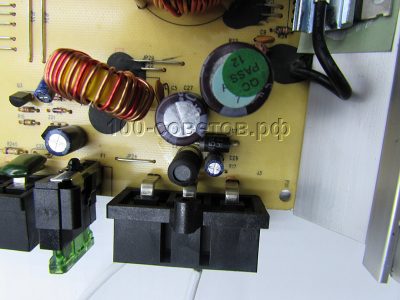
Further action when you start car amplifier repair should be as follows: - search for a schematic diagram for an amplifier, if it was not possible to find it, then here you will have to rely on your experience and knowledge. We remove the cover of the device and begin a visual inspection of the printed circuit board to detect leaks or swelling of electrolytic capacitors, blackening of resistors, breakage of printed tracks, etc. Sometimes only such an examination makes it possible to quickly determine the part that has come out of the standing. Then, with the amplifier turned on, you need to check all the components installed on the board with a touch of your finger. In the case of the release of strong heat on the element, then it can be assumed that the problem may be in it.
Car amplifier repair - this is a search for a malfunction not only in the sound amplification path, but also in the main unit of the amplifier - the power source. We investigate the power supply, output voltage. Basically, car ULFs have bipolar from 20v and more. In case of detection of blackened resistors, punctured transistors, we replace them with serviceable ones.
We turn on the amplifier, after applying voltage, you need to short-circuit the Remout input to the "+" power supply (or to "-" in different ways everywhere) and observe the Protect protection indicator, if the LED is on, therefore, the amplifier has switched to protection mode. This can happen as a result of a malfunction of the voltage conversion module, or a transistor junction in one of the arms is broken. Also, the cause of the breakdown may be the lack of power on the microcircuit installed in the transistor circuit of the converter (usually TL494 or others are installed there).
In addition, for a car power amplifier, protection can also be triggered if one or several UMZCH transistors of one of the channels are knocked out. When the transistor of the output stage of the PA knocks out, a short circuit occurs, a colossal load is created in the PN circuit. As a result, protection is instantly triggered.
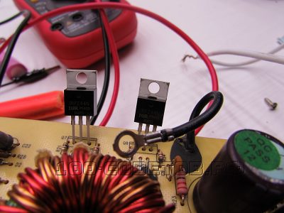
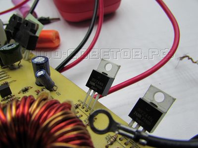
Therefore, continuing car amplifier repair, and after turning on the power of the amplifier, the fuse remains intact, then you need to check the output voltage on the converter, which should be 2 to 20v or more (bipolar). Most likely, when the protection indicator is on, there will be no voltage in the PN output circuit. Based on this, it is necessary to disconnect the PA from the converter. One of the most convenient options would be to tap the transistor leads one at a time on each channel, or disconnect all. After the terminals of the MOSFET transistors have been soldered and the amplifier turns on normally, the protection LED does not light up. Then we find the broken field controller by ringing the transitions and change it.
If, when the voltage is applied, the LED continues to glow, then we continue to look for a malfunction in the converter. First of all, we determine whether there is a voltage on the PN microcircuit, transistors in the path for supplying voltage to the microcircuit can burn out. Pay special attention to the transformer, see if there are any singed turns of enamel wire or breakage. Also, it will not be superfluous to smell if there is a burning smell. In some models of car amplifiers, diode assemblies are installed in the converter circuit between the amplifier, which can also cause the protection to operate.
UMZCH repair is almost the most frequent of the questions asked on amateur radio forums. And besides, it is one of the most difficult. Of course, there are “favorite” faults, but in principle, any of several tens, or even hundreds of components that make up the amplifier can fail. Moreover, there are a great many UMZCH schemes.
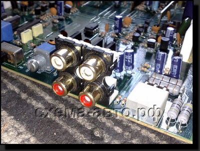
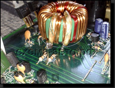
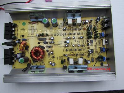
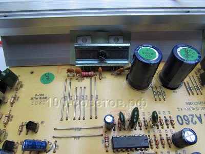
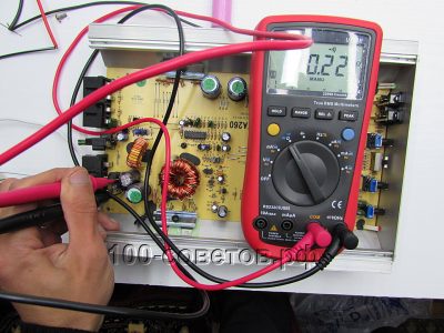
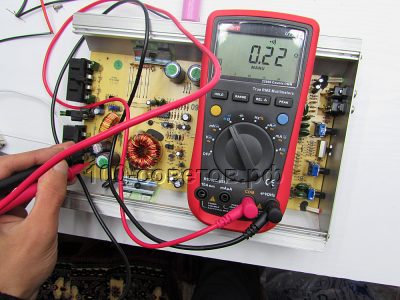
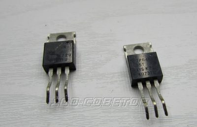
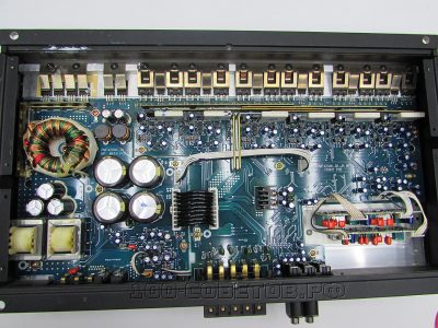
Of course, it is not possible to cover all the cases encountered in the repair practice, however, if you follow a certain algorithm, then in the overwhelming majority of cases it is possible to restore the device's operability in a completely acceptable time. This algorithm was developed by me from the experience of repairing about fifty different UMZCH, from the simplest, for a few watts or tens of watts, to concert "monsters" of 1 ... 2 kW per channel, most of which were sent for repairs without schematic diagrams. The main task of repairing any UMZCH is to localize the failed element, which entailed the inoperability of both the entire circuit and the failure of other stages. Since there are only 2 types of defects in electrical engineering: then the "super task" of the repair is to find the broken or broken element. And for this - to find the cascade where it is located. Further - "a matter of technology." As the doctors say: "The correct diagnosis is half of the treatment." The list of equipment and tools required (or at least highly desirable) during the repair: Consider this algorithm using the example of repairing a hypothetical transistor UMZCH with bipolar transistors in the output stages (Fig. 1), which is not too primitive, but also not very complicated. This scheme is the most common "classic of the genre". Functionally, it consists of the following blocks and nodes: We turn on the amplifier. The lamp should blink (while the filter capacitors are charging) and go out (a weak glow of the filament is allowed). This means that K.Z. on the primary winding of the network transformer there is no obvious short circuit. in its secondary windings. With a tester in the alternating voltage mode, we measure the voltage on the primary winding of the transformer and on the lamp. Their sum must be equal to the network. We measure the voltages on the secondary windings. They should be proportional to what is actually measured on the primary winding (relative to the nominal). You can turn off the lamp, put the fuse in place and turn on the amplifier directly to the network. We repeat the voltage check on the primary and secondary windings. The ratio (proportion) between them should be the same as when measured with a lamp. The lamp burns constantly at full incandescence, which means we have a short circuit. in the primary circuit: check the integrity of the insulation of the wires coming from the mains connector, power switch, fuse holder. We unsolder one of the reasons going to the primary winding of the transformer. The lamp went out - most likely the primary winding (or turn-to-turn circuit) is out of order. The lamp burns constantly in incomplete incandescence - most likely, a defect in the secondary windings or in the circuits connected to them. We unsolder one wire from the secondary windings to the rectifier (m). Do not confuse, Kulibin! So that later it would not be excruciatingly painful from improper soldering back (mark, for example, with pieces of adhesive masking tape). The lamp went out - it means that everything is in order with the transformer. It is lit - again we sigh heavily and either look for a replacement for it, or rewind. 6. It was determined that the transformer is in order, and the defect is in the rectifiers or filter capacitors. We call the diodes (it is advisable to unsolder under one wire going to their terminals, or to solder it out, if it is an integral bridge) with a tester in ohmmeter mode at the minimum limit. Digital testers often lie in this mode, so it is advisable to use a dial gauge. Personally, I have been using the “squeaker” dial tone for a long time (Fig. 2, 3). Diodes (bridge) are broken or broken - we change. Integers - call the filter capacitors. Before measuring, they must be discharged (.) Through a 2-watt resistor with a resistance of about 100 ohms. Otherwise, you could burn the tester. If the capacitor is intact, when closed, the arrow first deviates to the maximum, and then rather slowly (as the capacitor is charged) "creeps" to the left. We change the connection of the probes. The arrow first goes off scale to the right (there is a charge on the capacitor from the previous measurement) and then creeps to the left again. If there is a capacitance meter and ESR meter, then it is highly desirable to use one. We replace broken or broken capacitors. A low frequency amplifier (ULF) is a device every music lover knows about its purpose. This component of the audio system improves the overall sound quality of the acoustics. But like any other electronic devices, AU can fail. For more information on how to repair amplifiers of car audio systems with your own hands, learn from this article. Before repairing, installing and adjusting the ULF in your car, you need to understand the breakdown. It is simply impossible to consider all the faults that can be encountered in practice, since there are a lot of them.The main task of repairing a device for sound amplification is considered to be the restoration of a broken component, the breakdown of which led to the inoperability of the entire board. In any electrical engineering, including amplifiers, there can be two types of faults: Automotive ULF microboard Repair of car amplifiers first of all starts with ULF diagnostics: Soldering iron on the amplifier chip Do-it-yourself car amplifier repair is carried out in accordance with what problem was identified during its operation: Now let's move on to the question - how to set up a car amplifier? There are several configuration options - for use with and without a sub. How to properly configure the ULF without a subwoofer - first you need to set the following parameters: After that, adjusting the settings of the audio system with an equalizer, the system is tuned to suit your preferences. The volume must be set to maximum and include some track. How to set up an amplifier in a car for use with a subwoofer is also not particularly difficult. For correct configuration, it is advisable to use the following parameters: It is very important to observe these parameters, since they determine the quality of the adjustment and, accordingly, the sound of the audio system. In general, the setup procedure is similar, using the level control to provide a more harmonious sound. The sensitivity of the rear and front speakers should be matched to each other. If you don’t understand anything about this, it’s better not to go there, because repairs will cost more after you burn or break it. Sorry, there are currently no polls available. In more detail, the recommendations and procedure for repairing the microcircuit are described in the video below (the author is the Soldering TV channel). Sun 6 Jul 2014 It's no secret that to get high-quality sound and powerful bass in a car, you definitely need a power amplifier. Today, fortunately, on the market you can find car amplifiers for every taste, it all depends on your specific needs. An amplifier for 200-400 watts is enough to power the standard car acoustics, but among us there are true connoisseurs of sound pressure, audiophiles and music lovers who will not be surprised by a couple of hundred watts of sound power. It is for such people that class D amplifiers were invented - digital audio amplifiers that have high efficiency, compact dimensions and many other advantages. Unfortunately, a car amplifier sometimes breaks down, in some cases repairs are more expensive than the initial cost of the amplifier itself, so it is very desirable to consider or try to repair it yourself, because sometimes a blown fuse can be the cause of a breakdown. Having at hand a simple and cheap multimeter with a diode continuity mode, you can find most of the defects that are very often observed in many car amplifiers. Any car amplifier consists of three main parts - a voltage converter, a power amplifier block and a filter block (crossover). A voltage converter or inverter is the most vulnerable part in any amplifier - 90% of the problems are associated with this particular node. The converter essentially powers the entire amplifier including the filter bank. Exclusively all voltage converters are made according to a standard push-pull circuit using a PWM controller, most often on a TL494. Then everything is standard - driver, power transistors, transformer, rectifier and filter unit. In some (cheap) amplifiers, inverter circuits of an unregulated type are implemented - in a word, there is no control of the output voltage, of course this is quite bad, but it is not at all a necessary process if the amplifier is not sensitive to the supply voltage and is a cheap model. Converter transistors - they are the ones that fail most often. In cheap Chinese amplifiers, transistors are strangely marked, even if you cannot find similar transistors, you just need to know one thing - the keys can always be replaced with IRFZ40 / IRFZ44 / IRFZ46 / IRFZ48 or more powerful IRF3205, the choice of keys is actually quite large, I just listed the most available options. In general, N-channel high-power field-effect transistors are used exclusively in all inverters of automobile low-frequency transistors - up to the brutal IRF1404. Initially, we check the board by eye - sometimes visible defects can be observed (burned out resistor, broken tracks on the back of the board, etc.) Before replacing the transistors, you must first check the power fuse, the diode on the plus and minus buses (when the power is reversed, it also burns out), and only after you have made sure that everything is ok with these parts, we replace the keys. For a more professional repair, an oscilloscope is indispensable. Initially, you need to check the presence of rectangular pulses at the 9th and 10th output of the generator microcircuit, if any, then the microcircuit is working. Then we check for the presence of the same pulses after the driver - on the gates of the field switches. If there are no pulses, then most likely the problem is in the driver, if they are, then without hesitation we replace the field-effect transistors. It is extremely rare that there is a problem with the power amplifier, the converter burns out first, keeping the amplifiers. In the converter, other breakdowns are possible, although very rarely. There is a problem with the input and output capacitors or the diode rectifier, which rectifies the high frequency AC voltage from the transformer. In connection with the increasing attempts of novice people to hand-to-hand to repair a suddenly silenced auto-amplifier - the present is offered for reading (recommended): Repair actions. The points: 1. The coolest option is “Chef, this is Lelik, the truncated is gone” (c) 1.1 With an unknown pre-history of failure, it makes sense to look at the protective diode (usually of an elephant-like design) for the input power supply and, at the input capacitors of the power filter. If there are no clearly distinguishable problems in these circuits associated with the consequences of incorrect switching on of an external battery, and SUCCESSFUL - attempts to reverse the polarity - go to. 2. Very quickly we call the tester the power keys of the power supply unit (PSU).As a rule, we see a number of parallel cascades. If at least one of them has died - we valiantly remove everything - one hell of a replacement, you need to put ALL radio elements from one batch. From a heap of burnt trash (or from a "stash") - select ONE (.) Set, (ie a pair), and solder it into the appropriate place (on different shoulders, essno). It will be absolutely NOT superfluous. 3. Then check the power amplifiers for fatal damage. You can - ring out the transistors of the output stages with the tester, you can - simply apply a voltage of the order of +/- 25 Volts from the external power supply unit directly to the output capacitors of the standard power supply unit. 3.1. If the situation with the power amplifier raises doubts (or a smoke screen for switching on from an external power supply) - bravely remove the transistors of the output stage (or output stages - ALL.) - and supply B + and REM to the device. We look at the output voltages of the built-in PSU. If they are sharply underestimated - such as +/- 10 Volts - there is a serious suspicion of a defective transformer. It is very useful to view the corresponding pictures with an oscillator and evaluate the frequency of generation of the power supply converter, if it is higher than 0.1 MHz - this is not entirely normal. We can already confidently talk about a not very good transformer that needs to be rewound. 4. Transformer - rewound, and - heroically soldered. We connect the power and check the presence of normal output voltages. It is not harmful to make sure that there is a voltage of +/- 15 (+/- 12) Volts to power the pre-amplification stages, which, as a rule, is formed from the main supply voltage by a pair of linear stabilizers. 5. We connect an external signal (sound generator, for example) and look with an oscilloscope to see if the signal passes through the stages of power amplifiers. As a rule, circuits based on complementary pairs work quite stably even WITHOUT output stages, which makes it possible to quickly find defective radioelements during repairs, dispensing with acoustic and smoke effects. This technique in no way pretends to be exhaustive (for example - as a matter of course - I did not write about a visual check of the condition of printed conductors, radioelements and the quality of installation). This is just part of a typical set of standard repair procedures for most amplifiers today. If these actions are performed, and the result is unsatisfactory, then it is already possible to create a new topic with shouts of “HELP”, not forgetting to inform the interlocutors about all the actions performed with the device. Good luck! Today they brought in such an interesting car amplifier for repair. According to the owner of the car, such an amplifier has been in the car since time immemorial. The amplifier is the most common - a four-channel transistor amplifier with a built-in voltage converter. Everything would seem to be fine, but here the emblem is LADA, was it really collected in Russia? Later, the documentation for the AL-100.4 was found on the Internet. Rated power, 4 Ohm 50 W x 4 Indeed, quite a powerful and good amplifier, judging by the board. A huge transformer immediately catches the eye - it is he who powers the entire installation - 4 amplifiers with a power of 100 watts each. Muscles are powerful field keys (they are the ones that burned out in this amplifier, but more on that next time). The power choke is wound on a ring from iron powder. Consists of 7 turns, wound immediately with 5 cores of 0.8mm wire. Powerful diode from power reversal. The generator is built on the traditional TL494 microcircuit with additional drivers to amplify the microcircuit signal. It is interesting that 2 drivers are used here (4 pairs of low-power transistors). Further, there are already powerful field switches of the 50N06 series.This is a fairly powerful series of field-effect transistors, there are 4 of them in the circuit, two transistors per arm. The power of the converter is more than 400 watts, this is by eye. The transformer itself is powerful enough, which has two secondary windings. The voltage is rectified using powerful (Schottky diodes (diode assemblies). Further smoothing capacitors of 2200 uF 35 Volts per arm. Each of the secondary windings feeds two amplifiers. In appearance, the AL-100.4 amplifier honestly gives its 4x100 watts, since both the power of the amplifiers and the voltage converter allow this. Next, we will consider the cause of the malfunction and repair of such an amplifier and a few more interesting facts. We continue the topic about the LADA AL 100.4 car amplifier. The converter with power amplifiers are mounted on one board. LPF summator and timbre block on a separate one. On the board we can see 4 completely identical power amplifiers. Each amplifier develops a maximum power of about 100 watts. The output stages are based on powerful bipolar transistors NPN-2SD718 (8A, 120V, 80W) and PNP-2SB688 (8A, 120V, 80W). This is a fairly well-known complementary pair that has found wide application in high-quality transistor amplifiers. Each of the amplifiers has one output stage and is powered by +/- 30 Volts bipolar voltage, so 100 watts for each amplifier is not a problem. The amplifiers can also be bridged, thus increasing the output power to 200 watts per channel. But in this case, the amplifier will operate in stereo. The reason for the malfunction of such an amplifier was in the voltage converter. In general, in almost all automobile amplifiers of increased power (with the use of PN) such a problem occurs. Of course, the amplifier is protected by a fuse, there are two of them, but the device, protected by a fuse, burns out first, having protected the fuse - this is not a philosophical expression, but pure truth. According to the owner, the amplifier failed after he accidentally reversed the polarity of the power connection. Strange as it may seem, neither the fuse, nor the built-in protection, and even the protective diode from overplacing saved the amplifier. Power keys flew out at once, and there are as many as 4 of them in the circuit. Here are used quite powerful field drivers of the 50N06 series, in fact, they are almost complete analogues of the IRFZ44, so that you can replace it, but after checking the circuit in advance. It is quite simple to check the circuit for operability. You need to connect the power and check the generation of rectangular pulses at the 9th and 10th pin of the microcircuit. If there is generation, then you can safely replace them. In my case, IRFZ44 transistors were used. The amplifier is working as good as new! This completes the ULF repair. Keep in mind, before turning on any electronic device in the car (car radio or power amplifier), pay strict attention to the polarity of the connection, do not hope that the protections can be saved, practice shows that during real threats, none of them work , then you will have to pay a lot of money to repair expensive equipment. Recently, a friend asked to repair a car amplifier that had been lying in a repair shop for about a month, and as a result, the master asked for an exorbitant price of 2,500 rubles. Blaupunkt GTA-260 amplifier with a declared power of 400 watts. Actually a good two-channel amplifier, though at the expense of power .... lies. A symptom of a malfunction is a short circuit between the positive and the power supply ground, the fuse is intact. After opening, the first thing I did was check the diode, it is natural to ring in both directions, but there is no need to solder it yet. In 90% of cases of such problems, the power N-channel field switches are to blame, which are in the input circuit and are designed to swing the power transformer, in this sample there were switches of the IXTP64N055T type, for 64 Amperes 55 Volts. And the problem turned out to be in them, both burned out.As a rule, in budget amplifiers of such a plan, where there is only one pair of keys in the inverter, I put the IRF3205, but only irfz44 was at hand, and I put them. Naturally, their maximum current is slightly less, but the difference in power will be imperceptible by ear, taking into account that the amplifier worked with broadband acoustics, and not with a subwoofer. I didn't even understand why the master asked for such an amount for repairs and was looking for a problem for about a month, a problem that can be identified without even opening the amplifier ... In general, this amplifier is built according to the standard topology - a push-pull inverter, based on the TL494 PWM controller, a node for high-speed discharge of the gate capacitance of field workers based on two low-power complementary pairs, field switches, a transformer, an output rectifier with a filtering unit and a power amplifier. There are two channels here, they work in class AB, the power, purely from practice, I will say that no more than 100-120 watts per channel. There is also a signal filtering unit for the operation of an amplifier with a subwoofer and pre-amplifiers, all this part is implemented on budget dual op-amps BA4558. Pleases the presence of a choke at the 12 Volt power input. The board looks like a lot of jumper wires for me, the components are crooked, if you pay attention, you can see some solder balls, I never liked blaupunkts. If anyone wants advice on choosing an auto amplifier, I advise you to look towards alpine, I have repaired and studied many amplifiers - only alpine can boast of real sound quality as well as the assembly and wiring of the board, and at the end, for comparison, my alpine mrv-f450 board. I understand that from a price point of view, it's like heaven and earth, but it's better to take a good one right away - I assure you that alpine has never been repaired, I don't remember what year without any complaints. Hmm ... about working in class AB, you went too far. Even your Alpine is not able to hold even 1 watt in class A. And the master spoke correctly, the brazen people went, they want to do everything for free! Sometimes, even from over 100r, a scandal is resisting! Of course, it is not possible to cover all the cases encountered in the repair practice, however, if you follow a certain algorithm, then in the overwhelming majority of cases it is possible to restore the device's operability in a completely acceptable time. The main task of repairing any UMZCH is to localize the failed element, which entailed the inoperability of both the entire circuit and the failure of other stages. Since there are only 2 types of defects in electrical engineering: 1) The presence of contact where it should not be. 1) Screwdrivers, side cutters, pliers, scalpel (knife), tweezers, magnifying glass - i.e., the minimum required set of conventional assembly tools. The first point of any repair is an external examination of the subject and sniffing it (!). This alone sometimes allows us to at least assume the essence of the defect. If it smells like burnt, it means that something is clearly burning. Checking the presence of voltage at the input: the fuse is stupidly blown, the wires are loose, etc. The stage is the most commonplace in its essence, but at which the repair is completed in about 10% of cases. We are looking for a circuit for an amplifier. In the instructions, on the Internet, from acquaintances, friends, etc. Unfortunately, more and more often in recent years - unsuccessfully. Didn't find it - we sigh heavily, sprinkle ashes on our head and start drawing a diagram on the board. You can skip this stage. We open the subject and make an external examination of its "giblets". Use a magnifying glass if needed. You can see the destroyed cases of semiconductor devices, darkened, charred or destroyed resistors, swollen electrolytic capacitors or electrolyte drips from them, broken conductors, printed circuit board tracks, etc. If one is found, this is not yet a reason for joy: the destroyed parts may be the result of the failure of some "flea", which is visually intact. We check the power supply, the output voltage, as a rule, in automobile ULF power supply is two-polar, starting from 2x20 volts and above.If you find burned out parts (resistors, transistors), then we change them. We supply power to the amplifier and close the Remout input to the plus of the power (or to minus, where else), and look at the PROTECTION protection LED, if the LED is on, then the amplifier has gone into protection.Maybe this is for several reasons: Something is wrong in the converter voltage, the transistors of one of the arms may be knocked out, or there may be no power on the microcircuit that shakes the transistors of the converter (as a rule, it is TL494 or SG3xxx, there may be others). In addition, the amplifier can go into protection for the reason that one or more transistors of the power amplifier could fail, no matter which channel. When the PA transistor fails, as a rule, it shorts, due to the high load, the PN goes into protection. Therefore, if after the power supply to the PA the fuse does not burn out, we check the voltage at the output during the PN, as already mentioned, it should be about 2x20V and higher (two-wire). Most likely, when the PROTECTION LED is on, there will be no voltage at the PN output, therefore it is recommended to disconnect the amplifiers from the converter. The easiest option is to unsolder one transistor from each channel (you can do everything). If, after unsoldering the field workers, the amplifier turns on and the PROTECTION does not light up, we change the dead short-circuited transistor to a serviceable one. If the LED does not go out, then we are digging the voltage converter, we check whether the voltage is supplied to the PN microcircuit, there may be transistors along the power circuit of the microcircuit through which power is supplied. Also pay attention to the transformer of the converter, whether there are burnt coils, breaks, snot. And do not be lazy, smell if it smells burnt. It happens that in car amplifiers, diode assemblies are installed in series between the PN and the amplifier, due to their malfunction, the amplifier can also go into protection, usually this happens when the volume of the amplifier is more than average - in this case, either the protection LED blinks or the amplifier immediately goes into protection. This article is intended for non-professional radio amateurs, for those who do not know how to hold a soldering iron in their hands but for one reason or another lack the skills or knowledge base to repair such equipment. If you have questions about amplifier repair or need help with repair, a topic on the forum, they will try to help you!
Is your TV, radio, mobile phone or kettle broken? And you want to create a new topic about this in this forum? First of all, think about this: imagine that your father / son / brother has an appendicitis pain and you know from the symptoms that it is just appendicitis, but there is no experience of cutting it out, as well as the tool. And you turn on your computer, access the Internet on a medical site with the question: "Help to cut out appendicitis." Do you understand the absurdity of the whole situation? Even if they answer you, it is worth considering factors such as the patient's diabetes, allergies to anesthesia and other medical nuances. I think no one does this in real life and will risk trusting the life of their loved ones with advice from the Internet. The same is in the repair of radio equipment, although of course these are all the material benefits of modern civilization and in case of unsuccessful repairs, you can always buy a new LCD TV, cell phone, iPAD or computer. And for the repair of such equipment, at least it is necessary to have the appropriate measuring (oscilloscope, multimeter, generator, etc.) and soldering equipment (hairdryer, SMD-hot tweezers, etc.), a schematic diagram, not to mention the necessary knowledge and repair experience. Let's consider a situation if you are a beginner / advanced radio amateur soldering all sorts of electronic gizmos and having some of the necessary tools. You create an appropriate thread on the repair forum with a short description of “patient symptoms”, ie. for example “Samsung LE40R81B TV does not turn on”.So what? Yes, there can be a lot of reasons for not switching on - from malfunctions in the power system, problems with the processor or flashing firmware in the EEPROM memory. The purpose of this post is not any PR of repair shops, but I want to convey to you that sometimes self-repair can be more expensive than taking it to a professional workshop. Although, of course, this is your money and what is better or more risky is up to you. If you nevertheless decide that you are able to independently repair the radio equipment, then when creating a post, be sure to indicate the full name of the device, modification, year of manufacture, country of origin and other detailed information. If there is a diagram, then attach it to the post or give a link to the source. Write down how long the symptoms have been manifesting, whether there were surges in the supply voltage network, whether there was a repair before that, what was done, what was checked, voltage measurements, oscillograms, etc. From a photo of a motherboard, as a rule, there is little sense, from a photo of a motherboard taken on a mobile phone there is no sense at all. Telepaths live in other forums. The format of your post should be as follows: Topics with the title “Help fix the Sony TV” with the content “broken” and a couple of blurred photos of the unscrewed back cover, taken with the 7th iPhone, at night, with a resolution of 8000x6000 pixels are immediately deleted. The more information you post about the breakdown, the more chances you will get a competent answer. Understand that the forum is a system of gratuitous mutual assistance in solving problems and if you are dismissive of writing your post and do not follow the above tips, then the answers to it will be appropriate, if anyone wants to answer at all. Also note that no one should answer instantly or within a day, say, no need to write after 2 hours “That no one can help”, etc. In this case, the topic will be deleted immediately. If you decide to take your broken equipment to the nearest workshop, but do not know where, then perhaps our online cartographic service will help you: workshops on the map (on the left, press all buttons except “Workshops”). You can leave and view user reviews for workshops. For repairmen and workshops: you can add your services to the map. Find your object on the map from the satellite and click on it with the left mouse button. In the field “Object type:” do not forget to change to “Equipment repair”. Adding is absolutely free! All objects are checked and moderated. A discussion of the service is here.
When the power is connected - a fuse (of any reasonable wattage) - lights up to thunderous applause. Next steps:
Maximum power, 4 ohms 100 W x 4
Rated power in bridged connection, 4 Ohm 100 W x 2
Maximum power in bridged connection, 4 Ohm 200 W x 2
Recommended fuse rating 20 A x 2
Dimensions 290 x 57 x 243 mm
Signal to noise ratio> 80 dB

2) Lack of contact where it should be.The list of equipment and tools required (or at least highly desirable) during the repair:
2) Tester (multimeter).
3) Bipolar regulated power supply 15 ... 25 (35) V with limited output current (highly desirable).
4) And, finally, the most important tool is the head on the shoulders (required!).
More advanced users can find the blackened element on the board and attach a photo to the post. However, keep in mind that you are replacing this radio element with the same one - it is not yet a fact that your equipment will work. As a rule, something caused the combustion of this element and it could “pull” a couple of other elements along with it, not to mention the fact that it is quite difficult for a non-professional to find a burned-out m / s. Plus, in modern equipment, SMD radio elements are almost universally used, soldering which with an ESPN-40 soldering iron or a Chinese 60-Watt soldering iron you risk overheating the board, peeling tracks, etc. The subsequent restoration of which will be very, very problematic.
Before creating a post, be sure to use the search on the forum and on the Internet. Read the relevant topics in the subsections, perhaps your problem is typical and has already been discussed. Be sure to read the article Repair strategy
You should make every effort to find a breakdown on your own before you get stumped and decide to go to the forum. If you outline the entire process of finding a breakdown in your topic, then the chance of getting help from a highly qualified specialist will be very great.
![]()
Video (click to play).

