
In detail: do-it-yourself repair of a wireless echo sounder sensor from a real master for the site my.housecope.com.
Do-it-yourself repair of the Matrix 37 echo sounder sensor
Do-it-yourself repair of the Matrix 37 echo sounder sensor
I had a sensor failure while fishing: after a two-kilometer transition to a catching spot in planing mode, the echo sounder complained that it had lost contact with the sensor. Since there were no shocks on the transducer during the transition, a failure could arise either due to a software failure of the echo sounder (this happens from time to time with Humminbirds), or due to a cable break. Rebooting the echo sounder did not help. A quick inspection showed that some of the cable wires were broken at the place where the cable was terminated in the sensor. Since paying a third of the cost of the echo sounder for a new transducer, which, moreover, was promised to be delivered to order (this is at the very height of the season!) Seemed too "bold" to me, I decided to repair it myself. It took one evening to renovate. The Americans did not come up with anything new - piezoceramic plates with silver-plated surfaces are used as emitting and receiving elements of the sensor, to which the echo sounder wires are soldered.
For repair, you need to disassemble the sensor, re-solder the wires to the plates and assemble the sensor.
The M37 sensor consists of two plastic halves, which contain three piezoceramic plates and a temperature sensor. The inner volume of the sensor is filled with a black elastic rubber-like mass resembling hardened sealant. Care must be taken when disassembling the sensor, since the silver sprayed (deposited?) On the plates can be easily torn off together with the sealant. In addition, mindlessly wielding a knife and a screwdriver, you can split the plates themselves in no time.
| Video (click to play). |
The plastic halves of the sensor are connected (glued) on only one sealant. There are no other connecting elements. To separate the upper and lower halves, use a sharp knife to cut the sensor joint to a depth of 3-5 mm. The temperature sensor, fixed in the "stern" of the sensor, looks like a metal "fungus" and has very thin leads, breaking them off flush, you will lose the ability to determine the temperature.
Slightly widening the joint, remove the upper plastic cover of the sensor. It is not so easy, but quite doable, the main thing is not to rush. The top and bottom halves of the transducer have thin rails molded in one piece with the halves of the transducer. They are needed for the correct installation of the plates, so it is advisable not to break them, at least in the "stern" part, especially in the lower half.
After the upper half of the sensor has been removed, do not rush to remove the plates. Using a scalpel and small nippers, carefully remove as much of the sealant as possible. The wires leading to the temperature sensor should be bite off 5 mm from its body in advance - this will help not to break off the leads. The wires leading to the plates should also be bitten off in advance - this way it is easier to avoid the separation of the silvered layer from the plates. Do not forget about the common wire connecting all the plates from below. When most of the plate is freed from the sealant, carefully, trying not to break either the plates themselves or their guides, pry off with a screwdriver (knife) and remove the plates from the bottom.
Before filling with sealant, the plates are covered with something like expanded polyethylene (polyurethane?). It must be removed by simply rolling it with your fingers, like the remnants of rubber glue.
Clean both halves of the sensor from sealant residues. Insert the cable through the hole provided in the upper half.
Solder the cable wires to the plates and the temperature sensor. Solder the braid of the cable from below to all plates and one of the terminals of the temperature sensor.Piezoceramic plates are sensitive to overheating, so it is advisable to use a VOODU alloy and a low-temperature soldering iron.
Fill the bottom half of the sensor with sealant. Install the plates and temperature sensor with soldered wires in the bottom half. Pay special attention to the installation of the side beam plates - they must be installed SYMMETRICALLY relative to the vertical, otherwise, at the same depth, the readings from the right and left beams will be different.
Fill the plates with sealant on top. Install the upper half of the sensor. Wrap the sensor with electrical tape and leave until the sealant cures.
P.S. Just in case, here is the wiring of the sensor cable connector. The sensor connector is easy enough to disassemble by cutting it from both sides along with a sharp knife. When assembling, fill the inside with the same sealant that was used when repairing the sensor.
An article from the site “Bearded page“
Message kolosov » 21.11.2013 09:15:38
Friends, if you have any problems while using your fishfinder, let's solve them together.
About myself:
Electronic engineer. I have been confidently holding a soldering iron since 1980.
I work in a service center. Repair of cash registers, computer cash systems and household appliances.
This is not an ad.
Repairing echo sounders is my hobby.
Write about your problems in this thread.
Call in person. +375 (29) 7145728 MTS.
Vitebsk.
I will try to help you to the best of my ability.
P.S. When asking questions on the forum, please be sure to indicate where you are from.
Message kolosov » 27.10.2014 19:10:10
Message kmoln » 27.10.2014 19:16:28
Message kmoln » 27.10.2014 20:07:30
Message xanti » 06.11.2014 15:38:05
And no one has come across such an incorrect operation of the echo sounder:
It shows everything perfectly, well, let's say the depth is 4.2 meters, the fish sometimes squeaks into the floor of the water. Suddenly, the depth readings doubled - 8.5 meters and at the depth of the real bottom (i.e. already at the bottom of the water on the screen) begins to show fish in schools, on the screen there is a black strip of fish of different sizes. And such "drops" of readings are unpredictable and do not depend on depth and other factors. Moreover, you can get real readings for an hour, or you can see such a jamb in an hour 10 times. It is treated by repeated on / off of the device.
Echo sounder FishFinder Lucku FF718li, wired transducer. Thought the problem was in the cable / connector. The cable (it was 7m) was shortened to 4m and rang, the “daddy” connector was soldered (it was made for 90 ″, very unsuccessfully). As a result, it became 3 times less likely to fail, but it was not cured. What do you recommend?
Actually, all the critical points on the board itself disappeared along the way, but this only led to the fact that the echo sounder stopped seeing the wireless sensor-boat. because the arms grow out of w .. But that's a completely different story. kolosov Advise something.
PS Yes, it also turned out that the cable to the sensor consists of “3 cores insulated + 1 bare ground” and is shielded only with a very thin foil, which is not connected to the earth wire in the sensor and in the connector, but only touches it along the entire length of the cable. Maybe the dog is buried here? I actually do not know how the quality of the cable to the sensor affects the readings. I just know that the device is configured for some value of the capacitance (hundreds or several thousand picofarads) of the sensor + cable, which can actually affect the readings.
Message kolosov » 06.11.2014 18:48:32
Message xanti » 06.11.2014 20:18:51
12 cm below the keel - no effect. Apparently the hardware or raw firmware was problematic. By the way, the device is not Russified, although in the internet they write what is with the Russian firmware. sedes.html. In general, I think that this is not yet a run-in damp model, there is no information on it.
Message sansanich » 28.11.2014 23:21:33
Message kolosov » 29.11.2014 22:05:04
Sansanych, good evening.
I have several questions at once:
How many years has the echo sounder been in use?
Has the sensor been dropped (or hit)?
During storage, was the door kept open and the CR-2032 battery removed?
Did water get into the sensor?
Is there an icon on the display 
I suspect that first you have to replace the CR-2032 battery in the sensor. If there are traces of corrosion in the battery compartment, remove with alcohol.
Here are the Russian instructions for your fishfinder:. eholot.pdf
Message sansanich » 29.11.2014 23:43:34
Message kolosov » 30.11.2014 16:07:30
Message sansanich » 30.11.2014 18:31:16
Message Boatswain » 01.12.2014 12:25:58
Good afternoon.
I am sorry to bother you.
If possible - help me with one question.
The question is as follows:
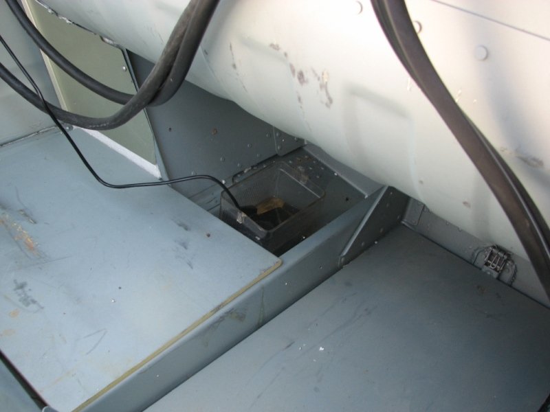
On one of the tugs we are designing, a 520-5MSD Echo sounder sensor was installed.
During the sea trials of this tug, the following was revealed:
1. At speeds up to 7 knots - the sensor works perfectly.
2. Unfortunately, at a speed of 7 knots to 12, the sensor was not monitored.
3. At a speed of 12 - 12.2 knots - it was revealed that on the echo sounder screen - the depth jumps from 0 to XXX depth.
That is, the echo sounder does not work stably.
4. Sea trials were not carried out in calm weather - the only thing I know is that at that moment there were grains of soil in the water.
What could be the reason for this phenomenon?
The attachment is where the echo sounder is installed. The echo sounder is installed on the Starboard side, 750mm from the DP.
If it's not difficult to consult us with our problem or tell me who can help.
Thanks in advance.
Message kolosov » 01.12.2014 14:32:31
The boatswain wrote: At a speed of 12 - 12.2 knots - it was revealed that on the echo sounder screen - the depth jumps from 0 to XXX depth.
That is, the echo sounder does not work stably.
4. Sea trials were not carried out in calm weather - the only thing I know is that at that moment there were grains of soil in the water.
What could be the reason for this phenomenon?
The attachment is where the echo sounder is installed. The echo sounder is installed on the Starboard side, 750mm from the DP.
If it's not difficult to consult us with our problem or tell me who can help.
Boatswain, good day.
You have a cool fishing boat 
.What to say about your problem. Any sensor sooner or later (with increasing speed) begins to lose its bottom. This is due to many reasons. Including with the properties of water itself (the presence of suspended matter and turbidity).
But more often the reason is the appearance of small air (vapor) bubbles in the water under the sensor under certain modes of fluid flow. The so-called cavitation.
It is impossible to completely eliminate this phenomenon. Changing the location of the sensor may help in part. The sensor should not immediately be fixed thoroughly (on epoxy resin), but fixed, for example, on a thin layer of plasticine (the presence of air bubbles between the sensor, plasticine and the bottom is not allowed. After finding the optimal installation point for the sensor, it must be fixed thoroughly (naturally, again pay attention to bubbles air).
And further. The outside of the bottom of your boat is most likely treated with a special corrosion protection agent. Probably more than once. Probably over corrosion. Bottom fouling is also possible. All this increases the thickness of the material that must penetrate the echo sounder beam and does not at all contribute to improving the transmission of the reflected signal (it is much weaker than the emitted one).
I just looked. And your sensor is installed through a hole in the bottom of the boat:
Perhaps it was fastened incorrectly? Or is the sensor overgrown? Well, the installation location may have been chosen incorrectly.
These ridiculous malfunctions appeared repeatedly on my echo sounder and my friend's echo sounder (both ER-4Pro).
It's good when there is a service. It's bad when he's far away. (folk wisdom 
)
We live in Belarus. There is no metro to Zelenograd. 
I repaired the sensor on my friend's echo sounder about 2 years ago. Then I went not quite the right way (I began to disassemble it from the side of the radiating plate of the piezoelectric plate). Disassembled neatly. It was this disassembly that made it possible to clearly imagine how the sensor was assembled and how it is easier to repair it (no matter how bitter it sounds
). The sensor has been restored and is still working.
For sensors Practice 2 typical
malfunctions: 1. When screwing in the head, the echo sounder does not turn on or turns on and then turns off.
2. Periodic disappearance or weakening of the signal when changing the torque of the sensor.
The first malfunction is due to the fact that the conical spring pressing the negative contact of the battery must have ideal electrical contact with the metal housing of the sensor. It is when the sensor is screwed into the barrocasing by the thread
power is fed further along the cable to the “head” of the echo sounder. There shouldn't be any losses here. And they are.Moreover, up to the complete absence of contact of the spring with the brass body of the sensor. In the best case - the mechanical contact of the half-turn of the oxidized spring with the thread edge of the body
 . Inside the sensor, the spring is not connected to the brass body .
In the second malfunction (loss of the chuyka), the ears grow from the same place.
The antennae on both sides of the sensor transmit a signal to / from one of the plates of the piezoceramic plate (the second plate is connected to the sensor body). To this piece of steel wire (well, it does not look like beryllium bronze 
), coming out in the form of tendrils, inside the "soldered" wire coming from the plate of the piezoelectric sensor. “Soldered” in quotes - because nothing can be soldered to this piece of wire. The manufacturer's soldering has only the appearance of the contact. Oxidized wire sooner or later rejects the solder and. glitches begin with the determination of depth and underwater objects.
How are we going to treat?
We bite off the spring.
Remove the sticker with the “-“ sign. Under it is a layer of translucent plastic from a heat gun. We delete it.
Below is a layer of foam rubber (vibration damper). Carefully pick it out. A wire curved by our tight twists appears, creating antennae along the edges of the sensor. On it we see a drop of solder, which, with light effort, moves along the wire and then falls off altogether. Together with this, the contact of the wire coming from the piezo crystal completely disappears. This is the delayed-action mine laid by the manufacturer. 
.
Carefully remove the rubber filler further (but don't throw away the crumb!). We are looking for the "tail" of the wire. If we “lose” it, we will have to pick it up to the lining of the piezoelectric element and solder it directly to it - and this is an extra gimor. We don't need this.
We extend the wire from the piezoelectric crystal and solder it to the transverse contact wire. Before that, we thoroughly clean this wire in the “well” of the sensor body (and who said that it would be easy?
). Tin this piece of wire as well as the tapered contact spring without good flux impossible... I used F38N flux followed by alcohol rinsing.
Half the battle is done! 
Now we will assemble the sensor.
Crumbs of rubber left over from picking the "bowels" of the sensor, we fill its insides, burying our hopes for the restoration of the sensor under this crumb
 .
. Then we apply a layer of silicone auto-sealant on top (I used Mannol). Apply sealant instead of crumbs it is forbidden! Firstly, it does not sufficiently damp the signal (unlike foam rubber), and secondly, these sealants are still that infection. They contain acetic acid, which can have a negative effect on the solder and piezoelectric crystal plates. Therefore, only crumbs on top.
But don't be afraid to use silicone sealant. The acetic acid contained in it evaporates quickly after polymerization of the sealant (a day is enough for a thin layer).
In the meantime, we will secure the spring. And we will not just fix it, but create an excellent electrical contact between it and the brass body of the sensor. We will solder it. First, we will clean the half-coil and tin it (greetings from the F38N flux and technical alcohol). We will tin the inner groove of the threaded part of the brass sensor, insert the spring there and solder it for half a turn (I additionally lowered the small tail of the spring down to the sealant).
After a day of drying the sealant, carefully fill the remaining cavity with epoxy resin and apply a “-“ sticker on top.
Once the resin has cured, you can put the transducer back in place and check the operation of the echo sounder.
The sensor won't let you down anymore.
Everything written above IMHO. If you follow my instructions, you will do it at your own peril and risk.
The transducer is the "antenna" of the echo sounder. He transforms 
electrical energy from the transmitter into a high frequency sound wave. The sound wave from the transducer travels through the water and back, bouncing off any object in the water.When the reflected signal hits back into the transducer, the Sonar Transducer converts the sound into electrical energy, which is sent to the echo sounder receiver. The frequency of the transducer must match the frequency of the sonic receiver of the echo sounder. In other words, you cannot use an 83 kHz converter on a 200 kHz audio receiver. The transducer must be capable of transmitting powerful pulses from the transmitter, the Humminbird sensor, converting electrical pulses into sound pulses with minimal power loss. At the same time, it must be sensitive enough to receive the weakest echoes. All this refers to a certain set frequency and the converter must ignore the echoes arriving at other frequencies. In other words, the converter must be very efficient.
The active element of the converter is an artificial crystal (lead zirconate or barium titanate), components 
mixed and then molded. This mold is placed in an oven where it is transformed from a mixture of chemicals into a solid crystal. Once the crystal has cooled down, wires are attached to both sides of the crystal. The wires are firmly soldered to the surface of the crystal so that the crystal can be connected to the converter cable. The shape of the crystal determines the frequency of its operation and the conical angle. For round crystals, used by most echo sounders, the thickness determines its frequency, and the diameter determines the cone angle, or the angle of the field of view. For example, in a 192 kHz echo sounder, with a 20 degree tapered angle, the crystal is approximately one inch in diameter, while an eight degree echo sounder requires a crystal that is several inches in diameter. Bottom line: a larger crystal diameter - a smaller conical angle. This is the reason why a 20 degree tapered transducer is much smaller than an 8 degree tapered transducer when using the same frequency.
The transducers are produced in various shapes and sizes. Most transducers are made of plastic, but some thru-body transducers are made of bronze. As shown in the previous section, the frequency and taper angle determine the size of the crystal. Therefore, the placement of the transducer is determined by the size of the crystal inside. There are four main placement styles in use today. Thru-Body, Portable, Transom Mount and Wireless.
Thru-hull transducers are epoxy-bonded directly to the inside of the boat's fiberglass hull. Sound is transmitted and returned through the hull of the boat, resulting in a loss of sound wave power. (You will not be able to “see” as deeply with an Thru-hull transducer as with a transom-mounted transducer.) The boat's hull must be made of solid fiberglass. Do not attempt to "shoot" through aluminum, wood, or steel shells. Sound cannot travel through air; so if there is any wood, metal or foam on the case, it must be removed from the inside of the case before installing the transducer. Another disadvantage of the thru-body transducer mount is that it cannot be adjusted for better fish arches. Although there are disadvantages, the advantages of such a converter are significant. First, it cannot be damaged by catching on the bottom, logs or stones, as it is inside the case. Secondly, such a transducer does not have protruding parts into the water flow, it works great at high speeds if installed where the pure laminar flow of water passes through the boat hull. Third, it cannot grow overgrown with algae or shells.
Portable transducers, as their name suggests, are temporarily attached to the hull of the boat. These converters usually use 
one or two suction cups for attachment to the boat hull.Some portable transducers can also be attached to electric trolling motors.
Transom mount converters, as their name suggests, mounts to the boat's transom, directly in the water and usually just below the bottom of the boat. Of the four types of placement, the transom mount is the most popular. A well-designed transom-mount transducer will work on almost any hull (except boats with an inboard motor) and at high speeds.
For reference: Of the existing sensors, Humminbird is clearly the leader in a variety of capabilities, seriously engaged in the development of fishfinder echo sounders of the amateur and professional-sports class of interest to us. The variety of models is achieved not just by replacing control panels based on a pair of standard sensors, but by an integrated approach to the characteristics of each element of the device, depending on its purpose. Apparently, the greater attention to athletes and amateurs on the part of Humminbird led to the fact that according to the results of the season of one of the most prestigious competitions "Bass Professional" of the five best athletes, four used Humminbird fishfinder.
Welcome to the site of Novosibirsk fishermen - the largest Internet community of fishermen in Siberia, including Altai, Kemerovo, Tomsk and Omsk regions, as well as other regions of Russia.
today - this is not only communication on the pages of the site, but also regular events, joint meetings, various contests and promotions.
Thank you for the most interesting posts on the forum.
How to get here? To get on the Hall of Fame, you need to write posts and comments on the forum, and receive thanks from other users for them. Once a week, all thanks are summed up, and the user who has been thanked the most times over the past week gets to the honor board.
It so happened that I broke off one ear at the bottom of the echo sounder on the ground at the root. The JJ connect 200 sounder with a round sensor, which is apparently designed only for use on PVC boxes. sanded thoroughly and degreased) and the ear fell off again. I was advised to try the car Poxipol, but I also doubt it will hold. Maybe you can advise normal glue that can hold the load (I attach the transducer to a clamp on the transom), otherwise it’s not possible without an echo sounder habitually already (
Try to glue it with Dichloroethane. Smear both sides at the kink twice and clamp it into a clamp for a day. But dichloroethane does not dissolve all types of plastic.
> It so happened that I broke off one of the sensor's ears on the ground at the root
> echo sounder.
Anchor in the boat
This is how it looks
And this is how it works
At one time, after the lugs broke, I made the sensor mount through such a mount - the diameter is matched to the size of the sensor, and even attach it to the clamp without problems. There is no photo with the sensor - I already sold the boat two years ago. Now the sensor is glued to the sealant in the Kazanka 5 case.
Try to put it on plasticine inside the case, if the result is satisfactory, you will forever solve this issue for yourself.
You can glue it on "cosmofen" glue, or on another cyancrylate glue. But not the fact that it will hold if the gluing area is small!
> This is how it looks
Did you fix the sensor like that right away? Is there a difference with submerged in water? Well, in more detail with installation in the boat hull.
> Ratnik wrote:
>
>> This is how it looks
> Did you fix the sensor like that right away? There is a difference with immersed in
> water? Well, in more detail with installation in the boat hull.
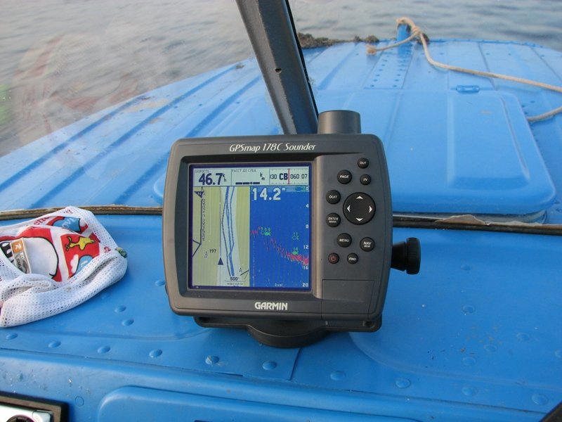
Immediately, you can see the results in the photo below, instantaneous speed and depth, everything is fine.
The lid of the relay, a layer of solid oil on the bottom, is pressed by the lid, squeezing out the air (lithol acoustic grease that does not interfere with ultrasound, otherwise air bubbles interfere) and around with silicone from a pistol so that it doesn’t dangle, water from the river into the lid and lower the sensor there - That's it. the sensor can be fixed, but I didn’t bother. Installed from 2008 to the present day without alterations.
There is also a cyanoacrylate contact complete with a primer, it holds even better
First, I glued the sensor to the silicone in the boat on the bottom under the rear seat. The sounder lied a lot, added three times the depth, the bottom and the paint layer were thick, the sounder's power was not enough (it runs on 4 batteries of 1.5 volts). So I outweighed it by transom to a clamp. I'll try to glue the eyelet onto the cyancrylate, but the contact area is very small, I can reinforce it with some kind of plastic overlays (
> I once made a sensor mount after the lugs broke
> through such a mount - the diameter is matched to the size
> sensor, let alone attach it to the clamp without any problems. Photo
> together with the sensor no - the boat has already been sold two years ago. Now
> the sensor is glued to the sealant in the Kazanka 5.
Did the metal clamp affect the operation of the sensor?
And so I'll try to attach it too! I wanted to first tie the sensor to the electrical tape to the clamp, but the clamp is naturally safer and more correct
I glued the broken sensor ear to the glue Cyancrylate contact with the primer turned out well. I did not hang the sensor on the transom yet, but tried again to glue it to the silicone on the bottom, only closer to the transom in the sub-recess niche. As a result, the depth shows correctly when the engine does not work (As soon as I start the engine, even at idle, the echo sounder readings begin to jump quickly from 0 to 40 meters, shows a bunch of fish under the boat, etc. What could it be, interference from the ignition system Does the echo sounder run on batteries, though I laid the cable from the sensor together with the electrical wiring from the battery to the dashboard, but I turned off all the devices on purpose, anyway the echo sounder shows nonsense when the engine is running. to the echo sounder, but how to do this and what kind of shielding to use? Tell me if anyone has encountered the same problem!
There was the same echo. For duralumin it is categorically not suitable.
Buy any lawrence, and you will be happy, it works well at speed, does not lie.
Thanks! So when you are fishing, it is normal, but to track depth on the go, you will probably have to buy a more serious device
Perhaps the interference from the motor is purely mechanical, namely bubbles. If so, then already at low speed (forward) it will go normally.
I wouldn't bother with electrical interference. The echo sounder operates at frequencies that are not present in the motor. Again, if the sparking noise had hit the sounder or transducer, it would be buggy earlier.
I tried it on the go, it's also buggy. Previously, when the sensor was glued to the bottom under the rear seat, it was inside the same way, only with the engine off, the depth was twisted three times.
Romanych, then there is only one way out - to present this echo sounder to the pioneers.
If, nevertheless, it is expensive, like memory, I would supplement the repair by pouring the sensor along with a clamp with something. Well, how to make such a mighty splint around the sore spot. without touching the bottom surface.

I have already prepared such an attachment for the clamp. True, there is one thought, if it does not help, then I will use the echo sounder only on fishing, without using the lookout mode)
So he is your lookout? ))))))))))))))
Then, of course, you need to fix it. I heard that lookout echo sounders cost more than one thousand American dollars.

An echo sounder on modern fishing is no longer surprising, it has become a full-fledged element of fishing equipment. However, anglers who first encounter the use of such gadgets have many questions about various aspects of their use. One of the most common is the attachment of the echo sounder transducer.
Modern echolocation devices often already contain a holder for the echo sounder transducer, but there are situations when a different solution to the problem is needed, for example:
- non-standard swimming facility;
- incompatible parameters of the instrument holder and transom;
- lack of a transom in PVC and rubber boats;
- the presence of several watercraft, different in design features;
- etc.
All transducer mounts, the so-called echo sounder sensors, can be divided into two categories according to the installation method:
- on clamps;
- on suction cups;
- permanently on glue;
- on elements floating in water.
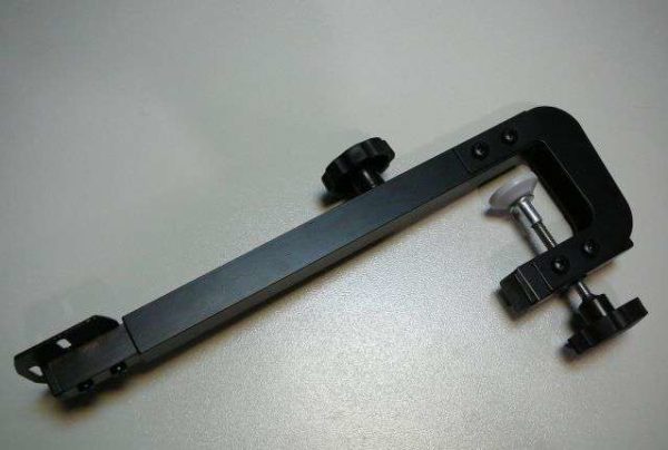
The most popular are metal echo sounder mounts, made like building clamps with rods and clamping screws. If you own a standard PVC, rubber or plastic boat, then you can probably pick up a model made by any company. If the holder of the echo sounder transducer, suitable for your set of echo sounder-boat, is not in the store, or Kulibin lives in you, you can build this important element with your own hands in your home workshop.
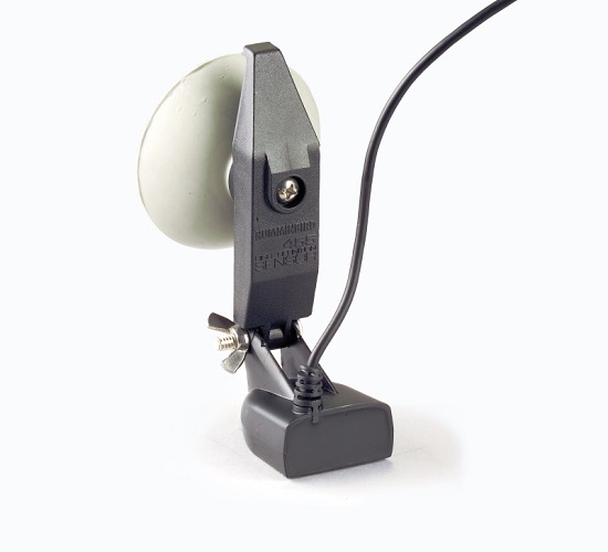
Some echo sounder models are equipped with suction cups. This mounting of the echo sounder transducer can be performed both on the boat transom and on the bottom of the boat.
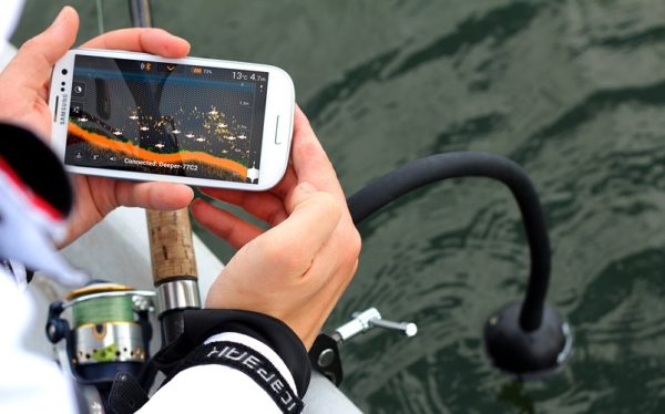
For paddle boats, we recommend attaching the sonar transducer holder to a floating object on the surface of the water, such as an irreplaceable plastic bottle.
Most of the fasteners produced are made up of three main elements:
- Clamp. With its help, the echo sounder transducer is attached to a PVC or rubber boat transom or to a plastic or wooden board.
- Bracket. Connects the clamp to the transducer mount. Allows you to adjust the height of the transducer installation.
- Assembly unit. This is where the transducer is attached to the bracket.
An additional screw is provided in the clamp to move the bracket. By loosening this screw, we can move the bracket up and down to select the best installation depth for the transducer. At the end of the bracket there are hinges or lugs for direct mounting of the transducer.
The clamp must be securely attached to the transom, excluding any vibrations of the structure in order to avoid incorrect operation of the echo sounder.
The height of the transducer relative to the water surface is very important. The fact is that when the boat moves, various water vortices are formed, and this leads to the appearance of air bubbles under water, including at the location of the sensor. But they, in turn, can lead to unpleasant consequences.
If an air gap forms between the transducer and the water, it can cause:
- incorrect operation of both the sensor and the entire device;
- incorrect display of the pattern of the investigated bottom;
- interference in the display of the picture on the display of the echo sounder.
Due to the fact that when the boat is moving, the angle between its bottom and the surface of the water changes with respect to the static position, a necessary installation condition will be the ability to adjust the angle of rotation between the transducer and the bracket. Only in this way it will be possible to accurately send the signals of the emitter perpendicular to the surface of the water.
Based on the foregoing, it is possible to formulate the necessary requirements for the installation of the transducer, this also applies to do-it-yourself structures. The echo sounder transducer holder must have:
- Reliable mount, eliminating the slightest vibration and vibrations of the sensor.
- Correction of the angle of inclination of the sensor relative to the water surface.
- Correction of the depth of installation of the transducer.
The same requirements apply to the suction cup holders. In this case, the immersion depth of the sensor can be changed by "sucking" further or closer to the water surface.
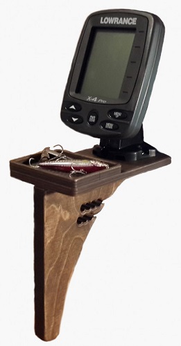
If you constantly go out onto the pond on the same vessel, then you can make the echo sounder sensor permanent by simply gluing it in the right place in the structure of the floating device. This option is possible for both PVC boats and fiberglass boats. Bonding is carried out using epoxy glue, after setting, it provides a reliable and durable connection.
For a wooden boat, you can envisage mounting the transducer on bolts or screws, additionally priming and painting the attachment point. As a coloring composition, you can use bitumen mastic or yacht varnish.
In the event that you are fishing in a calm body of water with no current and you have a rubber or PVC rowing boat at your disposal, which does not even have a transom, you can use the floating position of the transducer. Here is the sequence for making such a montage:
- We attach the echo sounder body to the bench, which the rowing boats have it. Can be mounted directly on the bench, or you can provide for any bracket.
- We attach the transducer with tape or insulating tape to the middle of the half-liter plastic bottle, and the sensor wire to its neck.
- We lower the bottle with the transducer into the water on the wire (it is strong enough and does not need additional fixation).
- Water can be used to adjust the immersion depth by pouring enough water into the bottle.
To manufacture the transducer holder you will need:
- metal-plastic pipe one meter long and 15 mm in diameter;
- a metal tube with an inner diameter of 16 mm so that the plastic pipe goes inside;
- two clamps;
- clamp;
- rubber pads, they can be cut from a bicycle tube or something similar;
- M4 bolts with washers and nuts - 4 pcs;
- cotter pin.


