In detail: do-it-yourself knight TV power supply repair from a real master for the site my.housecope.com.
my.housecope.com/wp-content/uploads/ext/2255
Posts: 7952
my.housecope.com/wp-content/uploads/ext/2255
Posts: 7952
labeg wrote:
and other optocouplers do not go.
Don't la-la! Others are coming: SFH-610A2, for example, and not only.
But in this case, the optocoupler is unlikely, because
Quote:
The power supply unit does not start up in TV Vityaz 54TTs-6010, pulses appear on the 2nd output, a voltage of 2.5 V appears on the 3rd, the pulse is output to the gate of the transistor, and after about 1 second everything repeats. The voltage on pin 3 constantly jumps from 2.5 to 1.2, on pin 6 also from 10 to 5 V. If anyone has encountered such a problem, please help.


Check 910kOm. Replace. Did you check the load?
sanek_el, check the diodes in the primary are sometimes leaking.
Good luck!


Check the resistors. As it was said 910k. and check 390k (2pcs). Better yet, change it right away, it will fly anyway.
Change resistances for 2 and 3 legs as mentioned above, for knights this is a typical defect (low quality resistance)
I changed all high-resistance resistors, electrolytes for power supply and soft start, a trimming resistor (had an open circuit), a KT3102 transistor, it still does not start, that is, it tries to start, but immediately stops, and all voltages drop. At pin 2, the voltage of 7.3 V drops to 2.2 V every second, while the supply voltage drops from 10 to 5 V. At pin 3, 2.2 V. What else could be the matter?
sanek_el, check the secondary, there may be an overload or a broken diode.
And replace the diodes (zener diode, if any) in the 4605 strapping?
Sometimes the diode breaks off at 6 feet 4605 (power supply from TPI). VD28 seems. Did you change the R 930 to exactly or did you just measure the U on the 3rd leg? It happens that when the nominal R is changed to pin 3, some U is measured, so this can be misleading. If you checked the entire hot part, turn off the secondary, load the lamp on B + should start.
| Video (click to play). |
There it sometimes breaks off on the 47th. Also 2W.
I changed the resistors on the 3 leg, 47kOhm too, I turned off the secondary systems (I dropped out the diodes), left only the diode on the horizontal scan, turned off the horizontal scan itself and put a 40 W lamp in the load. I checked it with a completely disconnected secondary, the same symptoms. Does the transformer in such TVs often fail?
Does the transformer squeak at the moment of an attempt to start?
sanek_el, turn off the load at 130 and load
light bulb


The transformer does not make any sounds, I turned off the load and loaded it with a 40 W lamp, replaced almost all the parts, and I had suspicions about the transformer, or what else could be the matter?
Is there an open circuit in the transformer windings? Is the “little white ceramic” fuse OK? Did the field worker change the microcircuit?
I join tvorcheskiy, about the field worker. Several times there were cases through his fault (probably an internal breakage). Try to change.
I changed both the field worker and the microcircuit for the second time, I did not find an open or short circuit in the windings. There is some strange thing with the microcircuit, the voltage at pin 3 is initially 2.2V, and then drops to 1.1V, it seems that this is due to the power supply, it also increases at first, and then decreases, and increases only to 10V (this is enough to power the microcircuit ?), and then drops to 5V. All voltages will jump relative to pin 7. It seems that the microcircuit begins to generate pulses, but some signal does not come from the OS and the micma stops, at this time the supply voltage is 10V. Does the transistor that closes the 3 leg to ground (KT3102) play some role in the operation of the power supply unit, or does it open only when a certain voltage level on the transformer rises?
sanek_el, “3” leg monitors the mains voltage drop. When it drops to less than 1 Volt, the microcircuit stops. The transistor monitors the increase in mains voltage. If it increases (more than normal), it will open and close 3 legs to the body. Change the resistor on the third leg to 910kOhm. And look at the diode bridge, there may be one diode in the open circuit.
Everything is in order with the damper, now I found the oscilloscope looked at the power on the 6th leg, there are sinusoidal pulses in the form of steps (about 5) with a frequency of 50 Hz (and the voltage changes from 10 to 5V in 1 s, and then also gradually increases), in the TV there is also the choke core split (maybe it is somehow connected with it?), on the second output you can see something like triangular pulses (it was not possible to synchronize), on the 5th output it looks like there are still no pulses, there just the voltage jumps along with the power supply by about 0.5V, the power supply capacitor on the 6th leg was changed
there is a start as such, otherwise the power supply unit was silent. There is no exit to the operating mode for which power on the 6th leg is required at least 7.5v. Otherwise, the power supply unit operates in the start-stop mode, as in the case of a short circuit in the secondary. Change the diode from TPI to 6 foot, as I wrote OlegK,, VD307 if I'm not mistaken.
prozba read about 4605
I beg you, I liked it there


and the cuts were burning, the holes were half-padded and single-padded
I would have seen the owner's face, I was repairing it.
I replaced the keram prex.100mk, 3102, I bought ours not ey1 but 4605-2, the field worker is not plastic (he flew away) but iron. Since the circuit without a return flow, I cut off everything, put a diode and a capacity of + 60W light bulb and everything is buzzing.
tpishki can fly too.
I hope there are no questions.
The second week I am repairing some kind of power supply, which I just didn’t do with it, I don’t want to start! I have a very high voltage at pin 6, I thought it was about the power supply, I connected an external 12V power supply, while disconnecting the 47 kOhm resistor. Now the voltage at pin 3 jumps from 0 to 2.2 s every 10 seconds. At pin 2, there is a voltage of 2.5 V, but there is no generation. There are also no pulses on the 5th pin and a very small voltage is present. The microcircuit, the entire harness for pins 2 and 3 has changed. On the filtering condenser 310, everything is as it should be. Transistor 3102 generally dropped out for the duration of the test. With its own power supply, the voltage at the 6th pin jumps, at the 3rd pin it also from 1.2 to 2.2V, at the 5th pin pulses come out with a frequency equal to the fluctuations in the power supply, their voltage is very low 0.2V. Has anyone come across something similar?
I have met. I got TV after another master. The type of field worker did not match. This is still not mentioned, and where is the guarantee that you have the right (correctly sold) field workers.
Likewise, got on fake IRF830

put the socket on 4605
buy a new 4605 (see what frequency it is designed for -2 -3 -4 -5 -6) all different
and a field worker too (this was discussed on the forum (frequency))
about statics. Do not forget.
on the way out, you can pick up the power (tel main off) (after the diode in the secondary) +12 there 2 immediately merge.
check the work of the processor.
mixAbsolutely all analogs of TDA4605 and BUZ90 work in this TV. Selection is absolutely unnecessary.
sanek_el, miracles do not happen. Sometimes you just get tired of the box. Relax a couple of days,
and then check everything in order:
- does 300v reach the field worker (you don't write about it), solder this chain well,
Perhaps on ohms it is ringing normally, but in fact it is a bad contact.
- drink trance and check by the Rottora method (10 minutes of business) - in such knights I changed
a couple of trances, but the truth is that the power supply units were launched and protection began to work
- if everything is in order, replace the entire harness in the primary, there are few details.
Note: Set the oscilloscope aside for now.
Good luck!
Look at the paths, there are cliffs. Vityaz's fees are not very good.
Solidarity with the chip was a defect, a print break under the plastic frame-like and not noticeably, but I was looking for a day.
Most likely a transformer. Rarely, but I've met.
I have a tv panasonic tc-25v70r no launch. Absolutely checked everything, help me!
temur, look at the beginning of the site topic.
Business says. For a long time nothing came out with these blocks until I took the checked 4605 from the working TV. It turned out that all my stocks of microcircuits are bullshit (Different parties). I was tormented with these 4605 until I turned blue until I realized that it was in the microcircuits.
The most unassuming turned out to be 4605-15 bought several dozen of them and all the problems were over. They start well in all schemes (ALMOST)


boldly change all high-powered 2-grip. cuts, starting with 910kom and below, sooner or later they fly
Vityaz TV malfunctions
25. VITYAZ 54TTS6411. No graphics, replacement of quartz 27000 MHz.
26. VITYAZ 51ТЦ6000-1. There is a narrow horizontal bar on the screen... There is no 26v on the vertical output chip. Breakage R128 4.7 ohm.
27. Knight 51TTS6421. On the UHF range with warming up, the setting disappears after 15-20 minutes... Replaced SKV-310L unit with KS-H-92-OL.
28. Knight 37ТЦ6024. The predominance of green in the image... Breakage of the resistor R11 120 kOhm on the "GREEN" gun on the picture tube board.
Good night!! I have such a problem, Vityaz Astra 21 TV, after turning off the TV, all channels disappeared from the off button on the TV control panel and I can't even connect a digital receiver
Hello, such a problem, I turn off the Vityaz 54CTV760-3 TV from the outlet or buttons, then I turn on the indicator back on, but it does not turn on from the remote control or from the buttons on the panel; the remote control as it should be, it is only worth turning off everything from the outlet, and you can still turn it on in the socket and pull out the plug on the board that goes to the indicator and connect the plug back everything works tell me that this is the capacity I changed
To be honest, I didn't understand anything. What is this voltage of 14 volts, 18 volts. Change the capacitors in the PSU secondary.
Is your TV, radio, mobile phone or kettle broken? And you want to create a new topic about this in this forum?
First of all, think about this: imagine that your father / son / brother has an appendicitis pain and you know from the symptoms that it is just appendicitis, but there is no experience of cutting it out, as well as the tool. And you turn on your computer, access the Internet on a medical site with the question: "Help to cut out appendicitis." Do you understand the absurdity of the whole situation? Even if they answer you, it is worth considering factors such as the patient's diabetes, allergies to anesthesia and other medical nuances. I think no one does this in real life and will risk trusting the life of their loved ones with advice from the Internet.
The same is in the repair of radio equipment, although of course these are all the material benefits of modern civilization and in case of unsuccessful repairs, you can always buy a new LCD TV, cell phone, iPAD or computer. And for the repair of such equipment, at least it is necessary to have the appropriate measuring (oscilloscope, multimeter, generator, etc.) and soldering equipment (hairdryer, SMD-hot tweezers, etc.), a schematic diagram, not to mention the necessary knowledge and repair experience.
Let's consider the situation if you are a beginner / advanced radio amateur who solders all sorts of electronic gizmos and has some of the necessary tools. You create an appropriate thread on the repair forum with a short description of “patient symptoms”, ie. for example “Samsung LE40R81B TV does not turn on”. So what? Yes, there can be a lot of reasons for not switching on - from malfunctions in the power system, problems with the processor or flashing firmware in the EEPROM memory.
More advanced users can find the blackened element on the board and attach a photo to the post. However, keep in mind that you replace this radio element with the same one - it is not a fact that your equipment will work. As a rule, something caused the combustion of this element and it could “pull” a couple of other elements along with it, not to mention the fact that it is quite difficult for a non-professional to find a burned-out m / s. Plus, in modern equipment, SMD radio elements are almost universally used, soldering which with an ESPN-40 soldering iron or a Chinese 60-Watt soldering iron you risk overheating the board, peeling tracks, etc. The subsequent restoration of which will be very, very problematic.
The purpose of this post is not any PR of repair shops, but I want to convey to you that sometimes self-repair can be more expensive than taking it to a professional workshop. Although, of course, this is your money and what is better or more risky is up to you.
If you nevertheless decide that you are able to independently repair the radio equipment, then when creating a post, be sure to indicate the full name of the device, modification, year of manufacture, country of origin and other detailed information. If there is a diagram, then attach it to the post or give a link to the source. Write down how long the symptoms have been manifesting, whether there were surges in the supply voltage network, whether there was a repair before that, what was done, what was checked, voltage measurements, oscillograms, etc. From a photo of a motherboard, as a rule, there is little sense, from a photo of a motherboard taken on a mobile phone there is no sense at all. Telepaths live in other forums.
Before creating a post, be sure to use the search on the forum and on the Internet. Read the relevant topics in the subsections, perhaps your problem is typical and has already been discussed. Be sure to read the article Repair strategy
The format of your post should be as follows:
Topics with the title “Help fix the Sony TV” with the content “broken” and a couple of blurred photos of the unscrewed back cover, taken with the 7th iPhone, at night, with a resolution of 8000x6000 pixels are immediately deleted. The more information about the breakdown you put in a post, the more chances you will get a competent answer. Understand that the forum is a system of gratuitous mutual assistance in solving problems and if you are dismissive of writing your post and do not follow the above tips, then the answers to it will be appropriate, if anyone wants to answer at all. Also note that no one should answer instantly or within a day, say, no need to write after 2 hours “That no one can help”, etc. In this case, the topic will be deleted immediately.
You should make every effort to find a breakdown on your own before you get stuck and decide to go to the forum. If you outline the whole process of finding a breakdown in your topic, then the chance of getting help from a highly qualified specialist will be very great.
If you decide to take your broken equipment to the nearest workshop, but do not know where, then perhaps our online cartographic service will help you: workshops on the map (on the left, press all buttons except “Workshops”). You can leave and view user reviews for workshops.
For repairmen and workshops: you can add your services to the map. Find your object on the map from the satellite and click on it with the left mouse button. In the field “Object type:” do not forget to change to “Equipment repair”. Adding is absolutely free! All objects are checked and moderated. A discussion of the service is here.
2.) VITYAZ 37TC 6010. The power supply does not start. Power is not supplied to m / s TDA4605. The reason is the breakage of extinguishing R137 and R135.
3.) Not often, but there are malfunctions manifested in the presence or absence of color on a part of the image. In these cases, I recommend checking the level and shape of the two-level SC pulse. So on the Vityaz 54TTS-6010 TV, there was color in PAL, and in SECAME, the color was only on the left 1/3 of the screen. The analysis revealed an underestimated level, up to about 1V, of the horizontal damping pulse of the SSC signal. The resistance R125 (100 kOhm) in the line scan circuit turned out to be faulty.
4.) Knight 54TC-6010. The TV does not turn on either from the remote control or from the front panel. S / d standby mode is on, power supply voltage is normal. The network trigger of the D4 EKR1568VG1-030 processor in the MDU-53 module is faulty. Replaced with imported analog PCA84C640P-030.
5.) Vityaz 37TC-6024 - Strong distortion of sound (there is a background of low frequency of different types, on different channels). After installing a 10 pF capacitor between the input and output of filters ZQ4, ZQ5, distortion and background disappeared.
6.) VITYAZ 54 TC 6010. The TV could work normally for a week, day, hour, but according to the owners, a malfunction periodically appeared in the form of the appearance of OX lines at the top of the screen, after which the TV went into standby mode.After restarting from the remote control everything was normal. Checking personnel gave nothing, all supply voltages were normal. The reason turned out to be in the potentiometer for adjusting the supply voltages in the power supply unit R142 (100 Ohm), it was interrupted periodically. In general, these TVs are often equipped with low-quality components. The classic defects are. 1) The TV does not turn on. Open R137, R135 in the power supply unit. 2) Sound works with noise. The reason is again in the trimmer, which stands at the input of the ULF TDA2003, I do not remember the position. Frequent malfunction.
7.) TV sets (Vityaz) where there is a digital delay line. The color of both PAL and SEKAM is missing. The defect appears when the TV is on for two hours. Repair: replace the capacitors that are on the TDA8395 7 and 8 leg.
8.) An interesting malfunction occurred in the Vityaz TV -14 inch. Outwardly, everything looked like this: the raster and sound were normal. The image was only on the left side of the screen, about 5 centimeters. The rest of the screen glowed with an even matte raster (as in video mode). Replacing the video processor (TDA8362) gave nothing. After measuring all modes for direct current (almost everything is normal) and pulse shapes, a difference in the shape of the strobe pulse was noticed. It was different from the factory one. After a detailed check and replacement of parts in the strobe formation circuit (including TDKS), which gave nothing, it was decided to change the strobe formation circuit. The TV “Horizon” scheme was taken as a basis. Alteration of the circuit for the formation of the “strobe” according to the “Horizon” gave positive results: the TV worked normally. I did not fully understand what caused the malfunction.
9). Knight 51CTV6722. Does not turn on. Broken VT402 IRFBC30 and VD408 FR156 in the power supply, after replacing the transistor KP707V1 and diode KD258V power supply appeared.
10). Knight 54CTV6742-1. No channel tuning. The SKV362D channel selector is faulty. (Faulty IC TSA5522T).
eleven). Vityaz 37ТЦ6010. Excessive image brightness. The CRT is not completely locked. Reduced accelerating voltage on TDKS.
12). Knight 54CTV6741. Adjusts to only one program. Replaced Zener diode KS531V. 875). Vityaz 51TTS6421. There is no high voltage. The power supply unit is working. There is no power on the collector of the horizontal transistor. The jumper in the connector going to the deflection coils and supplying power to the line transistor is not soldered.
thirteen). Vityaz 51TTS6421. There is no image, there is a high one. Only the channel number is displayed on the screen. The TV is always on in Window mode. The voltage on the processor is Fb = 1 V instead of 0.15 V. Replaced resistor R58 470 Ohm.
14). Knight 54CTV6721. The power supply does not turn on, does not start. A very interesting defect and very simple. All parts are in good working order and have been checked. Accidentally, when the board was turned over to the reverse side (although this happened more than once in the process of finding the malfunction), something knocked. Upon closer inspection, it turned out that the pulse transformer ferrite core had cracked, fell out onto the board and was fixed between the transformer case and the board. There was a large gap between the two halves of the core and the power supply did not start. I had to solder the transformer and glue the core.
15). Knight 54CTV6742-1. After a while of operation, the volume spontaneously adjusts and after that does not respond to buttons on the panel and on the remote control. The SDA555XFL processor in the BU-90M unit is defective.
sixteen). Vityaz 51ТЦ6421. No picture, only displays the channel number on the screen. It is switched on in the “window” mode by the signal Fb = 1 V instead of 0.15 V. The resistor R58 is replaced by 470 Ohm.
17). Knight 54CTV6742-1. Does not turn on. Broken VT402 IRFBC30 and VD408 FR156 in the power supply, after replacing the power appeared. At the output of the secondary stabilizer TDA8133 there is no output voltage of 8 V, but there is 14 V. Accordingly, R143 4.1 Ohm and IC TDA8842 burned out. After the replacement, it turned out that there was also no CD. Defective IC TDA8356. After the replacement, the TV started working.
18.) Knight 51CTV6722. On some channels, the sound and picture settings are different (the sound is not fine-tuned). Failure of the ZQ703 filter at 6.5 MHz.
19.) Knight 37TTS6010.
- does not turn on. Broken line transistor BU508AF.
- the screen does not light up. Low accelerating voltage.There is no contact in the accelerating voltage adjustment resistor in TDKS PET29-03.
20.) Vityaz 37TTS6024. Does not turn on in standby mode. The voltage at the collector of the power supply transistor is normal. Breakage of the 910 kOhm 0.5 W resistor in the power supply unit in the 3-leg divider TDA4605-2.
Do-it-yourself TV repair is a responsible business, since today a large number of different models (LCD, LSD, CRT) are presented on the market, each of which has its own technological features. Therefore, the approach to each type of TV is individual; in some cases, special skills will be required (knowledge of electronics, experience with a soldering station).
Before proceeding with the repair of television equipment, it is necessary to find out the cause of the problem.
The most common problems are:
- TV screen does not turn on - this can happen with an old picture tube screen and with the most modern television panel. Basically, this symptom is characteristic of a blown fuse. When repairing, it should be borne in mind that the appropriate fuse must be selected for each model. And also experts recommend paying attention to the diode bridge, power supply, wire, perhaps the cause of the malfunction lies in these elements. Read also what to do if Samsung TV does not turn on.
- Faint, barely noticeable picture - this kind of breakdown happens with LCD / LCD monitors. The most likely cause of the malfunction: faulty diodes, device backlighting.
- There is no sound, the screen "wheezes" - most likely, the sound amplifier or microcircuit is out of order. Also read what to do if there is sound, but there is no picture.
- Monitor is on, no picture - Perhaps the cause of the problem is in the video processor or in the receiving unit.
You should be aware that if a darkening of the board or rupture of elements is detected during a visual inspection of television equipment, then it is not recommended to immediately start replacing parts. Since such factors indicate a short circuit that could have occurred in another section of the TV. Therefore, if you do not eliminate the cause of the short circuit, but simply change the failed elements, then the situation will repeat itself.
To repair television equipment, the following tools and equipment may be required:
- Screwdriver Set;
- hex keys (in rare cases);
- pliers;
- soldering station (for repairing modern monitors);
- screen layout (can be downloaded on the Internet);
- multimeter;
- oscilloscope.
Many LCD screen problems can be dealt with on your own. But you should know that these screens require more careful handling than, for example, CRT TVs.
First of all, the user needs to study the instructions for his model, and only after that start repairing the LCD or LED screen. You should be aware that LCD TVs use fluorescent bulbs for backlighting, while LEDs use LEDs.
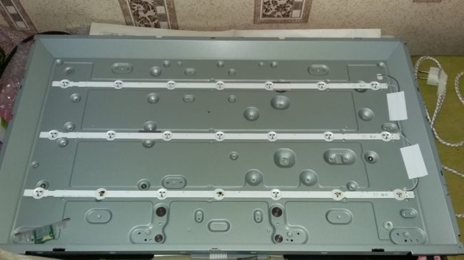
The TV may not function due to lack of power, to check this, you need to do the following:
- Open the back cover of the LCD TV with tools.
- Disconnect the wires that are connected to the device matrix.
- Connect a working light bulb to the contacts.
- Some panels have more than one light source, in which case they must be tested as well. This can be done as follows: pull out the TV matrix and connect it to the network, it will immediately become clear which lamp is out of order.
After the faulty luminaire is found, it must be replaced. This procedure should be carried out as carefully as possible. In most cases, the lamp can be taken out even without removing the matrix - you need to move the protection elements aside and take out the burned-out part using a soldering station. Then a new lamp is installed in the same way.An important rule is that the new lamp must be completely identical to the old one.
Another common problem with these models is damage to the monitor. But in this case, it is not advisable to repair LCD TVs, since it is easier to buy a new screen. This test scheme can also be used to repair plasma televisions of all types. Read also how to fix the LED backlight yourself.
Each manufacturer has its own weak points, so below is a selection of the most common LCD screen breakdowns.
Often, users of this brand are faced with such a problem that when turned on, the device beeps without interruption. This symptom usually indicates that a leak has occurred. It is recommended to try replacing the preout stage diode.
Another common problem is that the monitor turns on and off itself. The main reason for this breakdown is a failed transistor, it is necessary to replace it. It is recommended that such malfunctions be eliminated on their own only by people who have experience in repairing television equipment.
DIY Philips TV repair is recommended if the problem is minor: settings are lost, cable replacement is required.
If the breakdown is complex, then it is better to entrust its elimination to specialists who will not only professionally perform repairs, but also issue a guarantee. Therefore, if the repaired screen stops working again, the user may demand a refund.
LG flat screen owners may have a problem saving settings. Such a problem does not require contacting the masters, you can repair the LG TV yourself. It is enough to switch the device to another operating mode, and all settings will be saved.
As well as in the case of other LCD models, if the problem is serious, then it is not recommended to repair an LG TV with your own hands, it is better to contact a specialist.
Despite the fact that today most consumers prefer the most modern plasmas, CRT screens are still in demand. These TVs have their advantages: they are inexpensive, easy to operate, and the quality of the transmitted picture is still high.
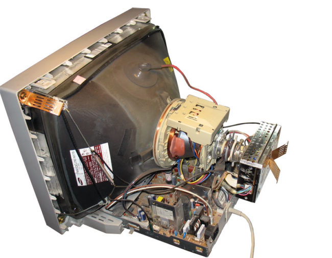
The main problems with CRT devices:
- the CRT TV does not turn on - just like on devices of a different type, first of all, you need to check the integrity of the fuses;
- a diode bridge malfunction is a common problem with CRT receivers, you can fix the TV only after making a "ringing", you will need a multimeter from the equipment;
- breakage of the posistor is considered the most serious problem; in order to check, it is necessary to turn off the power circuit of the TV, then start it again. After, observe the lamp, if it goes out, it means that the posistor is out of order. First of all, you need to adjust the resistance of the network, and then replace the part;
- burnout of a transistor or capacitor - such a malfunction can be easily replaced by visual inspection (on black carbon parts), repair is carried out by replacing the part.
Below is a list of problems encountered by owners of CRT TVs.
- The Rubin TV buzzes loudly when connected - most likely, the photodetector needs to be replaced.
- The ruby does not turn on, the indicator does not light up - voltage surges in the transistor.
- The Horizon TV does not have a blue tint, as well as the white balance is disturbed - this is mainly due to a broken resistor.
- There is sound, no image - the cause of the problem lies in poor contact of the power connector of the screen board. It is recommended to use a soldering iron to solder the harness into the Horizon TV board.
- The screen does not turn on - there is a problem with the power supply.
- A horizontal strip appears on the monitor - repairing a Vityaz TV consists in fixing a problem in the frame scan microcircuit.
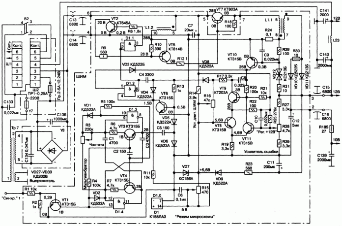
Since the malfunction of the power supply is one of the most common problems of all types of TVs, it is necessary to study it in more detail.
Since all models of LCD monitors do not have fundamentally different design differences, the diagram below can be applied to all TVs (Toshiba, Horizon, Samsung, Sony, Rubin).
Repair of monitors equipped with a picture tube, for example, such as (ruby, sharp 2002sc, sony trinitron, vvk), as well as repair of Samsung TVs, Panasonic. always starts checking the power supply.
Testing is carried out using an incandescent lamp, but before performing the procedure, it is necessary to disconnect Sharp c2002sc, Samsung or another screen from the load (horizontal cascade). The horizontal scan voltage can vary from 110 to 150 V, it depends on the size of the picture tube. It is required to find a sweep filter capacitor in the TV circuit. Next, you will need to connect a light bulb, in order to remove the load, it is necessary to unsolder the choke and the fuse through which the JV element consumes power. This scheme is used for sharp screens since 2002sc.
| Video (click to play). |
After that, connect the power adapter to electricity and measure the voltage, if the values exceed the norm, you will have to check the feedback circuit of the power supply. If the power supply unit is in good condition, then the light bulb is removed and all the elements are soldered into place. This is the basic information on how to repair a TV with your own hands.

