In detail: do-it-yourself hammer grinder repair from a real master for the site my.housecope.com.
As you know, nothing is eternal and even the tools of brand manufacturers break, not to mention the so-called “consumer goods”. And the grinder (angle grinder) is no exception. By the way, they began to call angle grinders "grinders" at the time of the Union, because then this instrument was produced in Bulgaria and the first models were supplied from there. The grinder, as a tool, has become very widespread due to its versatility and ease of use. There are also many varieties and models of grinders, but the principle of operation and device is not fundamentally different. Therefore, having considered the device of the tool, possible malfunctions and repair methods, they can be applied to any model of the grinder.
Grinder device relatively simple. The basis of the tool is its body, inside which there is an electric motor, a starting device and a gear transmission to the spindle, on which various attachments are attached.
The body is made of strong impact-resistant plastic. Depending on the power, there are different dimensions and shapes of the tool. Some models have an angular speed regulator, which is designed to optimally select the speed for various types of work.
Another component could be a gearbox. The gearbox is designed to create optimal conditions for the transfer of rotation from the rotor of the electric motor to the cutting or grinding wheel. This leads to a decrease in the number of revolutions on the output shaft of the gearbox. Correctly selected rotational speed and wheel diameter are the key to the most efficient tool performance.
| Video (click to play). |
A button for replacing the working disk, when pressed, which locks the disk in a certain position, preventing it from scrolling when removed.
The overload clutch acts as a limiter in the event of a sudden reactive torque. On the other hand, when the disc is jammed in the material, the grinder itself begins to rotate abruptly, which can lead to injury to the worker. This clutch does not allow such rotation.
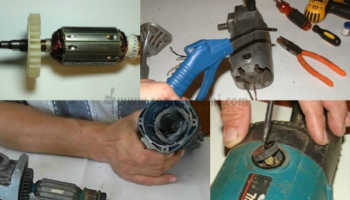
The electric motor consists of a stator and a rotor as standard. The stator is located in the guide lugs of the plastic housing of the grinder. On the back of the stator there is a special device called a brush mechanism. It contains copper-graphite brushes. Brushes are required to transfer voltage to the rotor through the manifold assembly.
The rotor is located inside the stator and is fixed in the housing in bearing assemblies, which are inserted directly into the tool housing. The front bearing assembly is usually made in a metal plate, or this plate can be made of an aluminum alloy.
The gearbox housing of the grinder is almost always made of aluminum alloy and has several threaded holes for attaching an additional handle. By screwing the handle into various holes, you can change the planes of location during operation.
The reducer consists of two gears, with the help of which the direction of the output shaft changes by 90 degrees and the rotation speed is reduced. The ratio of the number of teeth on the primary gear to the number of teeth on the secondary gear is called the gear ratio.
The grinder suddenly stopped working.
The first thing to do is disconnect physically from the network and manually rotate the disc. If the disc does not spin or is spinning very tightly, immediately disassemble the instrument for visual inspection. If it turns easily, then the most likely thing is that electricity does not reach the brushes of the electric motor.That is, the problem lies either in the power plug, or in the wire itself, or in the mechanism of the “Start” button. It is enough to disassemble the case and “ring out” the cable with an ordinary tester, or in some other way, for the presence of a break. After eliminating the break or replacing the wire, the grinder will work.
The wire and plug are guaranteed to be intact, but the tool still does not work.
It is necessary to disassemble the trigger mechanism, and it is advisable to mark the removed contacts - if they are subsequently connected incorrectly, then the winding may burn out or the anchor may jam. Repair of the trigger mechanism is not often possible - it is easier and more reliable to replace the trigger button with any similar one with suitable power parameters. Such a button is not so expensive and you can buy it in any store of the corresponding profile.
The start button and the power wire are in working order, the grinder does not work.
Check brushes and brush holders. There may be a breakage or complete wear of the brushes. The resource of these devices is usually limited to several years, of course, it all depends on the intensity of use. Eliminate open or replace brushes.
Then there are more serious malfunctions, respectively, and repair requires certain knowledge and skills.
- breakage or licking of the gear teeth of the gearbox;
- jamming of bearings;
- failure of the armature or stator;
- failure of the control electronics;
- failure of the collector;
- deformation of the body;
When determining the mechanical defects of the grinder, more attention should be paid to the condition of the plonitarka (large gear), shank (gear on the shaft) and bushings. Uneven wear of the teeth or wobbling of the shafts indicates immediate replacement of the worn parts.
Breaking out the spindle lock button.
The reason is just one careless movement, namely pressing (deliberate or accidental) on the button when the disc is spinning. Sometimes breakdowns occur due to attempts to remove a jammed disc using a button. Many grinders have slots on the spindle where the disc is attached specifically for a regular open-end wrench, look at your grinder, most likely you have one too. So, it is better to use them and an open-end wrench than a disc lock button.
Chipped gear teeth.
Usually they arise due to jamming (in such a situation, tool breakage is not the worst thing that can happen). A rumble in the gearbox is a sign of a malfunction. If the gear has lost two or three teeth, then the tool will not be able to cut.
In this case, it is necessary to change the gears by a pair and the gear itself and the bevel wheel. When you go to the store for gears, do not forget to write down the name of your grinder and its power.
Failure of the electric motor.
This often happens with tools that work in dust and which are forced to rest in the sand or on the ground: the sucked-in dust grinds off the winding. However, you can ditch the motor without dust - by strong overloads, especially if the tool is low-power. Therefore, in small Bulgarians, not only the anchor, but also the stator often burns out. Small grinders also have a breakdown of the electronic speed control unit. If you use a grinder to cut very dusty materials, in particular slate, a stocking put on in place of the ventilation slots in the housing helps a lot to protect the tool.
Bearings.
Another sore spot of the Bulgarians (as well as other twisting power tools). Few machines stand out with strong immunities against dust, and high rpm suggests rapid wear. In general, bearings are not the worst failure, they are easy to change. However, it is important to make a replacement on time, otherwise there is a greater likelihood of a more serious breakdown, the repair of which is comparable to a purchase.
Stator
If, when turned on, the disk starts to gain speed and accelerates too much, there is definitely a turn circuit on the stator winding.Stator repair is one of the most serious breakdowns and requires appropriate skills. If you are not confident in your abilities, then it is more expedient to entrust it to professionals or use the services of a repair shop.
We start repairing the grinder's stator by cutting off the frontal parts of the winding, the remnants of which we take out. Next, we make a new winding using a template sandwiched between two large plates on an axis, which can be inserted into an electric drill. The main thing is to achieve an identical number of turns, made with the proper density and withstand the thickness of the wire. We insert two coils into the stator housing, we draw conclusions from the same winding wire, insulating with flexible tubes of the appropriate diameter.
Reducer
In models with a power of up to 1100 W, spur gears are usually used, mounted on an anchor, but grinders with a higher power, for example, 1500 W, require helical gear wheels. Both options are tapered, since the axis of the gearbox stem intersects with the armature shaft, and transmission is possible only by angular engagement of the teeth.
As a rule, repairing the grinder's gearbox consists only in replacing the gears. If a disk gear wheel breaks down, then it will be very difficult to remove it for replacement, this unit is best fixed in the gearbox.
Speed regulator
Almost all modern models of drills, jigsaws, screwdrivers have a speed controller. But not all grinders (grinders) are equipped with such a mechanism. In principle, a regulator is not needed for cutting metal with a cut-off stone, but for grinding it simply cannot be replaced. The proposed scheme of a home-made regulator is very simple and reliable. There are not many parts and they are not expensive. If you already have a grinder without a standard speed governor, then you can easily improve it.
Can be assembled separately in a box with a power outlet and used as a carrier with a power regulator. Or you can immediately assemble the regulator in the grinder body and remove the resistor handle.
The power tool must not be allowed to operate under load for a long time at significantly reduced speeds (this can be determined by ear) in comparison with idle speed, and even more so, clamping (blocking) of the tool must not be allowed, otherwise it will burn out within a few seconds.
Do not turn off the power tool immediately after operating at reduced speed. To prevent local overheating, it needs to run for some time (more than 1 minute).
It is important to strictly observe the intervals for changing (adding) the lubricant and its quantity specified in the operating instructions.
Prevention consists in complete or partial disassembly of the tool, cleaning, lubrication and replacement (if necessary) of some parts.
Timely replacement of relatively cheap parts that wear out quickly will preserve more expensive durable components, which ultimately will lead to savings in tool operation, eliminate premature repairs and significantly extend the life of the tool.
The grinder, being the most demanded tool in the house, is subject to considerable stress and intensive use. Because of this, after some time, it happens that when the engine is started, jerks, a burning smell and other malfunctions appear, suggesting that the angle grinder (angle grinder) has broken down. But do not immediately carry the device for repair or buy a new one. Most faults in this device can be rectified by yourself.
Over the long years of the existence of such a tool as angle grinder, its appearance, as well as its internal structure, have practically not changed. To repair a grinder with your own hands, you need to know the structure of its mechanical part, as well as electrical.
If you look at the figure below, you can see what parts the angle grinder consists of.
- Wheel for adjusting the spindle speed of the unit.
- An electric motor consisting of a rotor and a stator.
- Start button. Sometimes a soft start system is connected to it.
- High impact plastic housing.
- Spindle lock button (used when changing tools).
- Safety clutch. Protects the motor from overload when the tool is jammed.
- Protective cover. Covers the tool and protects the user from escaping particles of the processed material, and also prevents injury to a person when a tool is destroyed, such as an abrasive disc.
- Tool clamping nut. It can be unscrewed using a special key that comes with the power tool. There are also quick-locking nuts that can be unscrewed without a wrench.
- The gearbox housing and the gearbox itself. Consists of a block of gears that transmit rotational movements from the rotor to the spindle with the tool.
The picture below shows electric diagram of the grinder.
The electrical part of the angle grinder has the following elements:
- electric cable with a plug for connecting to the mains;
- start button;
- stator;
- electric brushes (carbon or graphite);
- collector;
- anchor (rotor).
The following figure shows grinder connection diagram, namely its engine.
All components of an electric motor perform specific functions.
- Rotor - this is the shaft on which the coils and the collector are located. The rotor, rotating in the magnetic field of the stator, transmits the rotational motion to the angle grinder.
- Collector... It is the part of the rotor to which all control cables are connected. Electrical signals from the control unit to the engine pass through the manifold. It is to the collector that the electric brushes are connected.
- Electric brushes. Their main task is to transfer electric current from the power cable to the collector.
- Stator. It is a coil with a certain number of turns. The task of the stator is to create a magnetic field, which, interacting with the armature, sets the latter in motion.
According to statistics, most cases of failure of angle grinders are associated with the electrical part of the apparatus. Some breakdowns may be minor, which allows you to repair the grinder yourself. But, for example, if the motor windings burn out, only a specialist can repair the angle grinder.
The reasons that the angle grinder does not turn on may be the following:
- defective electrical plug;
- defective electrical cable;
- the start button has broken;
- broken contact between the power cable and the button;
- breakage of the contact wire of the electric brush;
- strong wear of the electric brushes;
- failure of the rotor or stator windings.
There may be different reasons for the angle grinder not picking up speed.
- Breakage of the speed control unit... To test this version, it is necessary to connect the engine of the device directly, bypassing the regulator, and check the operation of the device.
- Faulty electrical cable due to constant bending or mechanical damage. Because of this, the damaged wire begins to warm up under load, and the engine speed drops.
- Dust contamination of the collector... Remove contamination with alcohol.
- Brush problems... They may wear out or have a short contact wire, as shown in the following photo.
The brush, although half worn out, is quite functional. In this case, the short contact wire prevents the spring from pressing the electrode against the collector. This situation can also be the reason why the angle grinder stopped working in normal mode.
The reasons why the grinder is heating may be as follows.
- Incorrect mode of operation of the device... As a result of overloads, the electric motor can become very hot, which often leads to burnout of the windings.
- Bearing failurelocated at anchor. As a result, the rotor clings to the stator, the motor becomes difficult to operate, and the windings overheat. The problem is solved by replacing the bearings.
- Clogged ventilation ductsthrough which air enters to cool the engine. It is necessary to clean the ventilation openings from dust.
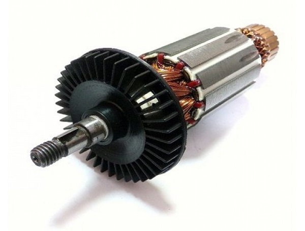
If you notice strong sparking when turning on the angle grinder in the place where the collector is located, then the reasons for this trouble may be as follows.
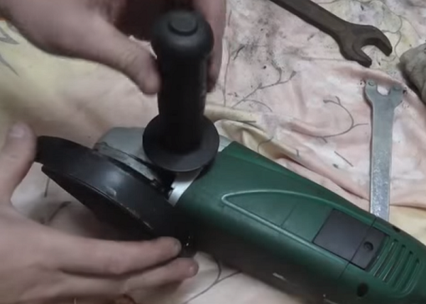
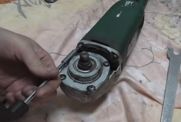
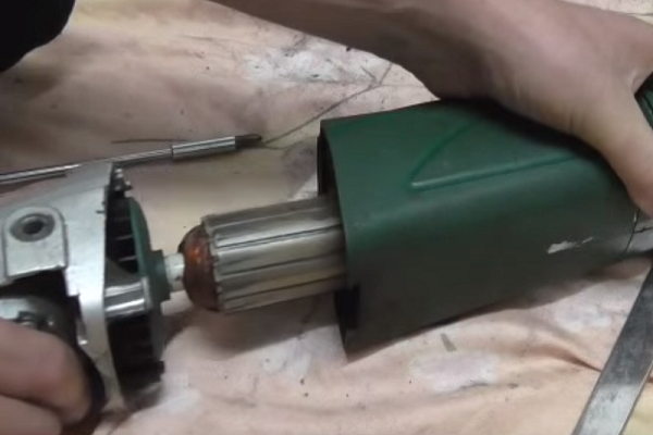
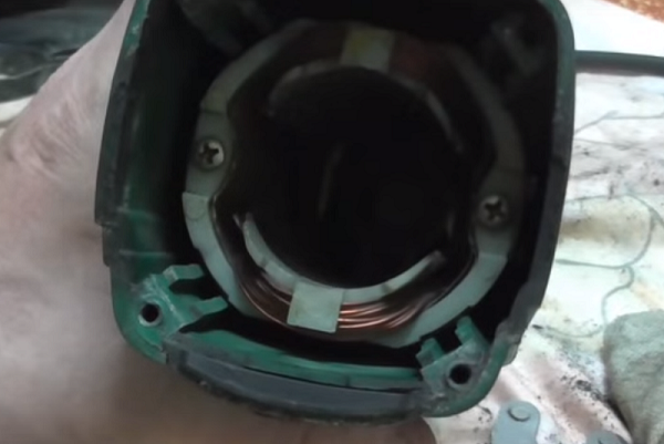
To diagnose the electrical part of the angle grinder, as well as eliminate mechanical damage to the device, you will need to disassemble it. Disassembly is carried out according to the following algorithm.
-
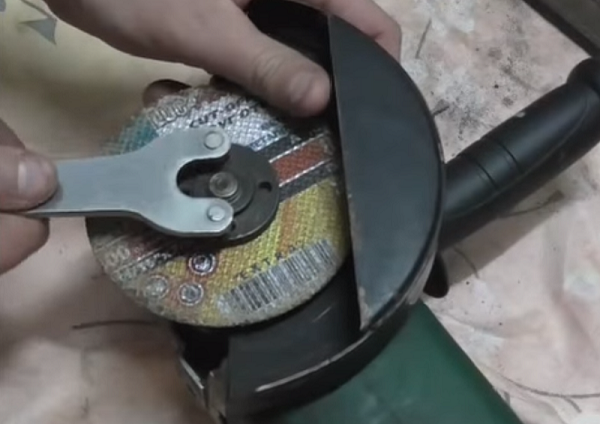
Using a wrench, remove the disc or other attachment from the spindle of the unit.
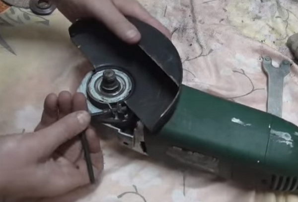
Unscrew the handle.
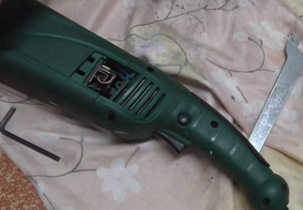


As mentioned above, most often the angle grinder refuses to work due to breakdowns in the electrical part of the unit. For the correct diagnosis of the electrical circuits of the instrument, the repairmen of electrical equipment use a special device - tester.
If you pressed the start button of the unit and it does not work, then in 90% of cases the cause of the breakdown is not so serious that you cannot repair the grinder yourself.
Experts advise adhering to the basic rule of repairing a power tool: move from simple to complex.
The first step is to checking electrical cable and plug at its end. If it is collapsible, then unscrew it and check the reliability of the contacts. Otherwise, you will have to disassemble the grinder (remove the cover of the device) and “ring” the cable with a tester, and also make sure that the current goes to the contacts of the “Start” button. If the device shows a break, then the cable should be replaced with a new one.
The situation when the current flows to the button, but does not pass further (when the position is on), indicates switch malfunctions... The button cannot be repaired. It must be replaced with a new one, but first mark the removed contacts in order to connect them correctly in the future. If the contacts are incorrectly connected, the motor winding may burn out.
If during the check it turned out that both the cable and the start button are in good order, but no current flows to the brushes, then it is necessary to make cleaning the contact plates of the brush holders... If this procedure is ineffective, it is recommended to replace the brushes. Further, if everything is fine with the brushes, and the current flows to them, the rotor and stator should be checked for shorts and breaks.
The rotor of the electric motor may have the following faults: interturn short circuit and wire breakage at the contacts of the lamellas. You can check the grinder's anchor with a multimeter: the device is switched to the resistance change mode, the value is set to 200 Ohm, and the resistance between two adjacent lamellas is measured with the help of probes. Thus, it is required to check all pairs of lamellas. If the resistance values are the same, then the rotor winding is not damaged.The detection of other resistance values during the “ringing out”, as well as the detection of an open circuit, indicates a malfunction in this coil. In this case, you will need to repair the grinder's anchor.
Usually, the break of the conductors occurs at the junctions with the winding. Inspect the places where the coils are connected to the lamellas, make sure that the contacts are soldered securely.
If you do not have a measuring device, then you can check the rotor by using 12 V light bulb and battery... The power should be between 30-40 watts. The check is done as follows: apply a voltage of 12 V from the battery to the plug of the angle grinder, connect a light bulb to the break of one wire, start rotating the spindle of the angle grinder. If the winding is in good condition, the light will burn evenly, without blinking. With an inter-turn closure, the degree of incandescence of the spiral of the light bulb will change. In this case, repairing the grinder's anchor with your own hands will be difficult, since the anchor winding scheme is quite complicated, and the process itself requires special equipment and knowledge. Therefore, it is recommended to entrust this operation to specialists. But the best way out of the situation would be to replace the anchor on the grinder with a new one.
If the light does not light up when testing the rotor, this indicates the presence of an open in the stator or a short circuit in its windings, as well as problems with the electric brushes.
To check the stator of the grinder, use, as in the previous case, a multimeter. The values you need set to 20-200 Ohm and do the following. Touch one probe to the contact of the stator winding, and the second to the body of the part. If the device shows resistance, it means that there has been a breakdown to the case. Touch the probes to the contacts of one winding, and then to the contacts of the other. If the resistance is the same, then the coils are serviceable. If the device shows an open circuit on one winding, it means that you will need to rewind the stator or replace the part with a new one.
It will be problematic to rewind the stator at home without special knowledge, skills and equipment. It is better to contact a specialist who is professionally engaged in motor rewinding.
Mechanical breakdowns of angle grinders include the following.
Mechanical failures include breakage of the shaft retainer. In order to replace the retainer, you will need to disassemble the gearbox and remove the large gear.

