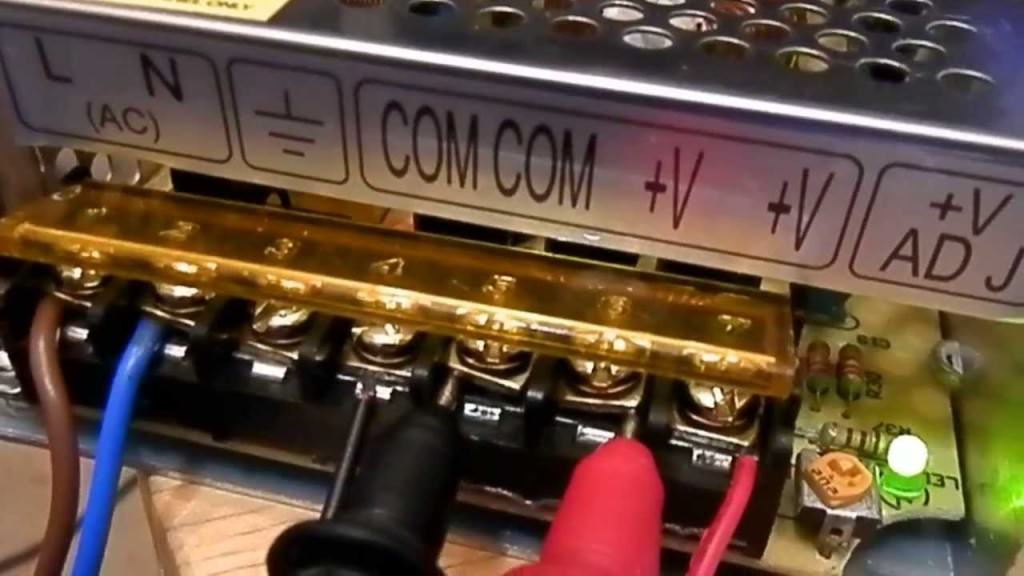
In detail: DIY TV repair from a real master for the site my.housecope.com.
Most modern consumer electronic equipment has in its design independent or located on a separate board electronic modules that reduce and rectify the mains voltage.
There are several reasons for this, but the main ones are:
- fluctuations in the mains voltage, for which these step-down-rectifier devices are not designed;
- non-observance of operating rules;
- connecting a load for which the devices are not designed.
Of course, it can be very offensive when you need to do urgent work, and the power module of the computer is faulty, or while watching your favorite TV show, this device fails.
Do not immediately panic and go to a repair shop or rush to an electronics supermarket to purchase a new unit. Often the reasons for inoperability are so trivial that they can be eliminated at home, with minimal expenditure of financial resources and nerves.
Of course, in order to try not only to repair the switching power supply, but also to determine its malfunction, you must have basic knowledge of electronics and have certain electrical skills.
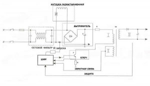
As part of any power supply, whether built-in, like in a TV or installed as a separate device, like in a desktop computer, there are two functional blocks - high-voltage and low-voltage.
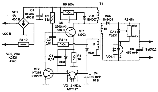
In the high-voltage side, the mains voltage is converted by the diode bridge into a constant voltage, and smoothed on the capacitor to the level of 300.0 ... 310.0 volts. Constant, high voltage is converted into a pulse voltage with a frequency of 10.0 ... 100.0 kilohertz, which makes it possible to abandon massive low-frequency step-down transformers, replacing them with small-sized pulse ones.
| Video (click to play). |
In the low-voltage unit, the impulse voltage is lowered to the required level, straightened, stabilized and smoothed out. At the output of this unit, there is one or more voltages required to power household appliances. In addition, various control circuits are mounted in the low-voltage unit, which make it possible to increase the reliability of the device and ensure the stability of the output parameters.
Visually, on a real board, it is quite easy to distinguish between the high-voltage and low-voltage parts. The network wires are suitable for the first, and the supply wires go from the second.
A person who is going to try to repair a power supply unit for household electronic equipment must be prepared in advance that not every power supply device can be repaired. Today, some manufacturers produce electronics, the blocks of which are not subject to repair, but complete replacement.
Not a single master will undertake the repair of such a power supply unit, because initially it is intended for the complete dismantling of the old device with replacement with a new one. Often, such electronic devices are simply filled with some kind of compound, which immediately removes the question of its maintainability.
As statistics show, the main malfunctions of the power supply are caused by:
- malfunction of the high-voltage part (40.0%), which are expressed by the breakdown (burnout) of the diode bridge and the failure of the filter capacitor;
- breakdown of a power field-effect or bipolar transistor (30.0%), which forms high-frequency pulses and is located in the high-voltage part;
- breakdown of the diode bridge (15.0%) in the low-voltage part;
- breakdown (burnout) of the choke windings of the output filter.
In other cases, the diagnosis is quite difficult and without special devices (oscilloscope, digital voltmeter) it will not be possible to perform it. Therefore, if the malfunction of the power supply is not caused by the four above-mentioned main reasons, you should not engage in home repairs, but immediately call a master for replacement or purchase a new power supply device.
Faults in the high-voltage section are easy enough to detect. They are diagnosed by a blown fuse and a lack of voltage after it. The third and fourth cases can be assumed if the fuse is good, the voltage at the input of the low-voltage unit is present, and the input voltage is absent.
It is advisable to check all the details at the same time. If several electronic elements are burned out, when one of them is replaced with a serviceable one, it may burn out again due to a complex malfunction that has not been eliminated.
After replacing parts, you must install a new fuse and turn on the power supply. As a rule, after this, the power supply begins to work.
If the fuse has not blown, and there is no voltage at the output of the power supply, then the cause of the malfunction is the breakdown of the rectifier diodes of the low-voltage part, the burnout of the inductor or the output of the electrolytic capacitors of the secondary rectifier unit.
Malfunction of capacitors is diagnosed when they are swollen or fluid leaks out of their body. The diodes must be evaporated and checked with a tester in the same way as checking the high-voltage part. The integrity of the choke winding is checked by a tester. All defective parts must be replaced.
If you cannot find the desired choke, then some "craftsmen" rewind the burned-out one, picking up a wire of a suitable diameter and determining the number of turns. Such work is quite painstaking and is usually performed only for unique power supplies, it is difficult to find an analogue for which.
As already mentioned, most power supplies for modern computers and TVs are built according to a typical scheme. They differ in the size of the electronic parts used and in the output power. The diagnostics and troubleshooting procedures for these devices are identical.
However, a high-quality repair requires an appropriate tool, the range of which includes:
- soldering iron (preferably with adjustable power);
- solder, flux, alcohol or refined gasoline (Galosha);
- device for removing molten solder (desoldering pump);
- Screwdriver Set;
- side cutters (nippers);
- household multimeter (tester)
- tweezers;
- 100.0 watt incandescent lamp (used as ballast load).
In principle, simple TVs can be repaired without a circuit, but the main difficulty in repairing some models is that the power supply device generates the entire range of voltages - including the high-voltage used to scan the kinescope. The power supplies for household computers are made according to the same type of scheme. Let us consider separately the methodology for determining the malfunction and repairing the TV and desktop.
A malfunction of the TV power module is first of all evidenced by the absence of a glow of the "sleep" mode diode. The first repair operations are:
- check for the integrity (absence of breakage) of the supply voltage cord;
- disassembly of the television receiver and release of the electronic board;
- inspection of the power supply board for the presence of externally faulty parts (swollen capacitors, burnt spots on the printed circuit board, burst cases, charred surface of resistors);
- checking the soldering points, with special attention paid to soldering the contacts of the pulse transformer.
If it was not possible to visually establish the defective part, then it is necessary to sequentially check the performance of the fuse, diodes, electrolytic capacitors and transistors.Unfortunately, if the control microcircuits are out of order, their malfunction can be established only indirectly - when, with completely serviceable discrete elements, the operational state of the power supply does not occur.
The most common reasons for the inoperability of television units are:
- breakage of ballast resistance;
- inoperability (short circuit) of the high voltage filter capacitor;
- malfunction of the secondary voltage filter capacitors;
- breakdown or burnout of rectifier diodes.
All these parts (except for rectifier diodes) can be checked without removing them from the board. If it was possible to identify the faulty part, then it is replaced and they begin to check the repair performed. To do this, an incandescent lamp is installed in place of the fuse and the device is connected to the network.
Several options for the behavior of the repaired device are possible here:
- The light flashes and goes out, the sleep mode LED lights up, a raster appears on the screen. In this situation, the line scan voltage is measured first. If its value is too high, it is necessary to check and replace electrolytic capacitors with guaranteed serviceable ones. A similar situation manifests itself in the event of a malfunction of the optocouplers.
- If the lamp flashes and goes out, the LED does not light up, the raster is absent, then the pulse generator does not start. In this case, the voltage level on the electrolytic capacitor of the filter of the high-voltage part is checked. If it is below 280.0 ... 300.0 volts, then the following malfunctions are most likely:
- one of the rectifier bridge diodes is broken;
- large capacitor leakage (the capacitor is "old").
If there is no voltage, it is necessary to re-check the continuity of the supply circuits and all diodes of the high voltage rectifier.
The above sequence and test scheme allow you to identify the main malfunctions of the power supply device of the television receiver.
Today, ATX devices of various capacities are most widely used for powering desktop (desktop) designers. The reason for their repair should be:
- the motherboard does not start (the computer is completely inoperative);
- the cooling fan of the device itself does not rotate;
- the block “tries” to start itself many times.
Before starting the repair of ATX devices, it is necessary to assemble the load circuit (figure). The repair is carried out in the following sequence:
- the device is removed from the computer and the cover is removed from it;
- a vacuum cleaner and a brush removes dust from electronic boards and surfaces of parts;
- external examination of electronic elements and printed circuit boards;
- a load device is connected.
If, when turned on, the lamp flashes brightly and continues to burn, then the diode bridge in the high-voltage part or the filter capacitor is out of order. Burnout of the high-voltage transformer is possible.
If the fuse is intact, then the reason for inoperability may be:
- failure of the transistors of the pulse generator;
- malfunction of the PWM controller.
In these cases, it is easier to purchase a new device, which, depending on the capacity, costs from 600 to 800 rubles.
With repeated self-starting of the device, the reason for inoperability is usually the failure of the reference voltage stabilizer. In this case, the computer system cannot pass the self-test mode, it turns off and turns on the power module.
Photo of the TV power supply
Among all the malfunctions, the repair of power supplies takes the first place. In the article "TV Power Supply Malfunctions" I described typical power supply failures. In this article I want to describe the work and repair of power supplies in more detail.
You probably need to start with how to check the power supply after repair, so as not to cause it to break again. Although this method is considered controversial, I find it very effective.
So after repairing the power supply, you need to solder a 150 watt light bulb into the fuse break (it can be 100, but there may be a false glow), and solder the light bulb into the B + circuit break (line scan power 95-145 volts, you can simply cut the track) 40-60 watts. Please note that some power supplies will not start at light load.
This system works like this. When you turn on the network after repairing the power supply, if it is working properly, the first light bulb at the moment of charging the network capacitor (100-220μF 450V) lights up and goes out as it charges. A weak glow remains. A 60-watt light bulb glows according to the voltage in the floor.
With a faulty power supply, a 150 W lamp glows with full incandescence. In some cases, this saves the transistor, microcircuit from repeated failure of key elements.
In the second method, the power transistor of the power supply is not soldered and the level and shape of the signal coming to it is analyzed with the help of instruments (oscilloscope, multimeter).
In the description, I will rely on the diagram below.
Malfunctions can be caused by:
We check for a short circuit the elements of the mains filter, rectifier, thermistor - demagnetization system, the key and its strapping elements, as well as the key microcircuit (if the power supply is built on it).
When you find a faulty element, analyze the reasons for its failure. Failure of the transistor can be caused both by a voltage surge in the network, and by drying out of capacitors in the primary circuits.
The power supply does not turn on, the mains fuse is intact.
It should be checked for breakage: mains filter, rectifier, PWM - modulator.
Start by checking if the mains capacitor C has a constant voltage of about 300V (if not, look for a break in the mains filter, and also check the resistor R.
If there is + 300V on the capacitor C, check if it reaches the key transistor. You should also check the primary winding of the TP mains pulse transformer for breakage.
If all the elements are in good working order, and the power supply does not turn on, it is necessary to check the arrival of pulses to the base (gate) of the transistor.
Also check the trigger R circuitry, usually high resistance resistors.
Check: the elements of the secondary rectifiers of the power supply, the loads of the power supply for a short circuit, the elements of the protection system (monitoring circuits for the output voltages), feedback circuits (modulator).
With the secondary circuits and their loads, I think everything is clear, it is necessary to check the rectifiers (diodes) and filter capacitors.
In the protection circuits, check the optocoupler and its piping.
With regards to the feedback circuits, check the zener diodes, diodes, capacitors (usually 4.7-10- 47 microfarads).
Network capacitor, capacitors of the PWM strapping, serviceability of the optocoupler and its strapping.
In this case, proceed as follows:
- check the soldering of the power supply elements for ring cracks;
- check the elements in the hottest places on the board by identifying them by blackening.
- In the event that a malfunction manifests itself when the TV is warming up, it is possible to localize the defective element either by cooling (cotton wool soaked in acetone, alcohol), or to speed up the occurrence of a malfunction by provoking it by heating one or another element with a soldering iron.
Hello! Please help me choose an analogue power supply unit (Wene-wn220a-3 24V 7A) for the Chinese TV no. Found one similar to ebay, but I'm not sure about the insides. And what parameters should be used to select an analogue?
Two parameters are needed: 1) Voltage. Should be similar, in this case 24 V. 2) Amperes. In this case, 7 A. This parameter should be at least 7 amperes, but it should be borne in mind that the larger this number, the more expensive the power supply will be.
tel JVC-AVG14T. When turned on from standby mode, the image appears. and stars. and after 5 seconds everything goes out while the green LED blinks at a frequency of 1 time per second. and does not turn on anymore. It is necessary to turn off the PCN, then everything will be repeated. Changed all the electrolytes in the B / P, optocoupler, zener diode and transistors near it, help! THX.
It is necessary to check the diodes of the secondary circuits, horizontal scanning and vertical scanning.
help Blow fuses on TV Meredian Model TK-5411
The power supply does not start and the light diode does not tell where to look for the cause. Tv polar platform Т08-29к
Doesn't say anything, let's model.
Hello!
The power supply unit is assembled with a key on a composite field, a VESTEL VR2106TS TV, a chassis on an AK-36 tr-re, if I'm not mistaken. Symptoms of malfunction: short-term periodic start of the power supply unit (clatter), while, in time, a whistle is heard, the power-on indicator LED blinks red.
How would you start troubleshooting? With the search for a short circuit in the load of the tr-ra, or a malfunction in the piping of the shim controller?
I would start looking for a fault in the secondary power supply unit, line and personnel.
can parallel to the lamp be turned on on the tra-tor of the 2nd winding, having previously disconnected the sweep with the output stage and tdks?
Quite right. The light bulb is soldered to the plus of the capacitor 100 microfarads * 160v and the case (minus) of the chassis, track on a line or cut off the power or evaporate the transistor
In the power supply, the lamp 60-75 -95-150w lights up and immediately goes out, which means that the power supply is normal! (40w) I connected a light bulb in series from the trance, then the second end to the choke, those to the capacitor - maybe it is necessary, most likely after it (filter) I think that after the air conditioner am I right or not? thanks for the answer!
Hello! Tell me, after repairing the power supply, I put a light bulb in the break of the mains fuse and it began to start a horizontal scan, but intermittently (extinguished) the lamp and naturally when the start goes out! lamp 60 W and 100 I am afraid to put was a pre-incident burned already on another TV set a bunch of tr-ditch and micro-circuits! It makes no sense to put a lamp in a line of 60 W, because there is a launch - you can even hear it! thanks in advance!
In place of the fuse, a lamp of 150 - 200 W, in a line of 40 W. Most of the line transistors have Pout - 50 watts. Disconnect the line all the same and see if it turns off. If there is, then the problem is in the power supply, no, then in the line.
repair of the TV's power supply still takes second place after the line
A huge THANKS to the author for the material. 111
Guys, help me in short on the Odeon LTD-150D TV malfunctions in the power supply, it seems to me that the problem is in the transistor, tell me where to go with the question?
If there is no knowledge in electronics, then definitely go to the workshop.
Yes, at the expense of the capacitor, I agree, I was poked into my little finger by a good 400V.
I checked all the elements are in good order and the voltages are still underestimated what else to check
Does winding 2 work for itself?
Winding 2 monitors the mains voltage and generates a feedback signal proportional to the secondary voltages.
When repairing the power supply, be sure to discharge the line capacitor. Its charge may damage or shock something.
Lamp 220v60W - load. We need one more: 220v100W break
network 220v. It is convenient to solder it with wires to a dead fuse
and stick instead of the standard one at the time of the first launch. For powerful UPS
with a surge protector over 220mF it is useful to have a 220v150W lamp
To the topic.
Collection of power supply diagrams:
Hello. It is difficult to write a general methodology for repairing a power supply unit. Although the idea is interesting. I usually do something like this: Exterior installation inspection
(often can say a lot - it comes across from scorched resistances to fried cockroaches); fuse, power cord, power button (in domestic TVs); checking the entrance, exits for the presence of a short circuit; checking the power supply semiconductors for serviceability; break resistance, capacitors.After finding a malfunction in the power supply, we turn on the light bulb in the break of the mains fuse and check the operability.
Vladimir.
Personally, I don't like the idea of the light bulb. But given that many people use this, circumstances will have to be reckoned with.
The light bulb is nonsense. I completely agree with Rottorohm. But if we really include this item in this project, then let someone at least explain why they shove her there.
I did not elaborate. But I have nothing against the output light bulb (in the case of a single-ended source).
It is not clear to me why they put it instead of a fuse. If it glows at the same time, then some voltage falls on it. And in power supplies, circuits that block starting at low input voltages are usually introduced.
And who came up with the idea that the power transistor works in a safer mode. In my opinion, on the contrary, with a working power supply unit, the transistor heats up more precisely at a reduced input voltage.
Well, if I “didn't finish it,” then it seems to me that the light bulb will not help either. These oversights usually manifest themselves at the moment of switching on, when the resistance of the thread is low.
All this applies to single-cycle PSUs. Regarding push-pulls, I will not turn on the light bulb at the output (in order to save transistors).
I do not want to impose my opinion. The light bulb theme is controversial. I admit that in some cases it saves something. If someone got used to working with her, then okay. But I think it is imprudent to recommend this method to a novice or inexperienced master.
About 15-20 years ago there was a book “Repair of switching power supplies”.
This is the topic of "shoving" a light bulb.
The lamp filament will warm up during the charging of the filter capacity.
The question of "saving" parts and mounting tracks, of course, takes place, the current is limited. But the same circumstance does not always make it possible to start the SMPS; voltage sag protection is triggered. And in some cases, the electrolyte energy of the mains supply is enough to "drop"
power switch for current. And when working in a "runaway" parts have time to fail.
I agree with the above, but this method sent me a bunch of spare parts->
money.In my practice, there has not yet been anything with a light bulb to burn out
(who had to share), although it must be admitted that this method does not mean that the power supply unit is 100% operational.
What lamp is suitable for the fuse and the load?
I found this somewhere on the internet:
After repairing the switching power supply, never turn it on immediately, first connect a 150-200 W 220V light bulb instead of a fuse, disconnecting the demagnetization system. A 60 - 75 W light bulb is suitable for VCRs. This will save you a lot of nerves, money and frustration. If you did something wrong, if no faulty elements were found in the circuit, the light bulb will protect the key transistor or microcircuit by limiting their current.
If the circuit is working properly, then at the moment of switching on, the light will flash brightly, reacting to the charge of the electrolytic capacitor of the power filter, then it will dim and will burn with a weak light. The unchanging bright glow of the light bulb will indicate a UPS malfunction. It should be said that 2 - 3 seconds are enough to determine the health of the unit. If during this time the light bulb has not gone out, you need to turn off the unit and continue troubleshooting. If it has died down, quickly measure the line voltage, it should be normal. It is not worth working with the light bulb for a long time, so, after making sure that everything works, put the fuse in place.
And one more thing: it is best to do the check with the line scan disabled.
Once again about UPS, but this time about domestic ones. They cannot be turned on without a load, so if you are repairing them outside the TV, hang up two light bulbs - one as suggested in tip 1, the other as a load at the rectifier output +125 (+135) V. A 75 - 100 W bulb is suitable here.
220 V.
I tried it - it helps me in the repair.
Here I am, all for criticism. Sulo.
"In general, where did this come from?"
The operation of the power supply is monitored by the output voltage monitoring system. She monitors changes in power consumption by TV loads, which does not exceed 30 - 40%. This is due to the brightness of the scenes and the volume of the sound. At the initial stage of the development of the SMPS, the idle mode was not provided; with the advent of remote control systems, the same blocks were used with power supply of the watch circuits of TVs from a separate power source. Consequently, the SMPS of early models cannot provide normal operation without load. The voltage regulation system available in them ensures its normal operation only when there is a load.
It was instead of a fuse.
Still, in some blocks, with a short, it is up to the diode (+ B) or the diode itself that the key transistor flies out, in any case it happened several times, and not only for me.
... At the initial stage of the development of the SMPS, the idle mode was not provided for,.
That's what I'm talking about. That myths accompany us through life. I'm talking about those power supplies that modern devices are equipped with.
Jovani
Overload and short are two big differences. With a short screwdriver, this is a complex, uncontrolled process. There is an SMPS in TVs, where the secondary, for the purpose of protection, is short-circuited by a thyristor within one period, generation is disrupted, the unit freezes and everything remains intact.
sulo
But we are talking about the principles of operation of the IIP without taking into account the "modernity" of televisions, and in the context of this topic. In addition, there are even modern SMPSs that can increase the voltage values above 160 V without load. For example, in the "Chinese" I had 100/160 V electrolytes. the missing LED for indicating the mode of the bowl (the client claimed that it never lighted). The voltage in dezh mode gradually increased from 120 to 175 V, without these parts. During the repair, the "Chinese" without load give increased voltage, or go out of the mode and begin to "rattle". And how much more "modern" than the "Chinese" IIP. The same is observed in SMPS with microcircuits, if voltage control is performed on primary circuits without optocouplers. By the way, it is easy to verify these statements.
Naturally, I meant that with a "short" in the secondary circuits, some power supplies just begin to overload. How this or that power supply will behave in this case depends on its circuitry. That is why it seems to me and it is necessary to consider various options for power supplies.
And shorty is a relative concept, for example, diodes in the secondary circuit break through, while their resistance is not 0, but can fluctuate within 0 - 50 ohms.
However, a "punctured" diode with a resistance of, for example, 30 Ohm in both directions, we call a short one.
Here I think the shorty's time still takes place - either we start the block with the diode already short-circuited, or it short-circuits while the block is already working.
It is better not to set expements.
When repairing a UPS, I constantly use a light bulb and support the method of its use. Only the power for some UPSs is different 40-60 watts. For a fault in the high or low part of the PSU, I determine by the discharge of the high-voltage capacitor with insulated tweezers, a strong discharge in a high, weak in a low. But this is all, respectively, after checking the parts visually and with a tester and replacing them with serviceable ones. This is my method, it has not let me down yet. When the condender is discharged, the power switch never flew out. When repairing a power supply unit, I constantly check ALL electrolytes, if I change many of the apparatus from 2 years and older.
This is done and it is easier to connect a thyristor with a zener diode to + B and a potentiometer set the trigger voltage of 150 - 180 V. That is, the standard high-speed protection, when the voltage is exceeded, the SMPS is blocked. There is no need for power supply and complex circuits, I sometimes use this method for flickering faults and runs.Looks like a box with two crocodiles and a potentiometer.
But this kind of limiters are not practical and do not allow repairing the SMPS in operating mode. It is more expedient to use repair power supplies with adjustable current and voltage limitation. https://my.housecope.com/wp-content/uploads/ext/2254/viewtopic.php?t=8894 The use of such devices allows you to repair power supplies in a safe mode, making measurements and viewing oscillograms.
PHILIPS G110. Alteration to BP MP3-3
with a voltmeter. Connect the oscilloscope to the collector of the key transistor y = 100v / div; x = 2ms / div. Gradually raising
voltage from 0 to 70V, on the filter capacitor up to 100V, the consumed current should not exceed 1A. The oscilloscope shows whether the transistor is working or not. If there are no signs of operation, we check the circuits of the key transistor and its start circuit. With this approach, in the place of the fuse and the key transistor int.For example, a working power supply unit PHILIPS G110 starts working already with
60v giving 148v on a light bulb. If the key transistor works, then gradually increase
voltage with a transformer, not forgetting to measure the voltage on the light bulb.If the output voltage of the SR supply slightly exceeds that specified for a particular TV, we reduce it with a transformer
voltage up to 70V and we are looking for a malfunction in the stabilization circuits.
We turn off 220v. We put everything in its place and look further. This is only in general terms for the repair of the PHILIPS G110 power supply unit, and other power supply units had to use the same technique.
As for the light bulb, I always use it, just do not solder it instead of a fuse, but use it in
a separate box, which contains a cartridge and a toggle switch. And I use different lamps depending on the power of the feeder - for vidacs 25W, for TV - from 100 for 14 ″ to 200 for 29.
And in my opinion, a good way to repair PSUs with integrated PWM CONTROLLERS (TDA4605,
UC3842, etc., etc.)
To do this, I use 2 external power supplies - one is an adjustable low-current and the second is not adjustable-20 V - I just use a rectifier with a 2200 filtering condenser.
I hook the regulated one to the PWM power supply, having previously set it to its standard Uп, and I hook the unregulated one onto the capacitor of the mains filter.
almost like a worker, only proportionally reduced.
Usually this is enough, but to check the feedback, sometimes you have to use another source (usually in the optocoupler circuit and monitor the change in the shim duration). The current protection is visible even without it.
I had to use the MP3-3 repeatedly, for example, for Hitachi
I just connect three wires and that's it. The only problem is that MP3s without load (in dezh mode) play loudly,
To some extent, this can be eliminated by increasing the capacitance of the ceramics filtering the feedback voltage, but it does not always work. Naturally, this is all done with the consent of the client and, as a rule, in TV sets that have been gouged by previous craftsmen.
As for the lamps, I think that a load one is needed, and even a separation trance with limited power.
Rottor wrote:
This is done and it is easier to connect a thyristor with a zener diode to + B and a potentiometer set the trigger voltage 150 - 180 V. https://my.housecope.com/wp-content/uploads/ext/2254/viewtopic.php?t=8894
The use of such devices allows you to repair power supplies in a safe mode, making measurements and viewing oscillograms.
Rottor: Could you tell us a practical diagram of the device, otherwise the link is already inactive.
I put a light bulb instead of a fuse, although there were a couple of cases when a cotton was heard in the B / P on HIS and SMR after switching on - the reason is in the containers between the fins of the SMR radiator! At the same time, I solder the posistor for demagnetization in order to reduce the voltage drop across the lamp. I put the lamp myself at 200Wt * 220V, so that when the mains “litas” is charged, taking into account the voltage drop across it, the B / P does not experience a lack of power. Moreover, the cases of a leftist among the “green” SMRs have become more frequent, who in the duty room overestimate the power supply of the “line” to + 190V (I just drink it and carry it to the seller, but if it’s punctured, I’m sorry, move over).
I wanted to assemble a block for repairing a power supply unit with short circuit protection and indication.
Rottor wrote:
The use of such devices allows you to repair power supplies in a safe mode, making measurements and viewing oscillograms.
Rottor: Could you tell us a practical diagram of the device, otherwise all links are no longer active.
And the pages with the description have not existed for a long time.
And the design is worthwhile. It would be interesting to many.
Other reasons that make the power supply unusable:
- the presence in power supplies of circuits, the elements of which are under the influence of impulse voltages and currents of large ratings (for voltage - up to 1000V, for current up to 5A);
- the presence of a large number of heat-generating elements in the power supplies;
- low technological quality of development and installation of electronic circuits (especially for FUNAI TVs);
- malfunctions of electronic components (hidden factory defects);
- operation of TVs in non-recommended climatic conditions, as well as using an AC mains with parameters different from the recommended ones.
Of course, in order to prevent possible malfunctions in the future, you just need to follow these rules:
- when purchasing a TV, focus on a well-established manufacturer (Panasonic, Philips, Sony, etc.), and also opt for a basic TV model (for example, Sony 2100 or Toshiba 2135);
- try to comply with the operating conditions of the TV specified in the operating instructions for the particular model.
- Let's dwell on the most typical faults of power supplies:
- the power supply does not work (options: when the mains fuse blows out and when it remains intact);
- the protection of the power supply is triggered (often in this case, a high-pitched whistle or intermittent whistle is heard from the pulse transformer in the power supply);
- the power supply unit gives underestimated or overestimated values of output voltages;
- so-called floating faults;
- malfunctions of TV units that are not associated with defects in the power supply, but somehow affect its operation (feedback circuits of the power supply clocking from horizontal scanning, power supply loads, power-on nodes).
Let us dwell on these faults in more detail.
1. Mains fuse blows when power is turned on.
The following components may be the cause of this malfunction:
- mains filter and rectifier;
- unit for automatic switching of input voltage (110V - 220V);
- key modulator elements;
- demagnetization system.
To make sure that one of the above nodes is in good working order, you should turn them off one by one (which is the easiest way).
Disconnect the demagnetization system first. To do this, it is enough to evaporate the thermistor. This must be done because the twin thermistor - demagnetizing loop is connected in parallel with the supply network and in the cold state its resistance is small enough, which will interfere with the search for a faulty element with an ohmmeter. Also break the “+” circuit of the network diode bridge from the rest of the circuit and check in series:
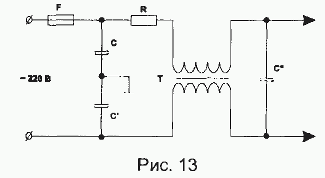
- short circuit power filter (see Fig. 13);
In this block, filter capacitors C, C1, C2 most often fail.
The current-limiting resistor R often burns out at the same time as the mains fuse F (if C, C1 are in good working order). The inductive filter T very rarely fails.
- network rectifier for bridge diode breakdown;
- a filtering capacitor after the diode bridge (it is large, with a capacity of 200-500 μF - for an operating voltage of 300-400V) for a short circuit;
- elements of the key modulator (pay special attention to the serviceability of the powerful terminal transistor of the PWM modulator, the elements of its framing, as well as the key microcircuit (if any)).
When you find a faulty element, analyze the reasons for its failure. In some cases, the failure of one or more elements is the result of a failure of a completely different unit.
For example, failure of a powerful key transistor of a power supply can be initiated by faults in protection circuits, output voltage tracking circuits, pulse transformer, PWM modulator.
After finding the faulty element and replacing it, repair the broken circuits.
In the event that the automatic power switching unit is faulty, the following may fail: a mains fuse, a current-limiting resistor R (see Fig. 13), a rectifier, filtering electrolytic capacitors, as well as elements of a PWM modulator. This is a rather serious malfunction. And the reason for all this is either the controller of the mains voltage switch, or a powerful transistor (thyristor).
2. The power supply does not turn on, the mains fuse is intact.
In this case, you should also check the elements of the path:
mains filter - rectifier - PWM - modulator.
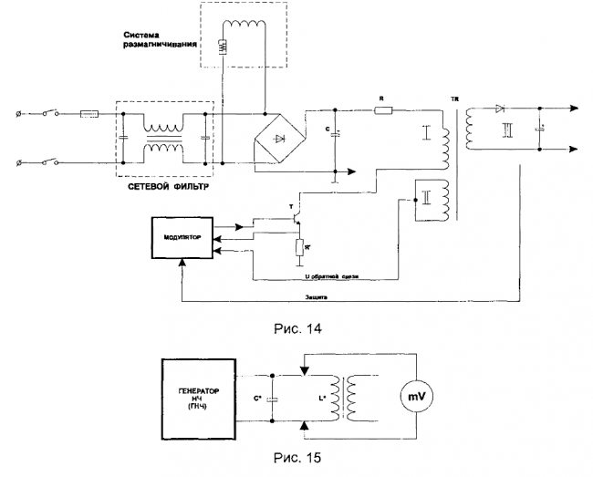
First, check if the mains electrolytic capacitor C has a constant voltage of about 300V (see fig. 14). If not, look for a break in the line filter, and also check the resistor R (Fig. 13).
If there is + 300V on the capacitor C, turn off the power, discharge C and check the circuit from the diode bridge through the primary winding of the pulse transformer to the collector (or drain - in the case of using a field-effect transistor) of the switch transistor T (Fig. 14)
You should also check the windings of the TP mains pulse transformer for short-circuiting of the turns.
The following method of testing pulse power transformers for short-circuited turns has proven itself well: the parallel resonance method (Fig. 15).
Necessary equipment:
- Low frequency generator (LFO).
- Oscilloscope or high-frequency millivoltmeter (with the ability to measure in the frequency range of 10 - 200 kHz).
Principle of operation.
The principle of operation is based on the phenomenon of resonance. An increase (from 2 times or more) in the amplitude of oscillations from the low-frequency generator indicates that the frequency of the external generator corresponds to the frequency of the internal oscillations C * L * of the circuit.
To check, short-circuit the secondary winding L of the transformer. The oscillations in the C * L * circuit should disappear. It follows from this that short-circuited loops break the resonance phenomena in the C * L * circuit. The presence of short-circuited turns in the L * coil will also lead to a breakdown of resonance phenomena. It should be noted that this test method is effective if the ratio of the number of short-circuited turns to the number of turns of the primary winding should correlate (under different conditions) as: Wsc / W> (1/100: 1/10) (see Fig. 16).
If you did not find a faulty element in the primary power circuit, check sequentially: semiconductor elements (transistors, diodes, optocouplers, etc.), then electrolytic capacitors and all other elements, if the power supply contains integrated microcircuits, they should be " check "replacement.
It should be noted that burnt, charred elements, as well as electrolytic capacitors with a swollen notch (on top of the case) are subject to immediate replacement.
Necessarily analyze the reason for the failure of the found faulty element.
You should also check (in some types of power supplies) the operation of the standby power supply, which, in turn, feeds the circuits that control the switching on of the main power supply (usually through optocouplers or special circuits).Since the standby unit has a low-power power transformer and a parametric stabilizer, the repair of this unit does not cause problems.
3. Power supply protection is activated
- check the elements of the output rectifiers of the power supply;
- check the power supply load for a short circuit;
- check the elements of the protection system (both the output voltage monitoring circuits and various protection circuits), see fig. 14:
- II feedback winding TR, modulator is a tracking circuit;
- T, R, modulator - current protection circuit of the output transistor T;
- the "protection" line, the modulator is actually the output voltage protection;
- check the feedback windings of the TR transformer (II see fig. 14);
- replace the key modulator microcircuit (if any).
4. "Floating" faults, that is, faults that appear periodically.
In this case, proceed as follows:
- check the elements for darkening on the case, etc .;
- check the conductive tracks on the circuit board so that there are no cracks or breaks on them;
- determine the places of the greatest local heating of the elements by blackening on the board and check the elements in this area.
In the event that a malfunction manifests itself during heating, the faulty element can be localized either by cooling (cotton wool moistened with acetone), or by provoking local heating of one or another element with a soldering iron. In any case, electrical safety measures should be followed.
5. Malfunctions not associated with defects in the power supply:
- the protection of the power supply is triggered, in this case, an overcurrent (short circuit) of one of the output power channels is possible - determine the overloaded channel, find the cause of the short circuit of the load;
- the power supply turns on for a short time, then turns off (only for power supplies with clocking from the unit by the scanning country) - in this case, you should check the feedback circuit from the line scan unit to the power supply;
- the power supply does not turn on from standby from the microcontroller - check the power-on control circuit from the microcontroller to the power supply.
Reed insulation can be used to insulate walls and partitions of sheds, chicken coops, livestock buildings, as well as floors of residential buildings with a relative humidity of no more than 70 percent. Craquelure (fr. craquelure) - the name of a special decorative effect that imitates the aged surface of a product. Craquelure - Cracks in a paint layer or varnish in a painting that form on oil canvases or ceramic dishes. Decorated "semi-antique", with the help of the craquelure effect, interior items and furniture can transform the look of the room where they are located: Unaware of the danger posed by a broken but energized wire lying on the ground, people sometimes approach it and even try to take it in their hand. At this moment, a person can instantly die from a step voltage or from a touch voltage. To prevent such accidents, scientists have developed original schemes of devices that make it possible to turn off the overhead line at the moment of a wire break, that is, even before it falls to the ground. More details ...
![]()
Video (click to play).

