In detail: do-it-yourself repair of the Lancer 9 clock spring from a real master for the site my.housecope.com.
I will help in tuning the clock spring (PE), it is also the steering column cable of the driver's airbag.
Symptoms: SRS malfunction icon illuminated on the panel.
write in a personal.
(except for multi-rudder)
I will accept a spoiled clock spring as a gift. who changed it to a new one, maybe it was lying around?
- Like
- I do not like
Will you turn off the light?
Here on the forum there is a manual on how to cure an hour's waste using spare tracks.
But not everyone has a spare. What will you do in this case? For me, for example, all 5 tracks are involved.
Is your steering wheel simple or multi?
you can not tell me where to find these topics, or throw links.
report on the repair of the clock spring PE (snail) for FAQ
Required tools
1.key asterisk 40.
2.Clean wrench with head 17.
3. Phillips screwdriver, long.
4. scalpel.
5.Soldering iron with a fine tip.
6. tester.
7. proofreader.
8. pin.
9. Pliers are thin.
Disassembly of the steering wheel.
We latch the steering wheel with the ignition key pulled out.
Unscrew the 2 fastening screws, on the sides, airbags (tool 1)
Remove the pad (from the bottom of the steering wheel) of the harness pads, you can pry it off with a scalpel or flat screwdriver
Disconnecting the signal pads (single)
and airbags (double)
Carefully remove the pillow and set it aside
Using the corrector, we fix the position of the steering wheel, applying two risks, one on the shaft, the other on the steering wheel.
Loosen the tightening of the steering wheel nut (tool 2)
With blows of hands, we knock down the steering wheel from the shaft splines and unscrew the nut to the end, remove the wheel.
Repair of the emergency mechanism (soldering the loop)
Before us is an emergency assembled (black bagel with a yellow sticker),
| Video (click to play). |
The gearbox is fixed with 2 screws; to remove it, it is necessary to disassemble the steering column cover.
We unscrew the 2 front casing screws, located on the bottom, this is enough to remove the emergency (tool 3)
Pry the joint between the upper and lower parts of the casing with a scalpel and carefully separate the halves.
We unscrew the 2-screws securing the emergency room itself, disconnect the signal harness pads and pillows on the steering column switch block and remove the emergency
It is better to remember the number of turns on the emergency mechanism, if suddenly the spring comes off during the repair. There are 6 turns in total, 3 to the left and 3 to the right + a small backlash. I also marked the position of the upper half of the PE relative to the casing.
The PE mechanism is collapsible.
In the donut hole there is a 3-snap fastener,
carefully release them with a scalpel. The bagel falls apart into 3 parts: upper with wires, lower with rollers and fastening
there is also the 4th but about it later.
We sit down more comfortably, arm ourselves with a tester and ring each track, my spring has opened up, I also visually examined it for breaks and scuffs. After ringing out, the breakage of the 3rd track was found, during visual inspection, rubbing in one place up to the metal.
Now the most important thing is to re-solder the contact to another track, for this it is necessary to disassemble the upper half of the PE, prying, from the sides, carefully with a scalpel the “box” with wires (4th part)
we disconnect it from the upper part of the state of emergency, take out the contact pad of the gearbox
On the checkpoint we see 2 free contacts. We tear off (it will not be possible to unsolder) the wire from the faulty track and solder it to any free one. We ring the train again. Lubricate the roller mechanism and the train with silicone grease. We turn over the contact on the harness block (which comes from the steering column switch block), you need a pin to disassemble the block. Everything.Putting it back together, check the SRS light is off, the goal is achieved.
Gender: husband
Mitsubishi Lancer IX 1.6
So, I bring to your attention a report on the replacement of a loop in an emergency!
I will not tell you how to take it off and disassemble it, because everything is well described HERE, it also describes how you can repair it, but as practice shows, this is not enough for long (it was enough for me for several weeks). I want to thank right away cappuccino for the faulty emergency provided for experiments.
Then we put everything in the reverse order, put it in place in the steering wheel, start it up and forget about this problem for a long, long time.
P.S. It may be more reliable to replace the loop completely, i.e. find it longer, but I did not find one, and I did everything to make this option as reliable as possible.
If anyone has any questions, write, I will definitely answer !!
Repair of the Mitsubishi Lancer 9 clock spring is a rather demanded service in our car service. Carrying out these and other works on Mitsubishi requires good qualifications from mechanics and often the use of special tools.
We strive to be fair and honest and treat our customers the way we would like to be treated with respect and consideration. For most of our work and spare parts, we give one of the longest guarantees in our city.
Without your consent, we do not carry out any additional repair work and do not increase the estimate. You will know in advance what work will be carried out with the car, how long it will take, what the total cost of work and spare parts will be.
You will be very surprised at the level of service when you visit our car service for the first time. Our employees DO NOT talk down to customers. We speak to you in a simple and understandable language without abstruse technical terms that make your head ache. After all, if you do not understand what we are talking about, then how can you make the right decision that your car needs?
All our services are certified in accordance with GOST-R, about which there are supporting documents. This means that you can service even a NEW car, just bought in the showroom, with the same quality, but at a fair price. At the same time, the manufacturer's warranty is fully preserved. For more details, see the section "Outside the dealer's service"
You have probably found yourself in a situation where you are told in a car service one time of issue, but in fact it turns out that it will be longer. Or even worse - when you come to the service to pick up the car at the appointed time, but it is not ready and you have to wait and change your plans. We carefully monitor this in our car service and with us you will not find yourself in a similar situation.
We never put pressure on clients to impose unnecessary work. For all questions that arise, we will always give you the necessary consultations and advise what needs to be done urgently and what you can wait with.
We use the latest diagnostic and repair equipment, which allows us to troubleshoot problems the first time. We have an extremely low percentage of repeated repairs. This means that you can be sure - if you come to us, you will leave only in a serviceable car.
We will be happy to accompany you to the workshop, if you wish to personally look at the detected faults. You will always know which specialist is responsible for your car and even which mechanic is doing the work.
We have a wide range of spare parts and consumables, both original and non-original. In the absence of the necessary parts in the warehouse, we will deliver them under the order as soon as possible, without intermediaries. This means that you do not need to look for something on your own, your car will not hang on the lift while waiting for spare parts and the repair will take place as quickly and conveniently as possible for you.
In yellow pants
Profile
Group: Users
Posts: 461
User #: 88072
Registration: 8.11.2011 - 12:59
MITSUBISHI
MR583930 Spring, airbag sensor cs3 24 (48) h RUB 4852 T. 280680
This post has been edited Keycar – 20.08.2012 – 17:40
In yellow pants
Profile
Group: Users
Posts: 461
User #: 88072
Registration: 8.11.2011 - 12:59
Download / Print topic
Download a theme in various formats, or view a printable version of the theme.
Yarportal rules
You are the owner of a well-equipped garage, where there is a full "ammunition" of tools for all occasions and planned repairs of the car, then you may think about how to change the rear pillars of the Lancer 9 yourself. Are you ready to spend 3-4 hours of your time replacing the front shock absorber struts, then get to work. The designated time will be needed directly for the repair work, if unforeseen situations do not surface. It is worth thinking about the allocation of time to find information on how to change the racks for the Lancer 9, when you should definitely resort to this. Secondly, we assess the financial capabilities, we determine from which manufacturers the spare parts will be purchased. And then there will be trips to the market, service centers, perhaps long waits for the necessary parts and kits for the depreciation system. Getting down to solving the question of how to change the rear pillars of the Lancer 9, figure out what kind of "beast" you will be dealing with.

When dismantling the rack, replacing its components, it is advisable to correctly understand what parts the product consists of. Let us recall the necessary information.
- Telescopic strut nut
- Upper support body
- Bearing located in the upper support
- Upper cup (support)
- Helical coil spring
- Lower spring cup (support)
- Telescopic stand
- Bump stop or damper.

When deciding how to change the racks for the Lancer 9, one thinks out right away whether to change only the rack or all the fastening systems, rubber gaskets, and the boot if it has been mechanically damaged. As usual, an individual approach is provided. It all depends on the age of the car, its technical condition, mileage, operating characteristics and the frequency of previous repairs.
It's no secret that the front struts on the Mitsubishi Lancer IX are regularly exposed to stress and wear. Firstly, the struts are located in the upper part of the support of the shock absorption system, therefore they take on the main "blows", feel all the imperfections of the road and incorrectness, inexperience in the process of driving. Secondly, the front pillar interacts with the car body and has points of contact. Also, during the maneuvering period, the strut "takes part" in providing turns and mitigating the load on the suspension from the occurring depreciation.
Experienced car enthusiasts know that if the Mitsubishi Lancer IX has a mileage of more than 100-150 thousand km, then it is worth thinking about how to change the rear pillars of the Lancer 9, and who to contact on this issue.
In addition, experienced drivers are accustomed to listening to the breathing of their vehicle. And when they hear the first symptoms, they tend to the service for a consultation. What can alert the driver?
- A subtle crackling sound at the front of the car when it enters a corner, especially a very sharp one.
- It seems that something is tapping at the bottom of the hood, especially in the area of the front wheels.
- There is a feeling that the steering wheel "feels" all the irregularities of the road, as if it shakes and reluctantly reacts to manipulations directed at it.
- By visually inspecting the front support under the hood, the driver can see the damage, resulting changes in the appearance of the damping system. Most often, wear is given out by the form of rubber gaskets, they seem to bulge out of the limits and seats allotted for them.
- From the look of a specialist or an experienced driver, you can determine a violation in the convergence of the front wheels, and this is already the clearest sign that you need to think about how to change the racks for Lancer 9, whether you have enough strength to do everything yourself.
- Poor maneuvering, "disobedience" of the machine is noticed with enviable constancy.In such a situation, the driver should not delay the repair of his vehicle, this is already fraught with danger on the road.
Thus, an experienced driver will not delay the decision of the question of how to change the rear pillars of the Lancer 9, realizing that this will lead to great damage and, perhaps, to a complete stop of the vehicle.
The set of tools is almost standard. And the more years Mitsubishi Lancer IX has been in operation, the more spare parts and keys appear in the garage of an experienced car owner. At the time of repair, they should only be found in the "bins" of the garage, systematized, if necessary, buy in addition, and calmly decide how to change the racks for Lancer 9. Let us recall the list of necessary items.
- Jack, the most common, as well as wheel chocks.
- Vise for working with a dismantled rack.
- Special keys for 12, 14, 17.
- Powerful spring locks to tighten the spring before dismantling.
- A hammer, a chisel, and wooden blocks for the stand and setting the supports.
- A set of new spare parts from the brand selected at will.
- Torque wrench. You may need it.
- WD special blend.

- Front shock absorbers from the Kayaba brand (Excel-G), serial number 334420. Factory fitted with the Mitsubishi Lancer IX shock absorbers 1.3 or 1.6. When replacing, it is possible to rotate and select a category - 2.0.
- The spare part Kayaba (Excel-G) 334369 is recognized as similar in quality as compared to the shock absorber of the 334420 series.
- In catalogs, support bearings under the code name - Mitsubishi MR272946 are most often chosen.
- If you need to replace the boot of the suspension spring, then choose the product Mitsubishi MR244220 or Mitsubishi MB303070 in the catalog.
- We recommend a shock absorber bumper for Mitsubishi Lancer IX if it is included in the catalog under Mitsubishi MR961189 code.
- We fix the machine in the working area, dismantle the front wheel when the jack is already working steadily.
- We disconnect the mountings of the ABS sensor and the brake hose, they have connections to the rack.
- We find in the hood the entrance to the "glass" of the front pillar, we untwist all the fasteners of the upper support.
- We carefully work with the fasteners at the bottom, if they do not give in, then we use WD grease and special keys.
- We take out the rack, while the axis is located on special struts.
- We clamp the old rack together with the spring in a vice and begin to “disassemble” it, first of all removing the spring clamped in the tie.
- We clean everything that is necessary, check, and replace the rack itself with a new one.
- Do not forget to pump the rack at least 5-10 times before installation.
- We assemble everything in the reverse order and attach it to the landing niches.
- It is recommended that the machine check the front wheels for toe-in.

Thus, the question of why and how to change the racks to Lancer 9 is consistently solved. Working on your own, you will have to tinker, because sometimes the mechanisms of the machine behave unpredictably during repair work. And if you know the simplest and most reliable method for replacing the Mitsubishi Lancer IX front strut, then share your experience.
We are waiting for your stories and comments on how you managed to replace a worn part.
The suspension system is a structural part of the vehicle's chassis that is responsible for softening and evenly absorbing stresses or vibrations that occur during vehicle operation. The suspension is the connecting element between the car body and the road surface.
The front end of the Lancer 9 is equipped with an independent Maxpherson lever-spring system, which is complemented by installed shock absorbers, anti-roll bars and coil springs. The main element in the design is the transverse shock-absorbing strut, the functional purpose of which is to ensure the operability of the telescopic guide element, as well as the damper, which is responsible for the distribution of loads about the vertical axis of the body.

ATTENTION! Found a completely simple way to reduce fuel consumption! Don't believe me? An auto mechanic with 15 years of experience also did not believe until he tried it. And now he saves 35,000 rubles a year on gasoline! Read more"
The functioning of the front suspension of the Mitsubishi Lancer 9 is due to the architectural features of the following structural elements:
- Shock-absorbing strut - the device consists of a compression buffer, a coiled shock-absorbing spring, and a protective casing with a pre-installed bearing, which transfer the load from the axles of the wheelbase to the car body. The strut connects to the ball joint knuckle, which connects the element to the suspension arm;
- Anti-roll bar - two metal brackets connect the part to the car body through shock-absorbing rubber pads. The suspension arms are combined with the vehicle body thanks to the fastening of silent blocks and rubberized bushings;
- Front wheel hub locations - installing the hubs on double-row angular contact ball bearings provides better distribution of loads on the body, which allows both to increase the operational life of the suspension and to increase the parameters of the maximum permissible axle loads.
The front suspension of the car is softer than the rear, due to the architecture of the structure. The difference in the functioning of the suspension systems makes it easier to drive, resulting in increased vehicle agility.
The rear suspension also has an independent structure, the architecture of which consists of multi-link telescopic struts and an anti-roll bar. The guiding elements of the rear suspension system are levers with different sized metal hinges, which increase the car's handling - when entering corners, the rear wheels rotate at a greater angle than the front ones, which creates the effect of passive steering.

The shock absorber strut dampens vibrations in the rear suspension, thereby relieving stress on the vehicle's hubs. The lower arms are structurally connected to the anti-roll bar, and the stabilizer struts are fixed through ball joints to the stabilizer bar. The bar is attached with rubber brackets and pads directly to the vehicle body.
The suspension system is an important structural unit, in the presence of malfunctions in which the operation of the vehicle becomes unsafe. The main symptoms of suspension problems are:
- Noise, rattling or extraneous noise in the suspension - possible damage to the shock absorber, wear of the silent blocks, or failure of the shock absorber or stabilizer springs. To fix it, it is necessary to replace the shock absorber strut, as well as install new gaskets and silent blocks;
- Retraction of the vehicle from the trajectory of movement - the reasons are violation of the camber angle or deformation of the trailing arms. The situation is corrected by calibrating the camber angles or by installing new parts;
Note! Violation of the vehicle's trajectory can also occur in the event of uneven pressure in the tires of the vehicle or the installation of rubber kits with a different type of tread.
- Uneven tire tread wear - possible overload or wheelbase imbalance. To eliminate the malfunction, it is required to regularly calibrate the wheels, as well as to prevent overloading the vehicle.
The diagnostic procedure is performed when the car is driven onto a lift or inspection pit. During the inspection, it is important that:
- Rubber parts and seals showed no signs of aging, wear or damage;
- Shock absorbers should not have smudges, chips or holes;
- The bearings were free of chips or rust;
- And the silent blocks had no mechanical damage.
Note! When checking for faults, you should also pay attention to the exhaust system.

Floor:
Age: 38
Driver
Is registered: 31.08.
Posts: 401
Location: Simferopol
Hello everyone!
I want to write a small photo report on replacing the clock spring.
First of all, I will unsubscribe that it is pleasant to deal with the author of the topic. Everything that the author said he did.
On Saturday I sent him a spring and made a money transfer.
On Monday, the clock spring arrived at a warehouse in Ternopil and the author promptly took it away and immediately sent me a repaired one.
A very big plus is that the author has an exchange fund and does not have to wait for him to repair it.
On Wednesday (today) I received it and have already delivered it.
As for the train itself, I did not find any differences from the original in appearance and touch.
Here is a photo for comparison.
What I want to draw the author's attention to is the presence of lubricant, or rather, in its complete absence.
Let me give you a little advice, lubricate the train when repairing, if this is not done, it will quickly fray again.
I lubricated it with such a silicone grease
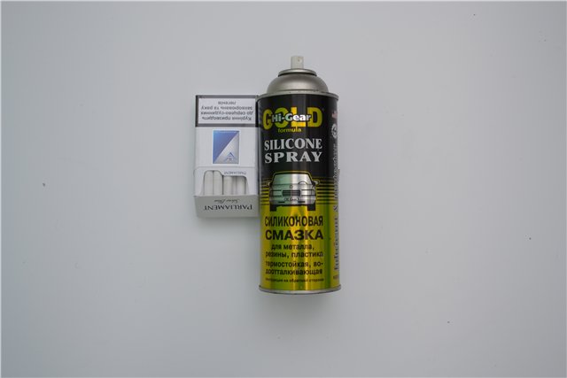
Now a small photo report on the replacement of the clock spring.
To replace, we need:
1. open-end wrench for 10 (for removing the battery terminal)
2.hexagon for 8 (for removing the steering wheel)
3. Shaped screwdriver (to remove the clock spring)
Let's start!
-Put the steering wheel and wheels exactly
-Remove the negative battery terminal
-Remove the cover on the right side of the steering wheel and disconnect the two contacts
-We mark the position of the steering wheel, I did it using ordinary electrical tape
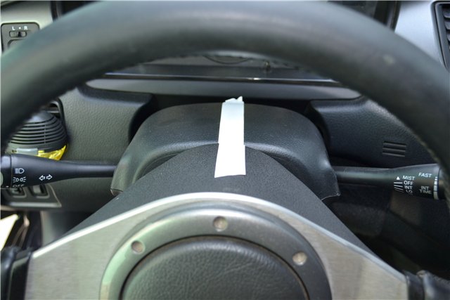

-Unscrew the bolt and pull the steering wheel towards us. I took off the steering wheel without much effort
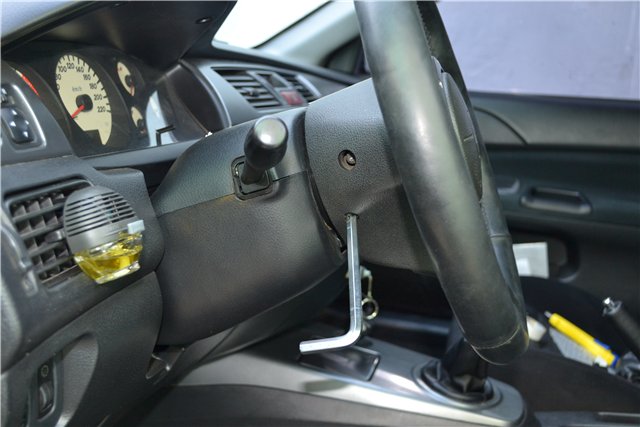

-Unscrew the three screws and remove the steering shaft cover
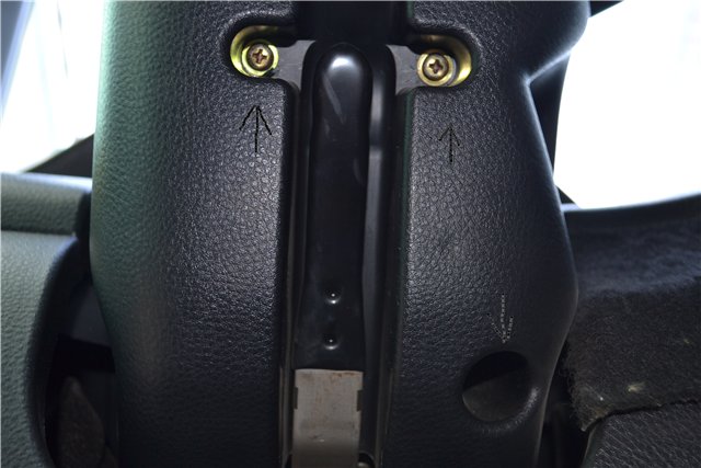

-Disconnect the two chips that are from the bottom
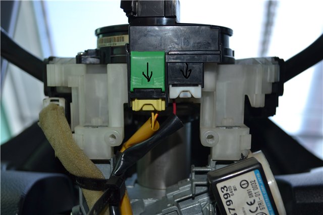

-Unscrew the two screws and, with a little effort, pull the spring towards you
Well, half the work is done, a smoke break and move on.
- Installing a new spring, here you should pay attention to the grooves. If they do not match, then the turn signals will not snap off when the steering wheel is returned.
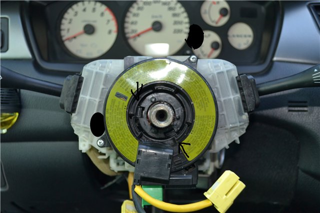
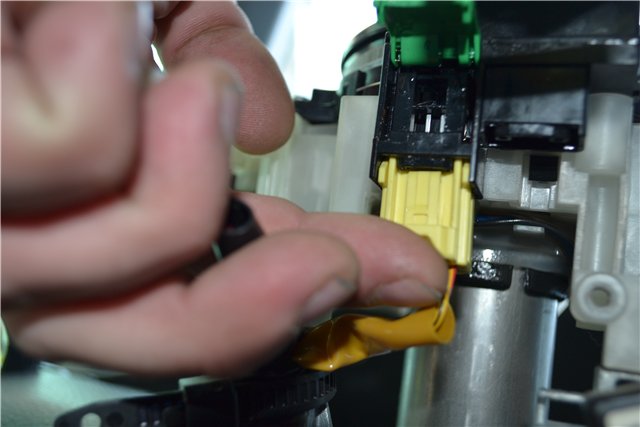
-Slip back to the bottom contacts

-And then, in the reverse order, we collect everything in place.
Hurray the SRS lamp went out
Well, something like this
_________________


Last edited by R-u-s-l-a-n (Wed Nov 30, 2011 8:59 pm); edited 3 times in total
Brand new trains (clock springs) Airbag-SRS MR583930
Train Airbag-SRS (clock spring) MR583930
Train-Time spring Airbag, SRS MR583930 fits the following models:
AIRTREK CU2W (CU #) 2000 03/2001 - 09/2005 JAPAN
AIRTREK CU4W (CU #) 2400 03/2001 - 09/2005 JAPAN
AIRTREK / OUTLANDER CU2W (CU2-5W) 2000 11/2001 -. ASIA AND SOUTH. AMERICA
AIRTREK / OUTLANDER CU4W (CU2-5W) 2400 11/2001 -. ASIA AND SOUTH. AMERICA
COLT / COLT PLUS,
Z21A (Z20 #) 1300 / 2WD (4A90) 10/2002 -. biennium, JAPAN
Z22A (Z20 #) 1300 / 4WD (4A90) 10/2002 -. yy, JAPAN
Z23A (Z20 #) 1500 / 2WD (4A91) 06/2003 -. years ASIA AND SOUTH. AMERICA
Z23A (Z20 #) 1500 / 2WD (4A91) 10/2002 -. biennium JAPAN
Z23W (Z20 #) 1500 / 2WD (4A91) [PLUS] 06/2003 -. ASIA AND SOUTH. AMERICA
Z23W (Z20 #) 1500 / 2WD (4A91) [PLUS] 10/2002 -. yy JAPAN
Z24A (Z20 #) 1500 / 4WD (4A91) 10/2002 -. biennium JAPAN
Z24W (Z20 #) 1500 / 4WD (4A91) [PLUS] 10/2002 -. yy JAPAN
Z25A (Z20 #) 1300 / 2WD (4G19) 06/2003 -. ASIA AND SOUTH. AMERICA
Z25A (Z20 #) 1300 / 2WD (4G19) 10/2002 -. JAPAN
Z26A (Z20 #) 1300 / 4WD (4G19) 10/2002 -. JAPAN
Z27A (Z20 #) 1500 / 2WD (4G15) 06/2003 -. ASIA AND SOUTH. AMERICA
Z27A (Z20 #) 1500 / 2WD (4G15) 10/2002 -. JAPAN
Z27AG (Z20 #) 1500 / 2WD (4G15) / WIDE 10/2002 -. JAPAN
Z27W (Z20 #) 1500 / 2WD (4G15) [PLUS] 06/2003 -. ASIA AND SOUTH. AMERICA
Z27W (Z20 #) 1500 / 2WD (4G15) [PLUS] 10/2002 -. JAPAN
Z27WG (Z20 #) 1500 / 2WD (4G15) / WIDE [PLUS] 10/2002 -. JAPAN
DION.
CR5W (CR #) 1800 05/2000 - 12/2005 ASIA AND SOUTH. AMERICA
CR5W (CR #) 1800 12/1999 - 12/2005 JAPAN
CR6W (CR #) 2000 05/2000 - 12/2005 ASIA AND SOUTH. AMERICA
CR6W (CR #) 2000 12/1999 - 12/2005 JAPAN
LANCER
CS1A (CS, CT #) 1300 (SEDAN) 09/2000 -. ASIA AND SOUTH. AMERICA
CS2A (CS, CT #) 1500 (SEDAN) 09/2000 -. ASIA AND SOUTH. AMERICA
CS3A (CS, CT #) 1600 (SEDAN) 06/2001 - 12/2006 USA
CS3A (CS, CT #) 1600 (SEDAN) 09/2000 -. ASIA AND SOUTH. AMERICA
CS3W (CS, CT #) 1600 (WAGON) 09/2000 -. ASIA AND SOUTH. AMERICA
CS6A (CS, CT #) 2000 / SOHC (SEDAN) 06/2001 -. USA
CS6A (CS, CT #) 2000 / SOHC (SEDAN) 06/2001 - 12/2006 USA
CS6A (CS, CT #) 2000 / SOHC (SEDAN) 08/2003 - 08/2007 ASIA AND SOUTH. AMERICA
CS6A (CS, CT #) 2000 / SOHC (SEDAN) 09/2000 -. ASIA AND SOUTH. AMERICA
CS6W (CS, CT #) 2000 / SOHC (WAGON) 09/2000 -. ASIA AND SOUTH. AMERICA
CS7A (CS, CT #) 2400 (SEDAN) 06/2001 -. USA
CS7A (CS, CT #) 2400 (SEDAN) 06/2001 - 12/2006 USA
CS7W (CS, CT #) 2400 (WAGON) 06/2001 -. USA
CS7W (CS, CT #) 2400 (WAGON) 06/2001 - 12/2006 USA
CS9A (CS, CT #) 2000 / DOHC (SEDAN) 09/2000 -. ASIA AND SOUTH. AMERICA
CT9A (CS, CT #) 2000TURBO / 4WD (SEDAN) [01M-] 06/2001 -. USA
CT9A (CS, CT #) 2000TURBO / 4WD (SEDAN) [01M-] 06/2001 - 12/2006 USA
CT9A (CS, CT #) 2000TURBO / 4WD (SEDAN) [01M-] 08/2003 - 08/2007 ASIA AND SOUTH. AMERICA
CT9A (CS, CT #) 2000TURBO / 4WD (SEDAN) [01M-] 09/2000 -. ASIA AND SOUTH. AMERICA
CT9A (CS, CT #) 2000TURBO / 4WD (SEDAN) [01M-] 10/2000 - 06/2007 ASIA AND SOUTH. AMERICA
LANCER CEDIA,
LANCER, LANCER CEDIA CS2A (CS, CT #) 1500 (SEDAN) 03/2000 -. JAPAN
LANCER, LANCER CEDIA CS2V (CS, CT #) 1500 (CARGO) 03/2000 -. JAPAN
LANCER, LANCER CEDIA CS2W (CS, CT #) 1500 (WAGON) 03/2000 -. JAPAN
LANCER, LANCER CEDIA CS5A (CS, CT #) 1800 (SEDAN) 03/2000 -. JAPAN
LANCER, LANCER CEDIA CS5AR (CS, CT #) 1800 (DRIVER'S SCHOOL) 03/2000 -. JAPAN
LANCER, LANCER CEDIA CS5AZ (CS, CT #) 1800 (DRIVER'S SCHOOL) [06M-] 03/2000 -. JAPAN
LANCER, LANCER CEDIA CS5W (CS, CT #) 1800 (WAGON) 03/2000 -. JAPAN
LANCER, LANCER CEDIA CS6A (CS, CT #) 2000 / SOHC (SEDAN) 03/2000 -. JAPAN e
LANCER, LANCER CEDIA CT9A (CS, CT #) 2000TURBO / 4WD (SEDAN) [01M-] 03/2000 -. JAPAN
LANCER / LANCER CLASSIC
CS1A (CS, CT #) 1300 (SEDAN) 12/2000 -. EUROPE
CS3A (CS, CT #) 1600 (SEDAN) 12/2000 -. EUROPE
CS3W (CS, CT #) 1600 (WAGON) 12/2000 -. EUROPE
CS9A (CS, CT #) 2000 / DOHC (SEDAN) 12/2000 -. EUROPE
CS9W (CS, CT #) 2000 / DOHC (WAGON) 12/2000 -. EUROPE
CT9A (CS, CT #) 2000TURBO / 4WD (SEDAN) [01M-] 12/2000 -. EUROPE
MINICAB, TOWN BOX, TOWN BOX WIDE
U61T (U60 #) 660 / 2WD (TRUCK) [99M-] 11/1998 -. JAPAN
U61TP (U60 #) 660 / 2WD (PANEL VAN) [99M-] 11/1998 -. JAPAN
U61V (U60 #) 660 / 2WD (VAN) [99M-] 11/1998 -. JAPAN
U61W (U60 #) 660 / 3CYL / 2WD (WAGON) [99M-] 11/1998 -. JAPAN
U62T (U60 #) 660 / 4WD (TRUCK) [99M-] 11/1998 -. JAPAN
U62TP (U60 #) 660 / 4WD (PANEL VAN) [99M-] 11/1998 -. JAPAN
U62V (U60 #) 660 / 3CYL / 4WD (VAN) [99M-] 11/1998 -. JAPAN
U62W (U60 #) 660 / 3CYL / 4WD (WAGON) [99M-] 11/1998 -. JAPAN
MONTERO
MONTERO V77W (V75,77W) 3800 / LONG WAGON [03M-] 02/2000 - 08/2006 USA
MONTERO V77W (V75,77W) 3800 / LONG WAGON [03M-] 02/2000 - 08/2006 USA
OUTLANDER
OUTLANDER CU2W (CU2,5W) 2000 02/2003 - 12/2008 EUROPE
OUTLANDER CU4W (CU4,5W) 2400 01/2003 -. ASIA AND SOUTH. AMERICA
PAJERO
V63W (V60,70 #) 3000 / SHORT WAGON [01M-] 02/2000 - 12/2006 ASIA AND SOUTH. AMERICA
V63W (V60,70 #) 3000 / SHORT WAGON [01M-] 06/1999 - 07/2006 JAPAN
V65W (V60,70 #) 3500 / SHORT WAGON [01M-] 02/2000 - 12/2006 ASIA AND SOUTH. AMERICA
V65W (V60,70 #) 3500 / SHORT WAGON [01M-] 06/1999 - 07/2006 JAPAN
V67W (V60,70 #) 3800 / SHORT WAGON [04M-] 02/2000 - 12/2006 ASIA AND SOUTH. AMERICA
V68W (V60,70 #) 3200D-TURBO / SHORT WAGON [01M-] 06/1999 - 07/2006 JAPAN
V73W (V60,70 #) 3000 / LONG WAGON [01M-] 02/2000 - 12/2006 ASIA AND SOUTH. AMERICA
V73W (V60,70 #) 3000 / LONG WAGON [01M-] 06/1999 - 07/2006 JAPAN
V73W (V73,77W) 3000 / LONG WAGON [01M-] 02/2000 - 06/2005 ASIA AND SOUTH. AMERICA
V75W (V60,70 #) 3500 / LONG WAGON [01M-] 02/2000 - 12/2006 ASIA AND SOUTH. AMERICA
V75W (V60,70 #) 3500 / LONG WAGON [01M-] 06/1999 - 07/2006 JAPAN
V76W (V60,70 #) 2800D-TURBO / LONG WAGON [01M-] 02/2000 - 12/2006 ASIA AND SOUTH. AMERICA
V77W (V60,70 #) 3800 / LONG WAGON [03M-] 02/2000 - 12/2006 ASIA AND SOUTH. AMERICA
V77W (V60,70 #) 3800 / LONG WAGON [03M-] 06/1999 - 07/2006 JAPAN
V77W (V73,77W) 3800 / LONG WAGON [03M-] 02/2000 - 06/2005 ASIA AND SOUTH. AMERICA
V78W (V60,70 #) 3200D-TURBO / LONG WAGON [01M-] 02/2000 - 12/2006 ASIA AND SOUTH. AMERICA
V78W (V60,70 #) 3200D-TURBO / LONG WAGON [01M-] 06/1999 - 07/2006 JAPAN
PAJERO IO
H76W (H60,70 #) 1800 / LONG (4WD) [99M-] 03/1998 - 06/2007 JAPAN
H77W (H60,70 #) 2000 / LONG (4WD) [01M-] 03/1998 - 06/2007 JAPAN
PAJERO / MONTERO
V64W (V60,70 #) 2500D-TURBO / SHORT WAGON [01M-] 02/2000 - 12/2006 EUROPE
V65W (V60,70 #) 3500 / SHORT WAGON [01M-] 02/2000 - 12/2006 EUROPE
V68W (V60,70 #) 3200D-TURBO / SHORT WAGON [01M-] 02/2000 - 12/2006 EUROPE
V73W (V60,70 #) 3000 / LONG WAGON [01M-] 02/2000 - 12/2006 EUROPE
V74W (V60,70 #) 2500D-TURBO / LONG WAGON [01M-] 02/2000 - 12/2006 EUROPE
V75W (V60,70 #) 3500 / LONG WAGON [01M-] 02/2000 - 12/2006 EUROPE
V78W (V60,70 #) 3200D-TURBO / LONG WAGON [01M-] 02/2000 - 12/2006 EUROPE
PAJERO / MONTERO IO
H67W (H60,70 #) 2000 / SHORT (4WD) [01M-] 11/1998 - 03/2005 ASIA AND SOUTH. AMERICA
H76W (H60,70 #) 1800 / LONG (4WD) [99M-] 11/1998 - 03/2005 ASIA AND SOUTH. AMERICA
H77W (H60,70 #) 2000 / LONG (4WD) [01M-] 11/1998 - 03/2005 ASIA AND SOUTH. AMERICA
PAJERO / MONTERO [LONG]
V73W (V70 #) 3000 / LONG WAGON [01M-] 02/2000 - 12/2006 ASIA AND SOUTH. AMERICA
V75W (V70 #) 3500 / LONG WAGON [01M-] 02/2000 - 12/2006 ASIA AND SOUTH. AMERICA
V76W (V70 #) 2800D-TURBO / LONG WAGON [01M-] 02/2000 - 12/2006 ASIA AND SOUTH. AMERICA
V77W (V70 #) 3800 / LONG WAGON [03M-] 02/2000 - 12/2006 ASIA AND SOUTH. AMERICA
V78W (V70 #) 3200D-TURBO / LONG WAGON [01M-] 02/2000 - 12/2006 ASIA AND SOUTH. AMERICA
PAJERO / MONTERO [SHORT]
V63W (V60 #) 3000 / SHORT WAGON [01M-] 02/2000 - 12/2006 ASIA AND SOUTH. AMERICA
V64W (V60 #) 2500D-TURBO / SHORT WAGON [01M-] 02/2000 - 12/2006 ASIA AND SOUTH. AMERICA
V65W (V60 #) 3500 / SHORT WAGON [01M-] 02/2000 - 12/2006 ASIA AND SOUTH. AMERICA P
V66W (V60 #) 2800D-TURBO / SHORT WAGON [01M-] 02/2000 - 12/2006 ASIA AND SOUTH. AMERICA
V67W (V60 #) 3800 / SHORT WAGON [04M-] 02/2000 - 12/2006 ASIA AND SOUTH. AMERICA
V68W (V60 #) 3200D-TURBO / SHORT WAGON [01M-] 02/2000 - 12/2006 ASIA AND SOUTH. AMERICA
Required tools 1. the key is an asterisk at 40.2. cylinder wrench with head 17.3. Phillips screwdriver, long 4. scalpel. Soldering iron with fine tip. 6. tester. 7. proofreader. 8. pin 9. Thin pliers. Dismantling the steering wheel. Snap the steering wheel with the ignition key pulled out. Unscrew the 2 fastening screws, on the sides, of the airbags (tool 1)
Remove the pad (from the bottom of the steering wheel) of the harness pads, you can pry it off with a scalpel or flat screwdriver
Disconnecting the signal pads (single)
and airbags (double)
Carefully remove the pillow and set it aside
Using the corrector, we fix the position of the steering wheel, applying two risks, one on the shaft, the other on the steering wheel.
Loosen the steering wheel nut (tool 2).
With blows of hands, we knock down the steering wheel from the shaft splines and unscrew the nut to the end, remove the wheel
Repair of the clock spring mechanism (soldering the loop) Before us is an emergency assembled (black bagel with a yellow sticker),
The clock spring is fixed with 2 screws; in order to remove it, it is necessary to disassemble the steering column cover.
We unscrew the 2 front screws of the casing, located on the bottom, this is enough to remove the emergency (tool 3) Use a scalpel to pry the junction of the upper and lower parts of the casing and carefully separate the halves. on the block of steering column switches and remove the emergency.
It is better to remember the number of turns on the emergency mechanism, if suddenly the spring comes off during the repair. There are 6 turns in total, 3 to the left and 3 to the right + a small backlash. I also marked the position of the upper half of the emergency room relative to the casing. The emergency mechanism is collapsible. In the donut hole there is a 3-snap fastening
carefully release them with a scalpel. The bagel falls apart into 3 parts: upper with wires, lower with rollers and fastening
There is also a 4th one, but more about it later. Let's sit comfortably, arm ourselves with a tester and call each track, my spring has opened up, I also visually examined it for breaks and scuffs. After ringing out, the breakage of the 3rd track was found, during visual inspection, rubbing in one place up to the metal. Now the most important thing is to re-solder the contact to another track, for this it is necessary to disassemble the upper half of the PE, prying, from the sides, carefully with a scalpel the “box” with wires (4th part)
we disconnect it from the upper part of the state of emergency, take out the contact pad of the gearbox
| Video (click to play). |
On the checkpoint we see 2 free contacts. We tear off (it will not be possible to unsolder) the wire from the faulty track and solder it to any free one. We ring the train again. Lubricate the roller mechanism and the train with silicone grease. We turn over the contact on the harness block (which comes from the steering column switch block), you need a pin to disassemble the block. Everything. Putting it back together, check the SRS light is off, the goal is achieved.

