In detail: do-it-yourself repair d 21 from a real master for the site my.housecope.com.
ASSEMBLY OF THE ENGINE D-21 OF THE TRACTOR T-25
ASSEMBLY OF THE MAIN UNITS OF THE D-21 ENGINE OF THE T-25 TRACTOR
Before the general assembly of the engine, the following assemblies must be assembled: crankcase, timing gear cover, piston with connecting rod and rings, crankshaft, balancer shaft, cylinder heads, oil pump, engine lubrication system pressure relief valve, fan belt tensioner, fan with generator , air cleaner, coarse and fine fuel filters.
The assembled engine, before being installed on the tractor, is run in at the stand and tested.
Assembling the block crankcase of the D-21 engine of the T-25 tractor
Before assembly, blow out the oil channels of the crankcase with compressed air through the holes in the camshaft bushings. After purging, press two pins into the front wall of the crankcase block to install the front sheet, ensuring that the pins protrude above the plane by 30 ± 0.5 mm. Press in the pin of the idler gear, aligning the holes in the flange of the pin and in the crankcase. Screw in two BNP-M8 x20 bolts with lock washers. Tighten and secure the screws. When pressing in the pin of the balance gear idler, an angle of 45 ° must be maintained between the pin holes and the crankshaft relative to the horizontal.
After that, flush the channels of the crankcase with a 1% solution of soda ash, heated to 70-80 °, and blow out the oil channels with compressed air.
Screw 1/8 ″ sealed tapered plugs in the paint into the tapped holes on the top surface of the crankcase and on the left wall on the corner surface. Protrusion of plugs above the plane is not allowed.
| Video (click to play). |
On the left side of the block in the front, screw in two sealed tapered plugs on the paint: 1/4 ″ at the top and 1/8 ″ at the bottom. Screw in a 1/4 "sealed conical plug on the front wall of the crankcase in the upper left corner and 1/8" on the lower plane in the front left corner. The protrusion of these plugs above the planes is also not allowed.
Press two pins into the holes on the rear wall of the crankcase for the flywheel housing, ensuring that the pins protrude above the plane of 16 ± 0.5 mm.
Screw the eight flywheel housing fastening pins into the rear wall of the crankcase until they stop in the thread runout.
The T-25A tractor is an excellent choice for your farm. It will greatly simplify the already difficult work in the field.
The T-25 tractor is a wheeled vehicle designed for plowing light soils, light-duty work and use with a mower and other non-self-propelled equipment. It is equipped with rear wheel drive and small front drive wheels. T-25 was assigned a traction class of 0.6.
In 1966, the first T-25 models rolled off the assembly line of the Kharkov tractor plant. In the 72nd year, production was transferred to the Vladimir Tractor Plant. A year later, the T-25 was removed from the assembly line, replacing it with an upgraded version of the T-25A, which is still being produced by the plant today. This model has found wide application in the national economy of the Soviet Union, and now in Russia.
The prototype was the DT-20 tractor, almost completely redesigned by the developers at the Volgograd Tractor Plant. The result is a multifunctional machine for the national economy at an affordable price. Over the entire history of production, more than 800 thousand units have rolled off the assembly line. Due to its small size, the tractor was widely used in the communal sector, together with trailed equipment. For the repair of the T-25 tractor, they continue to use the books of past years.
The version of the T-25A tractor is considered the base model for subsequent changes. On its basis, the T-25A3 with a safety frame and the tilt T-25A2 were developed.These were all the fundamental differences that should be taken into account when repairing the T-25 tractor. Rear-wheel drive and traction class remain the same. The T-30A80 model has undergone significant changes. She became all-wheel drive with a comfortable cab, equipped with a new D-120 power unit and power steering.
- The first models used the D21A1 engine with a rated power of 20 hp. The modified T-25A received a 25 hp unit. It is an air-cooled, four-stroke diesel engine with an autonomous thermal regulation lubrication system. An electric starter is used to start.
- The T-25 has a mechanical eight-speed transmission (with two low forward gears), a pendulum hitch and a rear hitch system.
- The weight of the tractor with an empty tank and without taking into account the load was 1.78 tons.
- Linear parameters: length - 3.11 m, width - 1.37 m, height - 2.5 m.The track width range varies from 1.2 m to 1.4 m.
- The specific consumption of diesel fuel at a crankshaft speed of 1800 rpm does not exceed 190 g / hp h.
A significant nuance of the T-25 model range was the presence of a cab heating system powered by the machine's hydraulics. The modernization of the 96th year also affected the heating, which became tied to the lubrication system of the power unit. On all T-25s, the hydraulic system is divided into aggregate units and is equipped with an independent drive part of the hydraulic pump.
The revolutionary solution of those years was the use of a semi-frame base of the tractor, which made it possible to change the track width and agrotechnical clearance. Another feature is considered when repairing a T-25 tractor, setting up work in reverse gears for a long time.
The basis of the multifunctionality of tractors of this type is a large number of non-self-propelled trailed equipment designed for them. The T-25 tractor today is the most affordable technique with a closed cabin.
The cost on the secondary market varies in the range of 50 - 450 thousand rubles. The price of a new one starts at half a million rubles. The T30-69 tractor, widely used in agriculture, and low-power devices from Chinese manufacturers (FT-254, Fengshou FS 240) are considered analogues of the T-25. They all have similar characteristics and are in the same price range.
Tractor T-25 (repair of the T-25 tractor)
The book contains the device and the operating procedure, recommendations for the repair of the T-25 tractor. The issues of car care are covered in detail, recommendations for the most correct use of the tractor in all works are given.
The book is intended for machine operators working on tractors.
Attention, on October 20 (Saturday) from 9.00 to 10-00 Moscow time, the portal will be unavailable due to technical work
You can ask questions only after registration. Login or register, please.
What we have is a homemade product with a D21 engine. After purchase - breather, oil change - approx. It still smokes blue in the exhaust.
Spring video
The pressure on the cold one is 3, on the hot one I don’t remember. Hawking butter aki elephant brooms.
It is hard to start, it takes a long time to oil without a decompressor.
I gave the fuel for repair - pump capital (beam), nozzle adjustment (new).
In the meantime, I opened the heads. The piston in the casings is like the leg of the 38th in the boot of the 42nd dangles.
I bought a set from Kostroma.
Went through.
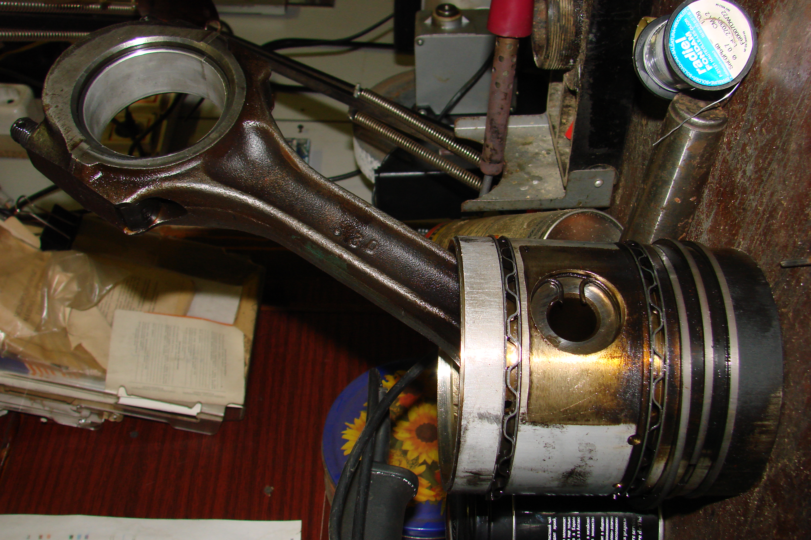

Replaced the connecting rod bushings.

In general, I collected everything in a heap. Starts up with half a turn.
The first cylinder smokes again: bang :.
Pressure 3. The cylinder head heads are different. The first (native) - VMTZ D144. On the second I found only three letters
 ZMZ.
ZMZ. The locomotive departs:
Tell me where to look - what to change. My opinion is that oil pours through the valve guides, BUT the valves are dry on the back side, only covered with soot and inlet and outlet.
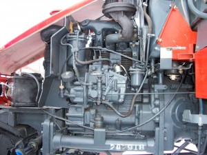
On the left side (Fig. 35), in the direction of the T-25 tractor, the diesel engine contains: fuel equipment, inlet and outlet pipes, a spark suppressor, an oil filler neck, a middle deflector (guide plate) and a suction air heating plug.
On the right side (Fig. 36) there is a decompressor drive mechanism, a starting starter, injectors and an easily removable fan casing, an oil pan drain plug, a pressure reducing valve, and a fan casing.
At the front of the engine (fig. 37). there is an axial fan with a built-in generator, the guide vane of which is fixed to the engine with a band clamp, a motor-hour meter, a full-flow jet centrifuge (oil filter), a dipstick, a fan and generator drive pulley with marks "ВМТ", "НМТ" and "Т »For setting the piston of the first cylinder at top dead center and setting the angle of the beginning of the fuel supply by the pump.
On the rear side of the engine of the T-25 tractor, directly to the crankcase, a flywheel cover is attached (Fig. 38 and 39).
On the upper plane of the crankcase there are ribbed cylinders with aluminum alloy heads. With their machined surfaces, the cylinders are inserted into the openings of the crankcase and are attached to it together with the heads with anchor pins screwed into the upper plane of the crankcase.
Rice. 35. Engine D-21 (left side view):
1 - motorcycle hours counter; 2 - centrifuge; 3 - fuel filters; 4 - outlet pipeline; 5 - spark arrestor muffler; 6 - fuel pump; 7 - flywheel; P - air heating candle; DM - oil temperature gauge sensor.
Rice. 36. D-21 engine (right side view):
1 - engine crankcase; 2 - starter; 3 - fan casing; 4 - fan clamp; 5 - pressure reducing valve; 6 - oil pan.
Rice. 37. D-21 engine (front view):
1 - fan; 2 - fuel filter; 3 - air heating candle; 4 - centrifuge; 5 - dipstick-oil meter; 6 - drain plug.
Rice. 38. D-21 engine (longitudinal section):
1 - oil pump; 2 - connecting rod; 3 - piston; 4 - fan; 5 - cylinder head; 6 - valve; 7 - crankcase; 8 - flywheel.
Rice. 39. D-21 engine (cross section):
1 - oil receiver; 2 - starter; 3 - fan casing; 4 - inlet pipeline; 5 - air heating candle; 6 - outlet pipeline; 7 - cylinder; 8 - crankcase; 9 - roller of the balancing mechanism; 10 - drain plug.
A copper gasket is installed between the crankcase and each cylinder to seal.
There is a cylindrical groove on the lower plane of the head, which serves to seat the head on the machined surface of the cylinder. The required seal between the head and the cylinder is achieved by pressing the upper plane of the cylinder, which has two annular recesses of a semicircular section, into the lower plane of the head. Parts of the valve and distribution mechanism are installed on the heads.
From above, the valve covers, cast from an aluminum alloy, are attached to the heads with studs.
An oil pan is bolted to the bottom of the crankcase. The oil pump receiver strainer is mounted in the pallet.
Crankshaft of the T-25 tractor
On the SSh T-16 M and T-16 MG installed D-21A engine four-stroke, two-cylinder air-cooled, direct fuel injection.
On the right side of the engine there are: fuel pump 2 (fig. 7). fuel filters 7, inlet 3 and outlet 6 pipelines, spark plug 4 for heating intake air, dipstick 9 and middle deflector. On the left side there are: decompression mechanism, starter 14, generator 12, injectors 20 and an easily removable fan casing 16.
Rice. 7. D-21A engine (a - left side view, b - right side view, in section):
1 - operating hours counter; 2 - high pressure fuel pump; 3 and 6 - intake and exhaust manifolds; 4 - glow plug; 5 - muffler; 7 - fuel filters; 8 - plug of the oil filler neck; 9 - dipstick-oil meter; 10 - drain plug; 11 - oil pan; 12 - generator; 13 - crankcase; 14 - starter; 15 - fan fastening clamp; 16 - directing fan casing; 17 - centrifuge; 18 - fan; 19 - TDC indicator; 20 - nozzle; 21 - valve; 22 - cylinder column; 23 - cylinder; 24 - piston; 25 - connecting rod; 26 - crankshaft; 27 - roller of the balancing mechanism; 28 - intermediate gear.
In front of engine D-21A there are: oil filler neck 8, centrifugal oil filter 7, fan 18, hour meter 1, pulley leading drive fan 18 and generator 12 with marks ВМТ, НМТ, Т1 and Т2 for setting the fuel injection advance angle and valve adjustment. The flywheel and flywheel housing are located at the rear.
In the upper part there are cylinders 23 which are attached together with the heads 22 to the crankcase 13 of the engine by means of anchor pins.
Inside the crankcase of the D-21A diesel engine are located: crankshaft 26 and camshafts, valve pushers and shaft 27 of the balancing mechanism. Between the front sheet and the aluminum cover, the distribution gears of the drive of auxiliary mechanisms and an oil pump are mounted.
In the lower part, the engine sump is reinforced, inside which the oil intake is located.
Details of the frame of the D-21A diesel engine are shown in Fig. eight.
Rice. 8. Details of the frame of the D-21A diesel engine:
1 - cover of distribution gears; 2, 8, 35, 43 - pin; 3 - insert; 4 - TDC indicator; 5, 22, 30, 45, 55 - gasket; 6, 26, 27, 58 - locking plate; 7 - front sheet; 9, 48, 50, 52, 62, 63, 64, 66, 67, 68 - bolt; 10, 32, 49, 51, 59 - washer; 11, 54 - finger; 12, 19, 42 - conical plug; 13 - anchor hairpin; 14,17,18, 21, 36, 53 - sleeve; 15 - cylinder; 16 - cylinder gasket; 20 - diesel engine crankcase; 23, 37, 40 - hairpin; 24 - eye bolt; 29 - flywheel housing; 41 - nut; 31 - seal housing; 34, 56 - frame seal; 38, 44 - bearing cover; 46 - sealing square; 61 - seal; 65 - screw.
D-21 engine (D-120 engine) - two-cylinder, four-stroke engine with direct fuel injection and air cooling.
This model is designed for installation on tractors (for example, T-25 and T-30), self-propelled chassis (T-16) of the 0.6 ton class, small-sized loaders, welding units such as ADD, power plants, compressor stations, etc.
We offer new and refurbished diesel engines D-21 (D-120)... Here you can to renovate your motor, buy a new or remanufactured diesel engine D-21 (D-120).
The D-21 engine, well known for several decades (since 1967), has established itself as a reliable, economical, easy to operate and maintain diesel engine. Today D-21 is produced under the brand name D-120.
Moreover, compared with the original model (D-21) D-120 engine it has a higher crankshaft speed and increased power.
The main advantages and characteristics of the D-120 / D-21 diesel engine are:
- Availability air cooling systems engine, which simplifies its installation, maintenance and operation (there is no need to install a radiator, expansion tank and other elements necessary for a liquid cooling system). In addition, the air cooling system allows the use of diesel engines D-120 and D-21 in all climatic zones with a temperature range from plus 40 degrees to minus 40 degrees;
- installed in the D-120 / D-21 engine original balancing mechanism, eliminating vibration, which is inherent in two-cylinder engines;
– compact overall dimensions, relatively low weight (technical characteristics of the D-120 engine are given in the table below);
– specific fuel consumption is at the level of the best examples of the world engine building;
-optimal layout on equipment and ease of maintenance.
Depending on its applicability and purpose, the D-120 diesel engine is produced in configurations with a nominal crankshaft speed of 2000 rpm, 1800 rpm and 1500 rpm.
Hello, Yuri, help me figure it out. Vystovil injection as shown. On t, he turns a minute for a minute, then white smoke appears from the exhaust pipe and does not start. What to do. I also had it before. Twist it for a minute and then it starts. What else could be the problem.
Juura told as a replacement for maces parasites and shtirioky
Please tell me what is the working compression on t engine d
Yuri hello, I have a goby, the engine does not spin more revolutions, they said to set the injection timing, how to do it correctly?
My friend, tell me if you can. On the weekend I tried to adjust the injection timing, I did everything as you showed, fixed the first cylinder at the top point, inserted a bolt into the flywheel, everything coincided. Then he unscrewed the fuel pump cover, loosened three nuts, began to turn the central shaft and not in any, there is a gear, as I understand it, and not here or there, well, it moves just a little bit, although this also affects the start-up. Engine d euro pump motorpal, took in December. I'm just suffering in minus in general, it drives for a long time to start.
At least like how I started it! The first time I saw this, but in general, I clearly explained everything and showed
Hi Yuri. Today I could not start it. He put the ignition on with a lamp. It didn't work. What could be
Hello, Yuri, after a small repair, it was necessary to set the injection moment watched your video did as you said started the engine, everything works, but on the second day I turn the engine with a starter for a minute and only then it starts, you know what the problem is
And on the t before the VMT there are two risks. Yak vistaviti there?
Hello! And approximately once in what time it is necessary to make one such prophylaxis to the engine, mine has worked for years and does not give any signs.
You limp on your right leg! The outsole is thinner!
Sorry for the right sap! And so all the rules!
Yura clarify, it is clear to me that it is necessary to set the top dead center of the piston of the first cylinder and use the wrench where the multi-hole washer is installed to wind the fuel supply
Yuri such pipes are on the tractor t
Good day, Yuri, give me advice on where to find the high-pressure pipes on which the compressor is installed.
Hemp zaviv! It’s good, if something is rocky without a starter.
Hi Yura replaced the nozzles and so one is flowing Shaiba changed new ones. Pulling a pipe, what could it be?
We invite you to the tractor group t http ok. Ru malayaspet. We communicate, share our experience. We invite friends.
Those who do not understand the first time will not understand, and the second in our village call this multi-hole child
This video is good. If I hadn't done it earlier on the advice of a matchmaker, I would have done as you tell and like
On the T 25 tractor, the engine is 4-stroke, diesel, air-cooled. Its name is D 21. It has two cylinders, which are arranged in series and vertically. It is a modification of the D-37M 4-cylinder power unit and began production at the Vladimir Tractor Plant back in 1967.
It is started by electric starters and has direct fuel injection. Vibration is inherent in two-cylinder engines. However, the designers used a specially designed balancing mechanism here. Its design is simple and efficient. This is a cushion and 2 counterweights. The roller rotates at the same speed as the crankshaft, but in the opposite direction. And counterweights, located on the pulley, additionally help to reduce vibration to acceptable levels.
The D 21 engine mounted on a tractor has the following main technical characteristics. The cylinders operate in a 2-1-0-0 pattern. Volume 2.1 liters. Power 20 HP or at 1600 rpm. Compression ratio 16. Fuel consumption 195 g / ehp. Oil volume 7 liters. Weight 280 kg.
Subsequently, somewhat different engines were installed on the T 25. One letter A and the number 1 were added to D21. The engine became known as D 21A1. However, the main difference lies elsewhere. This engine has become more powerful by 5 hp, that is, its power has increased to 25 hp or 18.4 kW, if measured slightly differently. But the essence does not change from this. The number of revolutions reached 1800. The compression ratio became 16.5. Due to these increases, the engine became more high-torque and the T 25 tractor was more powerful.
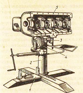
General assembly order. To assemble engines on a production line under the conditions of specialized repair enterprises, racks-racks or conveyors are used, which make it easy to install them in a convenient position for assembly. For individual assembly of engines, the universal stand OPR-989 is used [Fig. 26] and others.
Rice. 26. Universal stand OPR-989 for disassembling and assembling the engine.
1) - Base; 2) - Pipe; 3) - Shaft of rotation; 4) - Worm gear; 5) - Cylinder block.
WITHstart assembling the cylinder block: you need to install bushings and a camshaft, pusher bushings and pushers, oil seals and decompressor rollers, oil pipes. Then you should once again blow through the oil passages in the block with compressed air and install the idler pin, pins and other parts.
V the block is laid with a crankshaft with main bearings, then the cylinder liners, a connecting rod-piston set, a rear beam and a flywheel, an oil pump and a crankcase, a cylinder head, a turbocharger and a rocker mechanism, fuel equipment, filters and pipelines, intake and exhaust manifolds, a water pump are installed and fan, gearbox, starting motor and clutch in a sequence that depends on the design of the engine.
Installing the crankshaft. It is recommended to first assemble and tighten the main bearings without a shaft. The tightening torque of the nuts for YaMZ-238NB engines is 422-460 Nm for the main bolts; adjacent 98-118 N.m .; A-01 and A-41 - 410-440; type SMD - 200-220 N.m (bolts SMD-60 - 160-180 N.m); D-37M - 140-160 N.m; ZMZ-53A - 110-120 N.m; ZIL-130 - 110-130 N.m for the front and 80-100 N.m. for the rest of the bearings. Measurements determine their ovality, taper, oil gap and displacement of the upper insert relative to the lower one. In order to ensure an 80% resource, during overhaul, the clearances in the main bearings are not more than: 0.156 mm - SMD-60, 0.160 mm - A01M; 0.180 mm - A-41; 0.120 mm - D-37M; 0.08 mm - ZMZ-53A; 0.065 mm - ZIL-130; 0.130 mm - YaMZ-238NB.
TOLubricate the shaft journals with a thin layer of oil, install the spacer half rings, then lay the crankshaft. First, the middle main bearing is evenly tightened in two or three steps. If the shaft turns easily by the bolt in the flange, then the remaining bearing caps are tightened evenly. If the shaft turns tight, then it should be removed and the necks should be lubricated with a thin layer of paint. Then you need to re-lay the shaft, turn it, disassemble, inspect - by the ink prints on the liners, determine the cause of the tight turning and eliminate it.
PMoving the crankshaft along the axis, check the axial take-off run with a dipstick, which for diesel engines ranges from 0.1-0.4 mm, for automobile engines 0.08-0.25 mm. The axial take-off is regulated by the selection of the thickness of the spacer half rings, the thickness of the shoulder of the mounting bearing, or other devices for engines of this type.
PCorrectly laid shaft should turn from the force of the hand applied to the connecting rod journals.
Installing sleeves in the block. The sleeves, which are installed in the block, must be of the same size group, new or of the same repair size, and in the block without O-rings must be free to rotate.
PAfter installing the O-rings, the sleeves should be pressed into the block using a tool with a hydraulic (pneumatic) press or a wooden block and a hammer. It is not allowed to cut the O-ring when pressing.
PAfter pressing-in, the sleeve should protrude 0.10-0.21 mm above the plane of the block for diesel engines SMD-17, SMD-18; 0.09-0.15 mm for D-240, D-241; 0.07-0.27 mm for D-160; 0.65-0.165 mm for diesel engines of other brands. The difference in the protrusion of the sleeves for one block is not more than 0.05 mm. The protrusion allowed without repair is 0.04 mm (for A-01M and A-41 diesel engines, the protrusion is 0.05 mm).
PWith a pressed-in and fixed head, the ovality and taper of the sleeves on the working area are checked from the side of the crankcase (no more than 0.03 mm is allowed).
PWhen carrying out routine repairs, the sleeves must be installed in the block, turning around the axis by 90 degrees relative to the previous position, in order to increase the subsequent service life due to a decrease in ovality.
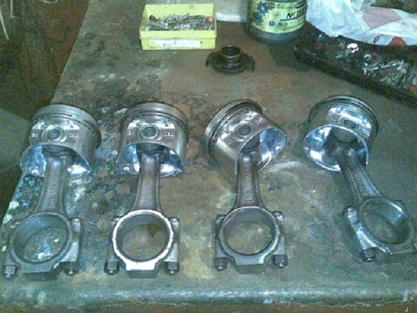
Installing the connecting rod and piston kit. The kit and the inner surface of the liner must be lubricated with diesel oil before installation.The locks of the first and second piston rings are located at an angle of 180 degrees relative to each other on the pistons of YaMZ-238NB, SMD-18 diesel engines, and between the second and third - at an angle of 90 degrees. On the pistons of ZMZ-53, SMD-60, A-01M and other engines, the locks are positioned at an angle of 120 degrees to one another. In this case, the locks should not be placed against the axis of the finger.
ShThe atunno-piston set is installed into the block from the side of the cylinder head using a ring compression device. In this case, you should pay special attention to the correctness of its location relative to the block (combustion chamber, slots in the piston skirt, arrows on the piston crown, etc.).
BBolts or nuts of connecting rod bearings are tightened with a torque wrench, maintaining a torque of 240-260 Nm. for diesel engines SMD-60; 196-216 N.m. for YaMZ-238NB, YaMZ-240B; 170-190 N.m. for A-01M, A-41; 140-160 N.m. for D-50, SMD-17, SMD-18 and others; 100-120 N.m. for D-37M, D-144, D-21; 68-76 N.m. for carburetor engines ZMZ-53N; 70-80 N.m. for ZIL-130. In ZMZ-53 engines, when assembling the lower connecting rod head, the protrusion on the cover and the number on the connecting rod must match.
PAfter installing the connecting rods, the crankshaft turning moment should not exceed 50 Nm.
Dthe bottom of the pistons after installing the connecting rod-piston set in position b. m. t. should protrude or sink relative to the plane of the block by the size shown in table 52.
Table 52. The location of the piston crown in relation to the density of the block.
First of all, for a high-quality overhaul of the engine, an experienced and knowledgeable mechanic is needed. After all, overhaul, unlike current repairs, requires much more knowledge and skills.
The most common reason for this costly operation is severe engine wear. As a rule, this happens after a long run or due to improper operation, usually an untimely oil change or a violation of the temperature regime. But there may be other reasons when an engine capital is needed. The so-called water hammer, when an abruptly large amount of liquid enters the air intake system or mechanical damage as a result of an accident.
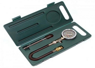
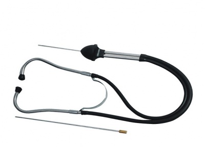
In the process of checking the condition of the motor, a special device is used - a compression meter. Also, a professional mechanic uses a special model of a stethoscope. The compressor is inserted into the plug hole, the ignition module is turned off and the starter makes several revolutions on each cylinder until the maximum value is obtained. The normal value is from 8.5 MPa.
Overhaul of the engine affects almost all engine components. Here is a list of engine overhaul parts:
- repair half rings;
- 7 large and 5 small. clamps;
- set of spark plugs;
- vacuum hose;
- main and connecting rod bearings p 1 set;
- a set of pistons and fingers;
- set of rings;
- a complete set of valves;
- valve guide kit;
- valve seals (valve stem seals) for all valves;
- engine oil seals 3 pieces;
- gaskets 3 pcs. (block head, pallet and valve cover);
- oil filter;
- 6 liters of mineral oil for the engine (m6);
- gear oil for the check point (4 l.);
- for valve cover 2 rubber grommets;
- set of block head bolts;
- a complete set of paper spacers;
- oil pump with intake;
- 10 liters of antifreeze;
- air filter;
- timing belt;
- generator belt;
- breather pipe;
- special clamp for the muffler.
The list of spare parts is quite long, but it directly depends on the amount of future work. At the cost of spare parts, you can never say something unequivocally. It all depends on the manufacturer, and on the shopping center or auto shop.
This amount of work on the overhaul of the engine requires so many spare parts:
- removing the engine;
- engine wash;
- disassembly of the engine;
- flaw detection of engine parts;
- repair of the cylinder head;
- boring and honing of the cylinder block;
- replacement of oil pump drive shaft liners;
- crankshaft grinding;
- crankshaft polishing;
- removing and installing plugs, cleaning the crankshaft channels;
- replacement of the input shaft bearing;
- grinding the surface for the crankshaft oil seal;
- repressing of pistons;
- engine assembly;
- engine installation.
All this also requires a huge number of tools. The mechanic locksmith uses almost all of his arsenal. Not only a standard set of wrenches, but also special tools, pullers, grippers, drifts and other tricks.
A separate item is engine running-in after overhaul. This is a separate and very important process worthy of special consideration.
How much an engine overhaul costs depends, as already mentioned, on many factors. This is the region where the work will be carried out, and the cost of parts, and the contractual potential of the car owner. But in general, you can focus on the figure of 20-30,000 rubles for a 16-valve VAZ engine.
You need to know that even after being sent for repairs, some additional difficulties may arise in the process of work. Not a single master, with any diagnostics, will determine the degree of wear of the cylinder liner walls. The basic version takes into account the work on the cylinder bore for the new piston. However, after disassembly, direct inspection may indicate the need for replacement of the cylinder liners themselves. In this case, you will have to buy a set of cylinders and repress them. It's the same with the engine crankshaft. A complete and reliable wear pattern will only be shown by complete disassembly.
It is worth noting that this replacement of work will not greatly affect the total cost.
In case of mechanical damage to the cylinder block itself or its head, the master will send the part for argon welding processing. This is welding of cracks, chips, faults. The head may be deformed and will have to be sanded. But all this, as they say, will only show an autopsy.
It is recommended when carrying out overhaul work, to defect and, if necessary, replace the clutch parts. Defect the gearbox and change the oil in it. This is very convenient when the engine is completely removed.
The repair is over. Now the engine is cold running. At various repair stations, it is made in different ways. The best option, however, is a bench run-in. The removed engine is installed on a special stand, the oil is poured at the rate and turning on the stand, they begin to rotate at a given speed. However, it is quite difficult to find a stand now. Most often, only at large service centers with exorbitant prices. Small service stations also get out of the situation. There are homemade devices from an electric motor from a 220V network, a reduction gear and attachments for the crankshaft pulley bolt. This system handles cold break-in just as well. The advantage of this device is that it can be used on an already installed engine that is not connected to the power supply and ignition system.
Both cold and hot running-in must be carried out with mineral oil. This is a prerequisite. Only mineral oil will provide a high-quality lapping of parts.
A cold run-in lasts approximately 15 minutes.After that, the master looks at the condition of the oil with a dipstick and sometimes removes the valve cover for control. Then it starts up for another 25-30 minutes. That's it, now the engine can be fully connected to the car system.
After the cold break-in and engine start-up check, the hot break-in period begins. It consists in operating the machine in a gentle way. That is, it is advisable not to overclock the engine over 5000 rpm, not to load the car with excessive weight and not to heat up too much. Otherwise, operate as usual. This mode must be kept 3500 kilometers. After that, you need to drain the used oil. It is advisable to fill in the flush, and run at idle for several minutes. Drain the flush. Now you can fill in fresh.
From that moment on, the usual semisynthetics are poured. The break-in period is over and you can use the machine as usual. Only then can we say that the overhaul has been successfully completed. Below is a helpful informational video:


