In detail: DIY repair of LED floodlight drivers from a real wizard for the site my.housecope.com.
Repair of LED floodlights. Shown is a very budget do-it-yourself repair option
LED floodlight by installing LED COB chip. The LED COB chip has a built-in driver for power supply from a 220 Volt network. COB (Chip On Board) technology is widely used in the production of LEDs by placing a plurality of LED crystals on the chip board, which allows to obtain diffused light from a group of powerful light-emitting SMD elements. Modern miniaturization makes it possible to place on the same board the SMD elements of the driver for the converter of the 220 V mains voltage to the constant supply voltage of the LED assembly. This solution significantly reduces the cost of the final product. In my case, the repair received a symbolic price, and its simplicity allows you not to think about looking for the causes of the malfunction. For details of the repair scheme for a spotlight with the installation of a LED COB chip, see below with photo and video illustrations.
The original LED floodlight, having worked for almost four years, and after a month of unstable work finally went out. Diagnostics by external examination did not reveal a specific breakdown. No damage was found on driver parts.
Inspection of the driver board of the LED floodlight
Inspection of LED driver parts
However, the body of the searchlight was made soundly and the issue of repair was raised. In the process of selecting parts, an offer was found for the sale of a LED COB chip with a built-in driver for power supply from a 220 Volt network. The searchlight was supposed to be installed in a specific place, which required only local lighting. The LED COB chip was chosen with a power of only 5 watts. The chip with the driver was ordered in the online store using the link https://ali.pub/1t91gm... There you can also buy chips of higher power.
| Video (click to play). |
5 Watt LED COB chip
Since the 5 Watt chip, in view of its miniature size, does not have mounting holes, a heat-conducting glue is needed to install it, you can buy it at the following link https://ali.pub/1wkjbg... Repair with the installation of a LED COB chip is not difficult, but requires care and attention.
-
We disassemble the spotlight. Remove the cover of the LED driver compartment and disassemble the driver case.
LED floodlight driver compartment
Removing the glass frame of the LED floodlight
Removing the reflector of the LED floodlight
Defect of fixing the LED
Removing the driver and LED
Connecting the power wires
LED COB Chip Installation Location
Bonding LED COB Chip
Refinement of the reflector of the LED floodlight
Soldering the power wires of the LED COB chip
Installing the reflector on the LED COB chip
The floodlight is installed in a predetermined place and is controlled by a volumetric motion sensor. The cost of repairing a 5W LED COB chip in detail is ridiculous. See the result of the repair work on the spotlight on the video.
For normal operation of the chip, as for all LEDs, a gentle temperature regime is required. The chip temperature was monitored during long-term operation of the floodlight at room temperature. The chip only warmed up to 30 ° C.
LED COB chip with built-in 220V power supply driver is a good alternative to replacing the driver or LED when repairing LED floodlights.
Although LED technology (including floodlights) is highly reliable, it also sometimes fails. Repair of LED floodlights allows you to eliminate most of the faults when you need to restore the device to work.Repair work is relevant not only when the device does not shine brightly enough, but also if it completely stops working.
LED floodlight (LED) contains the following components:
- LEDs (provide a glow);
- drivers (control the operation of the device);
- frame;
- light diffuser (allows you to increase the efficiency of the luminaire);
- lenses (control the shape, color and some other characteristics of the light flux).

The floodlight functions thanks to the coordinated actions of several of its components, including optics, power supply, drivers and heat sinks. In the inner part of the case, there are light diodes, as well as small-sized electronic components. The power supply supplies voltage to the LEDs, where the current is transformed into a luminous flux. Thanks to these actions, the glow of the device is ensured.
The figure below shows a typical wiring diagram for an electron gun driver.

As for the principle of the driver's operation, it does not differ on different floodlights. Power from the mains is supplied to the driver input, bypassing the fuse F1. Further, there is filtration using LC-elements and rectification due to a diode bridge. Smoothing is carried out by an electrolytic capacitor (C13). A constant voltage (280 V) is generated across the capacitor terminals.
From the electrolytic capacitor, the voltage is directed through current-limiting resistors to the zener diode (D12) and pin No. 6 of the described microcircuit. The zener diode is responsible for the 9-volt power supply of the microcircuit, which is the main factor that ensures the functioning of the driver. From the capacitor C13, the current flows through the transformer winding (T1.1) through the terminal part of the field-effect transistor (Q1).
Note! The amount of current flowing through the light diodes depends on the resistance parameters of the resistors on the microcircuit.
The most common signs of a malfunctioning spotlight are:
- the lamp does not light up although the power is on;
- light diode flickers;
- the glow is too dim, since the lamp burns weakly - not at full power;
- the shade of the luminous flux has become unnatural.
Other signs may also be present, including physical damage to the structure of the case, deformation of the diode, and burned out electrical wiring.

Possible reasons for the incorrect operation of the spotlight:
- unstable electrical network (voltage drops beyond the operating current);
- short circuit of a phase to the device case or to neutral;
- incorrect connection;
- overvoltage;
- use of overcurrents.
With these violations, the failure of the board on which drivers, voltage and current converters are installed, supplying power to the matrix crystals, is possible. In a searchlight matrix, damage from 3 to 5 crystals is allowed. If the number of faulty crystals is greater, the floodlight will not be able to work with a sufficient degree of functionality and the matrix will need to be replaced.
First of all, it is necessary to establish the cause of the malfunction of the LED floodlight. As an example, let's talk about testing the performance of a rectangular Volpe floodlight with a matrix including 9 diodes. The total power of the luminaire is 10 W. The luminous flux is 750 lm.
The check is carried out in the following order:
- Examine the wiring for physical integrity. Check the absence of breaks, burnt insulation, cable bends. The goal is to ensure that there are no breaks in the conductor.
- The body of the device, as well as the LED matrix, are checked for mechanical damage (deformation, chips, cracks).
- The next task is to check the input voltage by opening the back panel of the case.The input voltage must be 220V AC. If there is no voltage, the cause of the breakdown is not in the luminaire, but in the electrical circuit. Measurements are carried out with a standard multimeter. The output voltage is 12 VDC.

- If there is no output voltage, the fault is looked for on the converter board. They inspect the contacts for oxidation, look for cracks in the tin coating in the areas of soldering or burnt-out elements.
- If the above verification methods do not give a result, the matrix is tested for performance.
Eliminating wire breaks does not require special skills from a home craftsman. It is much more difficult to find and fix a breakdown on a printed circuit board, driver, voltage converter or matrix. You cannot do without special knowledge. You will also need the ability to work with diagnostic devices and a soldering iron.
The following parts may be subject to repair or replacement:
- limiting capacitor;
- power unit;
- driver;
- matrix.
This component is the cause of a malfunction when the spotlight lamp does not burn evenly, constantly flickering. This problem is usually associated with the fact that manufacturers, trying to save money, install a current limiter that does not match the driver's characteristics.
A common reason for the malfunctioning of a floodlight is a breakdown of the power supply. In such a situation, you can purchase a new power supply unit or pick up this part from another device (for example, from a printer). If you decide to buy a new unit, it is recommended to take it with you to the store, since its technical characteristics are indicated on the case. To get the block, you first need to disassemble the spotlight.
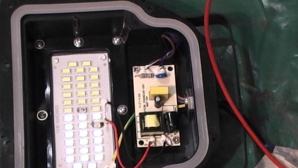
Low-power models often lack a power supply. In such cases, an LED-type driver is used instead of the unit. Since the diode is not able to receive power directly from the network (an alternating current is needed, different from the network one), then the driver is involved. The device operates based on operating temperature and time by varying the output current to the LED.
To replace the driver, disassemble the floodlight to set the technical parameters of the driver, and then contact the store. Just as with the power supply, you can select the appropriate driver from another device.
The most common cause of floodlight malfunctioning is overheating of the sensor, which leads to blown fuses. The searchlight is disassembled, after which the damaged matrix is taken out. To do this, unscrew four screws and unsolder the conductive parts. Next, a layer of thermal paste is applied to the LED and the conductive parts are soldered back. The operation is completed by screwing the matrix into place.
In some cases, the wiring in the die goes through the holes in the substrate. It acts as a matrix heatsink. In the transition areas, the wires must be covered with an insulating layer (first of all, we are talking about the plus wire). This will avoid a short circuit to the device case.
Advice! Before replacing the matrix, clean the substrate and the area where it will be installed. It is recommended to treat these places with a heat-conducting compound.
The shape of the matrix cannot be violated. It is recommended to use only "native" screws in order not to damage the structure. Also, do not forget about the polarity: red wires - plus, black or blue - minus, green-yellow wire is directed to the case.
If at least 2-3 burned-out diodes are found, you should not wait for the matrix to completely burn out. In any case, the device is no longer able to function normally, as a result of which the drivers and the voltage converter will soon fail.

Note! If the matrix does not work with the filled compound element, it cannot be restored.
If, when checking the board, obvious signs of burnt-out elements are found, the device will need to be repaired.The figure below shows the converter circuit for the spotlight.

Before replacing inoperative parts, the LEDs should ring. First, one of the legs of the board is unsoldered, since ringing the soldered elements will not give the correct result. If necessary, burned-out parts are replaced with new ones.
As an example, consider the repair of the SDO01-10 floodlight. The power of the device is 10 W. Visual inspection shows peeling of the protective coating on one of the floodlights. There are also dark spots on the light emitting surface of the matrix.
Repair of a matrix with a damaged LED emitter is possible, but such a part is not cheap. The cost reaches 40-50% of the price of the whole floodlight. In addition, the acquisition of a new matrix presents another difficulty - LEDs often lack markings. As a result, it is not easy to find out the type of emitter.
To simplify the task, we install the driver of the floodlight from the burned-out matrix to the luminaire with a working matrix. On the old driver, the protective resistor has burned out (its nominal value is 1 Ohm), which indicates a breakdown of the diode in the diode bridge at the transition from the key resistor to the control resistor. However, replacing the driver did not restore the functionality of the spotlight.

After further verification, a break in the optical feedback pair was detected. Replacing the pair gave a result - the lamp worked.
The subject of consideration is a model of a powerful searchlight SDO01-30. Devices of this type are used to illuminate large rooms (for example, for industrial purposes).
First, we remove the rear panel from the spotlight and carry out a visual check of the state of the radio components on the printed circuit board. We pay attention to elements that have a suspicious appearance (carbon deposits, deformations, etc.).
Next, we inspect the printed circuit board (by pulling it out of the spotlight) from the semiconductor side. Inspection showed the presence of a pair of blown resistors: R8 (2 ohms) and R22 (1 ohm). Low resistance resistors most often burn out due to the high current passing through them in the event of breakdown of semiconductors or capacitors.

Next to the resistors is the field-effect transistor SFV4N65F. The ringing has identified its malfunction. Since the searchlight circuit was not available, we find out the values of the resistors that burned out by disassembling a working lamp of the same model.
We solder the failed resistors, as well as the transistor. We replace them with new parts.
Some helpful tips for repairing LED floodlights:
- When replacing a matrix, be sure to pay attention to the polarity.
- It is imperative to remove cured heat transfer paste underneath the die.
- Degrease the surface with alcohol.
- When soldering, there is no need to overheat the surface. Soldering time - up to 2 seconds. If the matrix is overheated, the crystals will be destroyed or their new characteristics will not allow the projector to function normally.
- To repair a high-power floodlight, the knowledge used in the repair of low-power fixtures is enough. There are no special differences between devices of different capacities.
- If the matrix with a large number of diodes is not filled with a compound solution, it will be necessary to replace the inoperative diode. A microsoldering iron is required to complete the operation. You need to work carefully so as not to overheat the crystals.
- If it is impossible to see the denominations on the burned-out resistances, you cannot do without instructions for the searchlight. It must contain the relevant data.
Anyone can fix a spotlight. However, repair work requires at least basic knowledge of electrical engineering, as well as skills in handling a soldering iron and multimeter. You also need to be able to read diagrams in order to understand the design of a spotlight.
Frequent problems with lighting at home unwittingly require an independent troubleshooting. Agree, it is rather inconvenient to regularly invite a specialist to bring an LED or any other type of device into working form. To avoid such discomfort, we suggest that you learn the basics on how to repair LED floodlights yourself.
LED floodlight is one of the demanded and popular devices used to illuminate the local area. This tool is quite convenient to use, but sooner or later it will require repair. Therefore, it is so important to know the skills to correctly identify a malfunction, eliminate dysfunction and be able to return the device to its normal state.
Attention! Basic LED floodlights do not provide for replacement of light sources with another with a different power.

Often, the breakdown of an LED flashlight occurs due to overheating of the matrix. Overheating will blow the fuses. Thus, the following are considered as indirect reasons leading to the dysfunction of the device:
- short circuit;
- connection of overcurrents;
- overvoltage;
- connecting to the wrong network;
- non-observance of the device connection diagram.
Let us consider how a matrix defect is formed in more detail. The Matrix is a device powered by crystals. As a rule, there are dozens of them, and in case of failure of three or five crystals, the device continues to work in the same mode. Complete combustion of the matrix requires intervention. In such situations, a complete die replacement is ideal.
Important! In the process of repair work, the conductors of the searchlight should be additionally insulated.
Also, in almost all cases, the LED sources fail to work solely due to a malfunction of the drivers that feed the crystal surface of the floodlight. If your device becomes unusable during the warranty period, at the point of sale, you should be assisted and have the device replaced free of charge. Otherwise, you will have to resort to repairs yourself or pay for specialists.

To access the interior of the spotlight, you need to unscrew the back cover
Before proceeding with the repair work, you should acquire the necessary tools, as well as clarify the cause of the malfunction of the LED floodlights and carry out their elimination properly.
Chinese-made LED devices with a total power of 10 watts are considered frequent contenders for repairs, therefore, consider troubleshooting using the example of such a device. Let's get acquainted with the algorithm of actions:
- We detach the cover of the device case to get to the internal mechanism.
- Remove the glass cover and light diffuser.
- We unsolder the LED source from the matrix.
- We solder it to the new workable crystal panel.
- We fasten each bolt, check the spotlight with a multimeter. If the dial shows the working position, then we fix the flashlight in its place and enjoy its further work.
It's important to know! Polarity must be observed before installing a new matrix.

After disassembling the spotlight, you can start repairing
We draw the attention of beginners, after eliminating the malfunction, you should proceed in the reverse order. In addition, there is an opportunity to find out malfunctions on the following grounds:
- flickering of a light bulb;
- dull burning;
- changing the shades of the LED;
- deformation of wires and insulation failure.
The device works thanks to the joint work of several installed systems: optics, power supplies, drivers and heat sinks. Inside the case are LEDs and small electronic components.The power supply drives the voltage to the LED element, which converts the current into light beams, due to which the floodlight shines.
Attention! Do not open the sealed housing of the LED floodlight unnecessarily.
After you have repaired the LED floodlight and made sure it works, you can slightly improve the device. In some devices that normally operate under 220 volt power conditions, a rectifier and stabilizer are usually not installed. Carrying out repairs yourself, such devices are very easy to install. To do this, you should connect in series the pairs of LED sources, which are turned on in opposite directions, and a ballast capacitor should be applied to them.
Watch a small video tutorial on how to repair LED spotlights with your own hands:
LED floodlights are very popular today. But, like any electronics, spotlights break down relatively often. Today's article will be devoted to the repair of LED floodlights with your own hands.
The whole theory on the device of LED floodlights and terminology, and here is the practice for home craftsmen.
First of all, you need to make sure that 220 V power is supplied to the driver. This is Azy.
Let me remind you that the word "driver" is a marketing ploy to designate a current source designed for a specific matrix with a specific current and power.
In order to check the driver without an LED (idle, no load), just apply 220V to its input. A constant voltage should appear at the output, a value slightly greater than the upper limit indicated on the block.
For example, if the 28-38 V range is specified on the driver unit, then when turned on, its idle output voltage will be approximately 40V. This is explained by the principle of operation of the circuit - to maintain the current in a given range of ± 5%, with an increase in the load resistance (idle = infinity), the voltage must also increase. Naturally, not indefinitely, but up to a certain upper limit.
However, this test method does not allow us to judge the health of the LED driver by 100%.
The fact is that there are serviceable blocks that, when turned on without load, without load, either will not start at all, or will give out something incomprehensible.
I suggest connecting a load resistor to the output of the LED driver in order to provide it with the desired operating mode. How to choose a resistor - according to Uncle Ohm's law, looking at what is written on the driver.
LED - driver 20 W. Stable output current 600 mA, voltage 23-35 V.
For example, if Output 23-35 VDC 600 mA is written, then the resistance of the resistor will be from 23 / 0.6 = 38 Ohm to 35 / 0.6 = 58 Ohm. Choose from a range of resistances: 39, 43, 47, 51, 56 Ohm. The power must be adequate. But if you take 5 W, then it will be enough for a few seconds to check.
Attention! The driver output, as a rule, is galvanically isolated from the 220V network. However, you should be careful - there may not be a transformer in cheap circuits!
If, when connecting the required resistor, the output voltage is within the specified limits, we conclude that the LED driver is working properly.
You can use a laboratory power supply for testing,. We supply a voltage that is obviously lower than the nominal value. We control the current. The LED matrix should light up.
There are situations where there is an LED chip, but its wattage, current, and voltage are unknown. Accordingly, it is difficult to buy it, and if it is in good working order, it is not clear how to choose an adapter.
This was a big problem for me until I figured it out. I am sharing with you how to determine by the appearance of the LED assembly what voltage, power and current it is.
For example, we have a spotlight with the following LED assembly:
9 diodes. 10 W, 300 mA. In fact - 9 W, but this is within the margin of error.
It gave the fact that diodes with a power of 1 W are used in the LED matrices of the floodlights.The current of such diodes is 300 ... 330 mA. Naturally, all this is approximately, within the margin of error, but in practice it works exactly.
In this matrix, 9 diodes are connected in series, their current is one (300 mA), and the voltage is 3 Volts. As a result, the total voltage is 3x9 = 27 Volts. For such matrices, you need a driver with a current of 300 mA, a voltage of about 27V (usually from 20 to 36V). The power of one such diode, as I said, is about 9 watts, but for marketing purposes this floodlight will be at a power of 10 watts.
The 10 W example is a bit atypical due to the special arrangement of the LEDs.
Another example, more typical:
You have already guessed that two horizontal rows of dots of 10 pieces each are LEDs. One strip is offhand 30 Volts, current 300 mA. Two strips connected in parallel - voltage 30 V, current twice as much, 600 mA.
Total - 50 W, current 300x5 = 1500 mA.
Total - 70 W, 300x7 = 2100 mA.
I think it makes no sense to continue, everything is already clear.
It's a little different with LED modules based on discrete diodes. According to my calculations, one diode there, as a rule, has a power of 0.5 watts. Here is an example of a GT50390 matrix installed in a 50W floodlight:
Navigator LED floodlight, 50 W. GT50390 LED Module - 90 Discrete Diodes
If, according to my assumptions, the power of such diodes is 0.5 W, then the power of the entire module should be 45 W. Its circuit will be the same, 9 lines of 10 diodes with a total voltage of about 30 V. The operating current of one diode is 150 ... 170 mA, the total current of the module is 1350 ... 1500.
Who has other thoughts on this matter - you are welcome in the comments!
It is better to start repairs by looking for an electrical circuit of the Led driver.
Typically, LED floodlight drivers are built on the MT7930 ASIC. In the article about the Device of searchlights, I gave a photo of the board (non-waterproof) based on this microcircuit, again:
Navigator LED floodlight, 50 W. Driver. GT503F board
Attention! Information on driver circuits and a little more repair!
There are no special tricks when replacing the LED matrix, but you need to pay attention to the following things.
- carefully remove old heat transfer paste,
- apply heat transfer paste to the new LED. It is best to do this with a plastic card,
- fix the diode evenly, without distortions,
- remove excess paste,
- do not mix up the polarity,
- do not overheat when soldering.
When repairing an LED module consisting of discrete diodes, first of all, you need to pay attention to the integrity of the soldering. And then check each diode by supplying it with a voltage of 2.3 - 2.8 V.
If you need quick repairs, then it is best, of course, to run to the store across the street.
But if you are engaged in renovation on an ongoing basis, then it is better to look where it is cheaper. I recommend doing this on the well-known Aliexpress website.
I give several links for acquaintance and an example, there are many interesting things, including descriptions, photos and selection.
- Led Chip large selection from 10 to 100 W, from 48 to 360 rubles.
- Powerful LEDs.
Drivers for LED floodlights, for different powers:
- 30W waterproof DC power supply,
- 50W waterproof DC power supply,
- Waterproof outdoor LED drivers 10, 20, 30, 50W DC.
And who does not want to repair, you can immediately order ready-made:
LED street floodlights:
- Street floodlights from 10 to 50 W,
- Floodlights waterproof flat from 10 to 100 W, you can set LED Chip + Driver.
To complete the picture - a video from my colleagues, they share their experience:
This concludes. I call on my colleagues to share their experience and ask questions!
Previous work generously supplied me with the corpses of LED lamps and fixtures. Without going into technical details, more than 99% of what is sold everywhere is frank slag, fundamentally unable to work for a long time due to clearly insufficient or even missing cooling.
Here's an example of a complete slag: a bullshit pure plastic "radiator". the result is predictable: the LEDs are burnt out, the crystals are blackened, and self-evaporated
“Old-style” LED floodlights with a solid-cast aluminum body-heat sink were relatively well made, but they are rapidly disappearing from the market.
old spotlight
old spotlight
But, apparently, the sellers and the Ketays thought that so much luminine was too fat, and they optimized these projectors. Now on sale everywhere "new design" floodlights with a plastic housing and a separate radiator.
30W new design floodlight
Cartridge supplied for sizing purposes. The radiator has a finning area of about 200 sq. Cm. The result is predictable: heating of the radiator in the region of + 100gr, rapid degradation and failure of LEDs
pay attention: there are 60 pcs of LEDs 0.5W type 5630. diodes are used 100%. Stock by mode? What nonsense, have not heard. And also my teacher in electronics in the distant 80s used to say that components at> 60% of extreme modes are used, either idiots or greedy bourgeoisie.
Here the circuitry of the emitter is as follows: 2 parallel groups of 30 in series 5630. Forward voltage in the region of 90V at + 25g r, and current 300mA.
The LEDs are mounted on a luminescent board, which is screwed only in the corners. Loose fit.
the result is in the photo. For a paltry 100 hours, the phosphor has already turned badly black, several diodes have burned out, burning black holes in the phosphor. The driver is also dead. Groups of LEDs are re-connected by me in series, the driver is down-greyed to a blunt capacitor.
It was empirically found that such a radiator is able to maintain a sane temperature on the crystals in the region of + 80g and + 60g on the radiator, with a power of only 1/3 of the nominal power of the searchlight. What I have done, the current is reduced by three times.
Roughly the same picture for other powers of this type of floodlights: terrible overheating and rapid drying
morality? avoid buying these “new style” spotlights, if possible, look for “old style” solid-cast spotlights.
by the way, pay attention to the drivers of different spotlights. They do not have a capacitor in the rectifier as a class. This is how manufacturers are fighting for a decent cos phi. Needless to say, the 100Hz output ripple is huge. Capacitors at the output do not save. Do not use such spotlights where you work for a long time, take care of your eyes. At a minimum, it is useful to add electrolyte there to the rectifier, at least 10 μF for every 10 W
Also note that all drivers, and LED lamps too, are made according to the “step-down” scheme. there is not a transformer, but a choke, and there is no decoupling from the network! Be extremely careful! The crystal-to-substrate insulation is clearly not rated for line voltage.
LED Floodlight Drivers
The driver's power must match the power of the spotlight, more precisely, the matrix in the spotlight. Do not rely on the power indicated on the body of the floodlight! We were repeatedly brought to repair a searchlight, proudly in a half-case marked with 50W with a 30-watt driver and a matrix inside. Installing a 50-watt driver in such a product will not end well. It is imperative to read the marking of the burned-out driver.
The driver must physically fit inside the LED spotlight. And you still need to lay the wires.
The exact dimensions of the drivers are indicated on our website.
The value of the output current is always indicated on the driver housing. This is the current that the driver will supply to the matrix. This value varies from approximately 300mA to 3000mA and should match the supply current of the matrix. Deviations of more than 5% are unacceptable .
The driver's output voltage range is the two voltage values within which the driver tries to stabilize the current.
The numbers can range from 20 to 150 volts.
This range should coincide with the corresponding matrix characteristic, or, if it is unknown, the range of output voltages of the burned-out driver.
This parameter does not have to match as closely as the current value, but an approximate match should take place.
We manufacture different drivers for LED floodlights, not only for 220 volts.Therefore, when buying a driver, make sure that you are a driver for the input voltage you need - all drivers presented in this section are designed for 220, 127 and 110 volt networks.
For those who have not read, let me remind you briefly. Recently, a powerful 120 W LED floodlight was brought in for repair, it worked for only a year. As it turned out, his driver burned out. And there I began to whine about the fragility of switching power supplies and wondered about finding a simpler and more reliable solution. Today I decided to assemble and test the operation of the circuit with a quenching capacitor. A similar circuit is widely used to power LED spotlights.
Pre-calculated the capacity of the quenching capacitor according to the well-known formula
For the calculation, I took the following parameters:
Uc (mains voltage) = 220 V;
U (voltage at the input of the diode bridge) = 60 V;
I (LED rated current) = 1.8 A;
According to the calculation, it turned out that a capacitor with a capacity of 27 μF was needed. I ran through the bins, collected all sorts of different capacitors to provide the required capacity, and also experiment with the deviation of the capacity from the calculated value. To avoid misunderstandings, I measured the capacitance of all capacitors with an E7-16 immitance meter.
Despite the venerable age of some specimens, the capacity practically corresponded to the indicated one.
Soldered the circuit. In order not to bother too much, I used the power unit from the computer power supply board. The result is such a construction
It was interesting to find out - within what limits the current will change when the input voltage deviates by 20% from the nominal value with different values of the capacitance of the quenching capacitor. The experiments were carried out with LEDs preheated for 30 minutes. The measurement results were tabulated and presented in graphical form. During the measurements, the voltage across the capacitor C2 varied within 58 V. 62, I decided not to enter these values into the table due to their slight change.
The graphs turned out to be linear
The native driver ensured that the current flowing through the LEDs was maintained at 1.8 A. According to various sources, the rated current of a 60 W LED is from 1.8 to 2 A, different sellers indicate different currents. We will assume that a current higher than 1.8 A is undesirable.
| Video (click to play). |
If you choose a capacitor with a capacity of 24 μF, then when the input voltage rises to 260 V, the current through the LEDs will not exceed the nominal value. In normal mode, with an input voltage of 220 V, a current of 1.5 A is provided, which corresponds to a power consumption of 90 W. With a rated current of 1.8 A, the rated power is about 110 W. Thus, with an input voltage of 220 V, we have a power reduction of 20 W (18%) relative to the nominal value. On the one hand, a lower current value increases the service life of the LED, but leads to a decrease in the brightness of the glow, although this is not particularly noticeable by eye. It would be nice to measure the brightness with a suitable device, but it is not available.


