In detail: do-it-yourself 1zz engine repair from a real master for the site my.housecope.com.
Good day to all!
Celica T23, 1zz, 2000 year, contract soldier, I don’t know exactly what year (I bought the car in April 2012)
I bought it, could not get enough of it until I smelled how much oil it hawala. Approximately 500-700 grams per 100 km. - I got into a panic.
For work on capital, we are asked for 30-35t.r., but there is still no money for these expenses, and after reading articles, a forum, e-books, I decided to sort it out myself (fortunately, my hands are not growing out of f ...)
Mainly relied on this article: 20_rem_zz-1.htm
I took off everything, signed it, laid it out like all the rules so far, I had to jump around the gur pump, I didn't know which way it was being removed and pulled it in the wrong direction.
It's time to take off the head - and there is an asterisk, I went and bought it.
8 bolts (or pins, they are correctly called) unscrewed, two stuck - tore off the edges.
Well, he tupanul, an acquaintance welder was nearby, asked him to hook the key to the bolt. He promised that he would do everything in the best possible way!
What I later regretted ((.
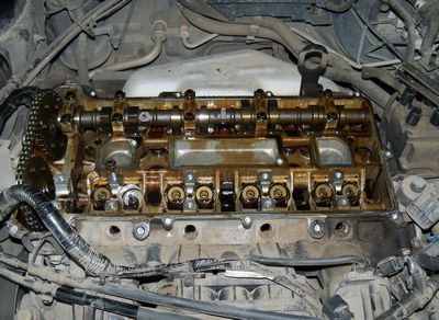
welding knocked the head, namely the place where the exhaust camshaft lies next to the pulley, on the inside:


I think, to hell with those tags that are inside, but what to do with those that are on the rubbing surface? Is it possible to somehow undermine and how to do it?
It may look scary in the photo, but in fact the dots are very small, on the upper corner they are about 0.5 mm high,
but on the plane below it is not felt at all, maybe the metal just darkened.
Welding didn't help in the end. took out a drill and drilled with the 9th drill in 5 minutes! I would have known that everything is so simple, I would never have got there by welding. ((
He took off the head and turned away the pins with his fingers - i.e. the bolts stuck to the point of contact of the head of the bolt with the head itself.
| Video (click to play). |
Next, I ask you to make a diagnosis from the photo and give recommendations or advice on subsequent manipulations.
Valve:


like not so shitty.


And another question is how to dry the valve? and dry up back?
cylinders:


like a hone like in the photo on all 4 cylinders,
I do not know if it can be considered that the hon is normal.
A long time ago, in a distant galaxy, one of our regular customers decided to buy an SUV, but since he had a limited budget, he hesitated between an almost new Niva Chevrolet and a not young RAV4.
And then, finally, it happened. We were visited by a 2001 RAV4 with a 1.8 liter 1ZZ-FE engine and a heartbreaking story of a happy new owner. Since a car was bought in the neighboring region, at the local service station they pulled up on a lift, measured the compression, which turned out to be 11 in all pots and, having put an assessment, let it go home. But it was not there! On the way home, it turned out that the car was eating oil in buckets. The reason lies in a factory defect. Until 2004, on 1ZZ-FE engines, there were only two drainage holes in the groove of the oil scraper ring of the piston, at a mileage of 140,000 they coked up and the rings lay. Later, four holes were made in the piston on each side, which solved the problem. Therefore, there is only one way out: we replace the old pistons with pistons of a new sample, as well as rings and connecting rod bushings. Piston kit 13101-22180. The selection of spare parts is well written in this article. By the way, the previous owner aggravated this situation by pouring in his dear oil L ... (well, you get the idea) - you must not love the Japanese so much.
Disconnect the negative stamp of the battery. We remove the ignition modules, the air filter with the housing. We drain the antifreeze and oil. Disconnect the fuel line.
Disconnect the injector connectors and remove the fuel rail. The sealing rings will have to be replaced.
We disconnect all pipes coming from the throttle assembly, unscrew two nuts and three bolts for 12 intake manifold.
We remove the manifold together with the throttle. We disconnect all electrics from the generator and starter, as well as from the air conditioning compressor and DD.
Also, everything is from the side of the box and we remove the wiring harness, so that it does not interfere.
We remove the generator, pump, front timing chain cover and the chain itself with stars. Details in the article on replacing the chain on the 1ZZ-FE engine.
Disconnect the front pipe from the exhaust manifold.
In several passes, first we loosen and then unscrew the 19 bolts of the camshaft bearing caps, always in the specified sequence.
Remove the bearing caps and carefully lay them in the same way as they were removed.
We remove the camshafts. The intake valve shaft is longer.
In the same way, in several passes, we loosen and unscrew the 10 bolts securing the cylinder head. Mandatory in the specified sequence. Ignoring the last rule, you run the risk of at least taking the head for grinding, and at most buying another.
We remove the washers with the bolts, as well as mark and remove the valve pushers. We remove the cylinder head.
We unscrew a lot of bolts and two nuts of the oil pan and remove it. It is on sealant, so you have to tinker.
We unscrew two bolts of each connecting rod cover and carefully, loosely remove it. The liner should remain in the lid. If not, remove them from the crankshaft and put them back into the cover. We mark from which cylinder each cap. Don't be confused. The front of the bearing cover is marked with a shimmer.
We push the piston with connecting rods upward.
We see the buried oil scraper rings.
The rings were carbonized to such an extent that I pried them out with a knife, the drainage holes were tightly clogged.
While we are dealing with the piston, in the next box, the specialist Serega is conjuring over the head. Having died out of the plane, it pleases us with the fact that it is not necessary to give for grinding.
But what happened to the valves and channels. No comment here.
Well, how can the youngest clean it all for me, but they say we have democracy. I cleaned, Seryoga changed the valve seals. It was getting dark.
Having received the assembled cylinder head, I went to assemble the engine. Well, everything here is like in a book.
If the connecting rod bearings have scuffs, replace them.
We will not grind the crankshaft, since the client is already over budget. For the money that a full capital costs, you can bring in a 2005 contract soldier. There is a marking on the inserts on the back side, and we order new ones according to it.
We knock out a finger from the old piston, having previously picked out the retaining ring. We sweep on the connecting rod in front, as well as the cylinder number.
We put a retaining ring on one side of the piston.
We combine the marks in front of the piston and connecting rod. Lubricate the new piston pin with engine oil and, using the thumb of the right hand, press the piston into place.
We put on the second retaining ring. In the same way, all four.
We check the clearances in the new piston rings. We insert the rings in turn into the cylinder where they will subsequently work.
Push the piston to a depth of 110 mm.
The minimum clearance for the first compression is 0.25 mm, for the second - 0.35 and for the oil scraper - 0.15 mm. If you have to grind less. Maximum 1.05 1.2 and 1.05 mm respectively.
Some rings have markings that should point up. We put everything in its place, the first compression, the second, two oil scraper scrapers and an expander.
Degrease the connecting rod and bearing surfaces. We put new liners in the connecting rod and cover. We do not lubricate with oil and make sure that nothing gets under the liners.
We unfold the rings with locks as shown schematically in the photo.
1 - lock of the first compression ring
2 - lock of the lower scraper of the oil scraper ring
3 - lock of the second compression ring
4 - lock of the upper scraper of the oil scraper ring
Lubricate the ring holder with clean oil, squeeze the rings and put the piston in the cylinder.Don't forget about the "before" label.
Push the piston with the wooden handle of the hammer. Lubricate the crankshaft journals with clean oil, as well as the liners. We put in place the connecting rod bearing caps. Don't confuse numbers and directions. We tighten the bolts by hand. We tighten all the bolts to a torque of 20 N * m, after which we turn it another 90 degrees. We turn the crankshaft, it should rotate easily without jamming. We put in place the oil pan and a new head gasket.
We clean all the head bolts, as well as the holes in the block from oil and dirt. We put the cylinder head in place. We tighten the bolts in several passes, in a certain sequence to 49 N * m and turn them 90 degrees.
We put in place the valve pushers. We lubricate everything with oil.
Camshafts, face key must point up.
We install the camshaft bearing caps in accordance with the direction and number. Intake I2 I3 I4 I5 and exhaust E2 E3 E4 E5. The arrow indicates the direction "in front".
Tighten the bolts evenly in the sequence shown. After preliminary tightening of bolts No. 9, we tighten all the rest in several passes. The tightening torque of bolts No. 9 is 23 N * m, the rest - 13 N * m.
Next, we install the timing drive, as described in the previous article. Fill in good new oil and antifreeze. To remove the airlock, you can remove the stove hoses one by one, they are just at the very top. After the final assembly, without connecting the injector connectors, we turn the engine with the starter, several approaches for five seconds. We connect the injectors and, by squeezing the clutch, start. Before starting, my candles were flooded twice. After it starts, we milk it to idle, turn off, check antifreeze, top up. And so several times. After the airlock has been removed, we warm it up until the cooling fan operates and turn it off. Let it cool, check the antifreeze and repeat two or three more times. After that, you can drive, but only the first 200 - 300 km we save the engine, we try not to give more than 3000 rpm and the main thing is not to overheat. Further at will, but it is better to roll the first thousand calmly.
Good luck on the road. Not a nail, not a rod.
Foreword to the question. The car was bought in March 2007, with a mileage of 78 thousand km. After 3 years of operation on the roads of the Russian Federation, the mileage was 172 thousand km, that is, more than 30 thousand per year. He did not regret the car, ran a lot between cities, often over 140 km / h, overheated several times, the topic of a fan malfunction in the wrong direction, I hope I made you happy


So, for repairs, you need a week in a warm garage with a pit, a printed manual for the car, 4L oil (1500), C110 filter (130), a good American sealant (250), a large carbcliner (140), a set of piston rings (2050), adapting for planting pistons in wells (400), diesel fuel and gasoline (5 liters each), a repair kit for all possible rubber bands / gaskets for 1ZZ, oil-reflecting caps included (4500), ring wrenches, heads, screwdrivers, 12-sided keys ( 2pcs) and heads (2pcs) sizes 10 and 12 for the piston group (350)
PS: I realized one thing for myself, 1zz-fe is not one-time


I will say right away: the lathe came in handy, it was used to grind a device for drying the valves (and further removing the valve stem seals) - we did not have a special puller.


further in order: we studied the manual, removed the right front wheel, removed the plastic protection from the bottom, right and left
the main goal was: to change the oil scraper seals (they were stiffened like plastic, did not perform the function), replacement of piston rings (the third row lay most of all, the first two on top were simply worn out, without an oil scraper lip, but the rings were more or less in order and in place ), replacing the oil seal of the front engine cover (oil on the housing at the bottom near the chain) the chain itself was in order, not stretched.
further: DISCONNECTED AND REMOVED THE BATTERY, removed the cover layer, candles, coils, wires, disconnected all the electrics, sensors, air in the upper part, all tubes, disconnected a bunch of sensors, removed the nozzle block (4 pieces green).
after which we remove the intake manifold assembly, a bunch of other hoses, and tear out the throttle body (the inside on the back side is really dirty)
most exciting moment: open the top engine cover. so much der ”ma didn’t expect to see


due to wear, the entire motor from below near this roller and the chain tensioner is covered in oil. change when we remove the front cover of the engine. And now about this roller (which glitters, the power steering roller) - 3 bolts were unscrewed for a long time, 3 hours on the first day, 2 hours on the second. the main problem is that it does not allow you to remove the front cover. and if you unscrew these bolts, you still need to be able to knock them out into the pallet, this is very difficult


we remove the pallet and again we are amazed at the amount of dirt. the iron mesh of the oil receiver is completely clogged
I forgot to mention, all attachments that interfere with work, for example, a kondeya compressor, a generator, we remove the right engine support and either move it to the side, or remove it (the support is accurate), then we use a small additional jack (point hydraulic) to raise / lower the engine itself
a 12-point head (I don't remember 10 or 12) is needed to unscrew the connecting rods and push from below, removing the pistons
we remove the bolts on the right that interfere with the removal of the cover, unscrew the studs, having previously screwed on them 2 nuts by 10
Castrol 5v40 oil, never again! further: remove the front cover of the engine and see how much dirt there is.

remove the chain and two camshafts. on the fasteners at the shafts, letters and numbers are knocked out in order from the front cover. we evaluate the condition of the shafts (ex), but everything that is nearby needs to be torn off. to remove the block head, you need a 12-sided key (10 or 12, I don’t remember) you cannot tear off a simple hexagon, it will only get worse
remove the head of the block and assess the condition of the piston wells (hon is good, without scoring, even) and the condition of the pistons themselves (soot is terrible)
we tear off the pistons (with old rings and carbcliner, solvent, the rings are stuck, but they were worn out, a little alive) and the front cover of the engine from dirt (diesel fuel, an iron brush, we wash it with gasoline, we find a number on it, change the oil seal and some other rubber band)
to remove the block head in this way, together with the exhaust manifold, I had to tinker. there everything sour from the high temperature, especially the junction of the collector with the exhaust tract (the gasket is a thick metalized ring, for some reason it did not fit from the kit, they put the old one, wrapping asbestos on it, tightly in Russian)
under these 16 dimes there are valve stem seals (which have become hardened to change to new ones), but in order to remove / put them you need to adapt (or buy, or grind on a lathe)
we begin to assemble the engine back (we CAREFULLY read the manual, we are looking for marks on the crankshaft sprockets, on the VVT wheel, the chain mark), we put the pistons with new rings using this thing
IMPORTANT!! when you tighten the belt tensioner pulley (the topmost one), do not overdo it, but you cannot understretch either


I don’t know what your name is, but I must say that well done, such a report is of the highest class, I’m not the first day associated with motors, and I’ll say that. There are not many words, the pictures show that the development of the liners is significant, did you take measurements?
the glasses need to be changed, we can not everything, but they have production, it was necessary to measure the gaps before parsing, there such a situation can be changed in places, but you have to change something, they are all the same, I mean the Japanese of our years, the current price tags are different, it is necessary micrometer and a ball to measure the thickness of the glass, taking into account wear, if your father-in-law is special, then you will understand.
if there is a hone along the entire diameter and on all boilers, then you are in luck.
And about such dirt, here I think it's not so much about the quality of the oil as about the driving style (short “runs” without normal warming up in winter) and our fuel there: wacko1:
.
what glasses are we talking about? is there a solid aluminum block?
as with us, you can't find washers on 1zz (for adjusting the valves)
once again: glasses are used instead of 1zz washers. can be found, for example, in the Exist. All dimensions (i.e. bottom thickness)
13.09.2013
Contract engine will give a second life to your beloved Toyota
According to statistics, the most popular foreign cars in Russia are Toyota and Subaru. Those who cannot buy a new model buy used cars. They are relatively inexpensive and serve. >>>
02.03.2012
Photo report on flushing the throttle valve of a motor type 1ZZ-FE
Well, I decided to clean the throttle valve for 1ZZ 1.8 liters. Sorry if something goes wrong and for such a clean engine REPORT: In photo 1, what was needed for work In photo 2, a general view. >>>
155 comments | Write a comment
May 31, 2011
Photo report on replacing fluid in the automatic transmission of Toyota Allion
I did this procedure today, and so on in order Filter Gasket Rings Drain the oil Remove the pan Filter Without filter Set. >>>
1623 comments | Write a comment
09/02/2010
Error 33 - idle valve, floating engine speed.
So, friends, good time of day. I decided to share a report on the procedure I just performed on the 1zz engine (it is also suitable for the rest). Symptoms: - when starting after a long stay sometimes. >>>
100 comments | Write a comment
08/31/2009
Photo report on flushing the throttle valve of a D4 1AZ-FSE 2.0 liter engine
To begin with, I did not find on the Internet a single photo of a report on flushing the throttle valve on D4 1az fse 2.0 liter engines. Tolley was looking badly, toli really do not exist yet. >>>
281 comments | Write a comment
30.09.2008
Report: Replacing antifreeze 1ZZ-FE Allion / Premio
SO, materials: 1. Distilled water - 20L. 2. Antifreeze concentrate TOYOTA LLC 08889-00115 (2l) - 2 cans. (2 * 540 rubles) 3. A 5 liter bath for draining the old one. >>>
17 comments | Write a comment
December 27, 2007
Toyota NZ Series Engines
In the class “up to 1500 cm3”, the classic ones were also replaced by new subcompact engines of the third wave. Engines of the NZ series repeat the absolute majority of the solutions of the ZZ series considered. >>>
8 comments | Write a comment
December 27, 2007
Toyota 1ZZ-FE engine. No room for error
It's time to talk more or less in detail about Toyota engines of the new generation and, first of all, about 1ZZ-FE, the most common of them. Every day everything comes to the country. >>>
23 comments | Write a comment
May 31, 2011
Photo report on the complete fluid change in the U341 automatic transmission on the 1ZZ-FE engine
So, for those who wanted to get to the master class, but could not - a photo report on the complete replacement of the slurry in the U341 automatic transmission on the 1ZZ-FE engine. The experimental car was the Toyota Premio of the forum member mayorovka. Cooking. >>>
1623 comments | Write a comment
Group: Users
Messages: 4714
Registration: 30.7.2008
Town: Kiselevsk Chemical Region
Auto: Toyota Opa
Gender: Male
Has thanked: 217 times
I hope that I will be able to write a report on the overhaul of 1ZZ-FE, experience in such matters is zero.
I was preparing for the capital for a very long time and carefully, I hoped to do only by replacing the piston rings, but His Majesty, by chance, slipped me an engine with cylinders in a hopeless state.
Well, all in order.
The following parts were purchased.
SPARE PARTS
Toyota engine piston 13101-22032
Rings piston Toyota 13011-22221
Oil scraper cap, exhaust Toyota 90913-02111
Oil scraper cap, inlet Toyota 90080-31061
Exhaust manifold gasket Toyota 17173-22010
Intake manifold gasket Toyota 17171-22030
Toyota cylinder head gasket 11115-22050
Connecting rod bushings
Basic liners
Valve cover gasket Toyota 11213-22050
Exhaust gasket Toyota 17451-21030
Front oil seal (crankshaft) Toyota 90311-38089
Rear oil seal (crankshaft) Toyota 90311-76001
Oil filter Micro
Oil 5l synthetic Ravenol
Chain
TOOL
The torque wrench was already with a large arrow in the entire handle (I didn't like it) I took it from a neighbor with a dial.
Allen key
5 sided key
Spanner head (12 mm bi – hexagon wrench) Toyota 09013-7C310
Bit for loosening the head bolts from the Overhaul OH3582 set, type M12 fitted by Constantin 71
12-point head 10 mm, for loosening the bolts of the connecting rod caps
Homemade dryers
Oil control valve remover
Mandrel for installing valve stem seals
ADDITIONAL MATERIALS
sealant
thread lock
polishing paste
Metal marker for signing parts (helps with assembly)
CLEANERS
acetone
carburetor cleaner С-Сliner 2 cylinders
engine cleaner Profam 1000 2 balloons
solvent 646
Much has been written about how everything is sorted out. Something, in the report I will use from previously written by others (a little piracy)
https://my.housecope.com/wp-content/uploads/ext/2991/forums/index.php?showtopic=2626
As always, we remove the battery, wipers, air, drain the antifreeze. Remove the throttle valve.
We unscrew the injector, the manifold, remove the drive belt, generator, air conditioner compressor.
Remove the right wheel to remove all plastic sheets. From there we get to the crankshaft pulley and unscrew it. I did not turn the starter, but after removing the plastic plug between the internal combustion engine and the automatic transmission, I stuck a triangular file in the flywheel teeth, the whole crankshaft is blocked.
We proceed to the removal of the hydraulic booster. Having unscrewed two long bolts, it was not possible to remove it until the front cover of the internal combustion engine was loosened. The hydrach himself fell out of his seat.
Having jacked up the engine, remove the belt tensioner, right cushion and now you can unscrew the entire side cover. We see this picture.


Next, we remove the camshaft locks and take out the shafts themselves. It is necessary to pack in the order in which everything was assembled. We unscrew the long 10 bolts of the block head and remove the head. This is the picture in my engine. On 1 cylinder there is finally no hone, on 2 and 3 more or less it is normal, and 4 cylinder 50 * 50 hone is rubbed in places to the mirror
link
We unscrew the flywheel from the torque converter - six bolts.
link
An important point. It is necessary to measure the axial play of the crankshaft. 0.03 to 0.30 mm.
Measurement showed 0.18 mm, which is quite within tolerance and replacement of persistent half rings is not required.
link
I will not repeat about my attempts to decarbonize pistons with chemistry. Who is interested in reading here.
link
We unscrew the Flywheel.

The information contained in it has been verified by the compiler on two machines. Good instruction. However, the author misses the need to replace the valve stem seals, and it is they, in the first place, that contribute to the penetration of oil into the combustion chamber and, as a consequence, the occurrence of rings. Therefore, the compiler took the liberty of slightly adapting the material for Toyota WISH and adding a little of his own.
Good day to you! If you are reading this article, it means that you, like me, were tortured by the zhor of oil and the rumble of the chain on the 1ZZ-FE.
The compiler takes the liberty of adding words Eugenio, 77 :
if the oil decreases, then either it leaks, or the engine "eats" it.
Oil consumption is possible:
a) through the crankcase ventilation system into the air filter or manifold - excess pressure in the crankcase - see piston, then see crankcase ventilation, in principle they are closely interconnected
b) through the valve stem seals (or a worn out valve sleeve) - it is determined in the following way: warm up the engine, smoothly unwind (at least 4 thousand), suddenly throw gas and look into the exhaust pipe, if after these manipulations the smoke has intensified for a while - end caps (increased vacuum sucked oil through them). the same is the “traffic light test”: drive on a warm engine, stop for a minute, then move off (more or less intensively) - if a gray cloud flies out at the start, and then everything is normal - the caps are similarly time to rest.
c) through the rings - if he eats too much, if he starts to smoke when the speed rises, if the compression has dropped (and when the oil is poured into the cylinder through the spark plug hole, it grows - just do not forget about the possible “oil compression”.
d) crack in the block - no comment.
I'll make a reservation right away: I didn't have a goal to do a major overhaul of the engine, so I only changed the rings. I did not measure anything, did not look at the gaps, did not change the caps. I was just curious to test the opinion that changing the rings solves the oil problem. It was for this purpose that I got into the engine. Most likely, I will definitely miss something in my story, make a mistake somewhere or call something different from what it is actually called 🙂 Don't judge strictly, the material is large, and I'm not a professional, you can't keep track of everything ... Well what, let's get started?
We jack up the right front, remove the wheel. Then, from below, we turn off everything that interferes with getting to the engine crankcase (protection, plastic mud flaps, etc.) The compiler had to order 2 pistons 90189-06013 because he did not understand how they were removed. Ni & clips 90467-07164
We turn off the drain plug, drain the oil. We drain the antifreeze from the block (there is a faucet on the back side, in the photo below) and from the radiator (drain plug at the bottom left).
I wound 3 turns of electrical tape around the tube and poured it into a clean container. About 2.5 liters have been drained.
Unscrew 2 screws and 2 plastic caps that secure the decorative cover, remove it.
Disconnect 4 connectors from the spark plug coils.
We unscrew the 2 nuts securing the strip with the wiring.
We unscrew the 4 bolts securing the coils and remove them. We turn out the candles.
Disconnect the ventilation hoses from the valve cover.
We unscrew the screws and nuts securing the valve cover, see if something else is screwed on that interferes - unscrew 🙂 Remove ...
Compiler's note: to reduce the likelihood of any debris getting into the engine, it is advisable to remove the cover immediately before disassembling the engine.
I advise you to unscrew the PCV valve, wash and assess the condition ...
You can read about the system of its work here
It's time to unscrew the bolt on the crankshaft pulley. Tightened from the heart, prepare a good cap and a long knob ... Direction - counterclockwise. According to the book, a special device is used for unscrewing it, which locks the pulley (in the photo below).
Of course, there was nowhere to take it, therefore, remembering the experience of the same bolt on the "eight", I simply stopped the flywheel at the junction of the engine and gearbox. Look from below, there is a plastic cover, remove it and insert something powerful between the teeth of the flywheel, well, like a large screwdriver. Make sure that it does not jump out during rotation, get out from under the car and go try to unscrew the pulley. The first time it will hardly be possible to fix the screwdriver so that it does not fall out ... It is optimal, of course, to have an assistant ...
We unscrew the bolt, remove the pulley. The key remains on the shaft, do not lose it. However, she sat tight with me and clearly was not going to fall out anywhere. We look around, assess the condition of the oil seal, whether oil is leaking from under it. If so, well, well, you will have to change. It is not difficult, the main thing is accuracy. When you put the pulley in place, wipe it from sand and dirt and lubricate the seat that is in contact with the oil seal with engine oil around it.
Now let's deal with the fuel rail, it also needs to be removed. Disconnecting the connectors from the injectors ...
Next, remove the black plastic piece 🙂 from the fuel line.
We pull it up, it snaps off. This will make it possible to rotate the fuel pipes relative to each other and take the ramp out of the working area. You can even disconnect this connection and remove the ramp completely - I didn't succeed 🙁 Even with the help of a smart book ...
We unscrew the fastening bolts, pull the ramp upwards and remove. (Again, in order to prevent dirt from entering the combustion chambers, it is advisable to clean the surface of the head near the nozzles from dirt (with compressed air or a brush) It is impossible to predict where the nozzles will remain, in the ramp or in the head, it is impossible, but most likely in the ramp.It is likely that there is pressure in the ramp and spraying around the gasoline cannot be avoided, prepare a rag or oilcloth and cover it at the time of removing the ramp, at least you will save yourself and the surrounding space from abundant sprinkling of gasoline 🙂
Do not forget to remove the 2 plastic bushings on which the ramp was attached
The injectors on the ramp will look like this 🙂
Pay attention to the rubber o-ring at the bottom of the nozzle. If it is not there, it is likely that it remained in the block head. There are 4 such rings, one per nozzle 🙂 In the manual, all O-rings (and indeed almost all the rubber bands that are in the engine) are strictly prescribed not to be reused. I don’t know, I don’t know, all my rings turned out to be soft and, in my opinion, quite suitable for further use. Look at your situation according to the situation ...
Immediately brief assembly recommendations. The places for the lower O-rings in the head of the block will most likely be covered in dust and dirt, everything must be carefully cleaned. We remove the rings from the nozzles, carefully clean them from dirt / sand. We wipe the nozzles themselves. Those interested can wash them, there is a material on this topic. Further, I would advise to lubricate the lower rings with ordinary engine oil and immediately install them in the block head. We also lubricate the upper O-rings, put them on the nozzles, lubricate again over 🙂 and install the nozzles into the ramp, as in the picture below. Then, the ramp assembly with the nozzles will be put in place, into the head, at the same time controlling whether the nozzles fall into the O-rings and, if necessary, adjusting the direction.
Next, remove the intake manifold. We turn off the fasteners. Then rely on your intuition, because the throttle valve block is connected to the manifold on the right, and it is almost impossible to describe in detail every wire and hose that fits there. Just see what is stopping you and disconnect.
The connectors are made according to the mind, it will not work to insert into the wrong slots. There is a gasket under the collector, it cannot be reused (again according to the book). I put in a new one, since it is inexpensive.
With a good spanner wrench (to break the edges as there is nothing to do ...) with an extension cord (because it's hard ...) slowly! squeeze the tensioner and remove the belt.
Unscrew and remove the right engine mount. Before this procedure, the engine must be slightly jacked up from below in order to avoid its subsidence due to the removal of the support. I advise you to choose the place for installing the jack responsibly, so that the jack does not interfere with the removal of the oil pan, and it was possible to still raise the engine to pull out the screw that secures the belt tensioner. More on this below ...
We unscrew the nut (upper arrow) securing the tensioner and the bolt (lower arrow) on which the entire tensioner structure is attached to the block. Here it will be necessary to raise the engine with a jack, because the bolt is long and it will not work to remove it without jacking it up. Remove the tensioner assembly. We assess the condition of the bearing. There was almost no lubricant in my, I had to fix this flaw 🙂 Now as good as new. We look carefully at the tensioner bushings, they may also need to be brought into a divine state. About this - closer to the end ...
We unscrew the 3 bolts and remove what the right engine mount was attached to.
In order to reduce the load on the remaining engine mounts when the chain cover was removed, I later put this unit back in place by simulating the thickness of the cover with nuts of a suitable width.
Unscrew 2 nuts and take out the hydraulic chain tensioner
We unscrew the 2 bolts and move the sensor aside so that it does not interfere 🙂
Minus 6 bolts - and the pump is in our hands 🙂 Do not lose the O-ring. Think about the prospects for its further use. If anything - a sealant is a good thing 🙂 I don't remember exactly, but 2 or 3 bolts - short , compared to the rest! Be sure to notice where they stood and when assembling, put them only in their places! I do not recommend screwing long bolts into short holes at all, you will not fully tighten it and there is a very real chance of damaging the cover.Well, or the bolt will break, as happened to me ... Pulling out the wreckage is a separate story.
The compiler was too lazy to drain the antifreeze from the lower hole of the radiator, so when the pump was removed, about 0.5 liters of antifreeze spilled onto the floor.
We unscrew the bolt securing the power steering pump pulley (we lock the pulley with a screwdriver, in place) and two nuts securing the pump itself. It is not necessary to remove it at all, let it remain on the bolts.
We unscrew the 2 bolts securing the generator, pull it off and take it to the side ...
In fact, the generator is easier to remove altogether. To do this, unscrew the common wire and disconnect the connector suitable for it.
We unscrew the 3 bolts securing the compressor, and, without disconnecting the hoses, carefully attach it to the lower radiator duct.
We unscrew the remaining screws / nuts / studs around the perimeter of the cover and, prying it off with a screwdriver, remove it. Pry gently without scratching the surface too much
Remove the asterisk below. During the subsequent installation, be careful, the letter “F” on it should be facing you.
Unscrew the bolt and remove the left chain damper.
Prying with screwdrivers (or just with your hands), pull the lower gear towards you. It is not at all necessary to remove it, the main thing is to pull it out to such a state that you can remove the chain. Pull out, remove the chain.
We unscrew 2 bolts, remove the right damper.
We unscrew the bolt and remove the valve that controls the oil supply to the VVT clutch. We assess the condition, wash, clean. I want to note that it is very difficult to remove it (at least from me), be careful. Do not try to pull on the connector, it is easy to break.
Slightly lower, under the valve, you can unscrew the bolt and get the filter through which the oil enters the clutch. The recommendations are the same, wash, clean, according to the situation ...
We unscrew the camshaft cover bolts in the indicated order and remove the covers and shafts.
Treat this procedure carefully, each cover will subsequently need to be put in the place where it was and orientated in a certain direction. It is best to lay them out somewhere on the side exactly in the sequence in which they stood on the engine. Under the shafts, you will find valve adjusting cups, 16 in total. We take it out and lay it out so that later we do not confuse which valve which glass is from.
The compiler, having measuring probes, determined the clearances between the tappets and the valves. With a run of 105,000 km, the clearances were normal:
Intake 0.2 0.2 0.2 0.2 0.2 0.2 0.15 0.2 (norm 0.15-0.25)
Graduation all 0.3 (norm 0.25-0.35).
We unscrew in the indicated sequence 10 bolts securing the block head. You will need a good tool here, because the bolts are tight.
Since these bolts are going to be “good” to tighten, I bought a large torque wrench. Its lever is enough to unscrew the bolts.
If in science, then the so-called "10 mm bi – hexagon wrench" is needed, in real life there was an ordinary internal sprocket, in the photo there is a bolt head and a key for it:


Since I did not have this key, there was especially nowhere to look / buy, and the importance of the tightening operation was not in doubt, a knight's move was made, and along with other junk required for this operation, a special Toyota key is just for this purpose. Here is he actually:
Have you unscrewed the screws? Wonderful, only a little remained 🙂 The smallest thing until the end of the disassembly operation ...
Now is the time to work under the car. It is necessary to unscrew the 2 bolts securing the front exhaust pipe to the exhaust manifold
and 3 bolts securing the exhaust manifold bracket. You can also remove the cylinder head with it, but installing without it is much easier.
Then you need to unscrew the fasteners around the perimeter of the engine sump and remove it. This procedure is difficult to do without a razor or knife.
Remove the oil filter immediately, change anyway ...
Unscrew 2 nuts and a bolt from below and remove the oil intake. There is a gasket under it, do not lose it. We estimate the clogged mesh, my ...
| Video (click to play). |
Well, actually, everything seems to be dismantled.You can try to pull off the head of the block ... Once again, let's look carefully, if everything is disconnected from it and if nothing interferes, if something is found, we turn it away. The head is relatively not heavy, I removed it alone and did not experience any particular inconvenience with the thought of its weight. If you are in doubt, call your assistant ...

