In detail: do-it-yourself blizzard engine repair from a real master for the site my.housecope.com.
Dad-60 04 Feb 2012, 19:09
Andrey 051 »04 Feb 2012, 21:40
Filipych »17 Feb 2012, 14:02
A Murmansk resident wrote: the miracle of our blizzard industry, that's what he found.
Snowmobile "Buran" with your own hands.
Assemble the Buran snowmobile yourself
We offer you a complete set of parts and assemblies for self-assembly of the Buran snowmobile. The set includes all even small parts and fasteners. With only a set of wrenches in your arsenal, you can assemble a snowmobile that is superior in quality to the most demanded Russian-made snowmobile. The main advantages of a snowmobile assembled from the proposed kit-kit:
- a more high-torque and economical 4-stroke engine of the "Honda" design, made in China, modified by our company;
- Reinforced frame produced by Buran-chassis;
- lower cost in comparison with the original.
Moreover, all parts, except for the engine, are completely interchangeable with the parts of the Buran snowmobile, which makes it maintainable in any region of Russia.
We are ready to send the Buran snowmobile kit by a transport company to any region of the country.
The price of the Buran snowmobile kit is 158,000 rubles
And the revision of the "dvigi" probably consists of replacing pistons from birch to pine, aluminum connecting rods (Russian recyclable materials - to China.) And lead bearings. The life of this miracle is 300 km, in the most successful case.
Have already seen: NAH.
Filipych »17 Feb 2012, 14:20
Assenny »26 Feb 2012, 00:40
Mikhail, I am very glad for you that I have installed the heating of the handles and the trigger! And our hands are freezing! Please explain: What pens, where did you get it, how did you connect it? But no, this is a question for Buranovod.
| Video (click to play). |
Filipych Apr 29, 2012 6:54 pm
Dad-60 »Apr 30, 2012 7:35 am
Dyuk »01 May 2012, 11:12
Yuri Timofeevich is right. The treated pistons and cylinders did not even show any signs of wedging this year, although we drove the technique to the full as usual.
As for the modifications to the exhaust system, everything is also correct. an exhaust system with a DD resonator gives an increase of about 30%, i.e. about 43 hp removed from the engine. in terms of sound, there are two options, 4 decibels quieter (about 25%) on the driver's side and 43 hp. removed from the engine and 6 decibels quieter (about half) on the driver's side and 38 hp. remove from the engine.
Consumption drops by about 15%. The other's engine becomes with this system.
Well, and the fact that they ask to write to your personal mail, what's so strange about that? We do not like people who develop skills and realize the fruits of their labor.
Write to Yuri Timofeevich (Dad-60), he will always help.
Filipych »01 May 2012, 19:15
Filipych »01 May 2012, 19:25
Dad-60 »03 May 2012, 07:02
Filipych »03 May 2012, 22:06
Andreich »04 June 2012, 12:39
Andreich »05 June 2012, 05:32
Andreich »05 June 2012, 05:46
Andreich »06 Jun 2012, 07:08
Andreich »06 June 2012, 07:20
Andreich »19 June 2012, 11:14
Assenny »29 Jul 2012, 21:45
Hermann »04 Aug 2012, 05:28
He's set on hot. It is advisable to remove it with a native puller, which is screwed onto the thread of the flywheel, then squeezed out with a bolt, you can heat it up a little, but you can break it by the edges. Then I look at your old wiring and there is a VSA. change all the wiring to normal, and connect from the magneto to a straight line, bypassing all the crap, and take off the starter, if you don't use it, when replacing the shaft, you can not put the crown later, if, again, you do not use a starter and accumulators, I have not had it for a long time.
Filipych »05 Aug 2012, 05:21
aleks66 »11 Aug 2012, 06:57
aleks66 »11 Aug 2012, 07:07
Mishel1 »13 Aug 2012, 09:33
Starower »16 Nov 2012, 18:16
Starower »16 Nov 2012, 18:39
Mishel1 »16 Nov 2012, 20:01
Starower »20 Nov 2012, 18:08
Starower »20 Nov 2012, 18:33
finally I collected everything and when I looked around and saw that there was still a casing for the variatar. I thought I’d put it on, but I couldn’t, the resonator interfered, I didn’t want to take it off. I decided to leave the casing alone for now.
Moreover, on the advice I soldered a resistor into one of the wires of the button to turn off the engine. The blizzard started up hard, felt its overflow with fuel, raised the needle one notch and began to wind up and work normally. But I will not say anything about everything else - I don’t know. The engine sound became quieter. I want to fill up a full tank and check how long it will last. I'll unsubscribe later. Till.
Hermann »21 Nov 2012, 03:03
Re: ICE RMZ "Buran" - repair, revision, reviews.
Pordonyu, of course, but I thought this site is about a boat theme and the consequences from here.
There is a forum specially created for this.
There is a huge amount of information on "Burashka". There are answers to all questions!)))
There is also about boats of course, but for some reason I went here, here is more information.
On the snow site I am registered as “Kuzmich84”, although I have already switched from the “Buran” branch to the “Taiga 550 V” branch, but only positive emotions remain about “Burashka”!))
Re: ICE RMZ "Buran" - repair, revision, reviews.
It is interesting to collect everything in one place, I will share my experience
Complete disassembly, chamfering on the piston rings to reduce the friction surface, raising the exhaust ports by 2 mm - but this point is controversial about the increase in power, because engines work without changing channels;
removed the native gasket under the head, replaced it with an aluminum ring from the Dnieper; balancing pistons to a difference of less than 1.5 grams;
production of oil channels for lubrication of thrust bearings, as described in the article "Model Designer", removed 1.5 mm from the outer cage of the thrust bearing from the side of the crankshaft cheeks, for better lubricant passage through the gap. I removed the gasket under the sleeve, put a new one out of plain paper, smearing it with sealant.
For an engine with two-channel purge, I think there is no point in installing two carburetors, because the cross-section on the bypass is already small.
The factor of setting up the engine with the device is also important, since even a difference of one division on the carburetor needle gives a temperature difference of the order of 30 degrees.
I redid the cooling system - I closed the rear window and made the windows on the side like on a rotax. In the photo you can see
All this was done in order to improve reliability, since initially there was a problem with overheating.
And another important factor - I removed all the electrics: coils, a commutator on the trike frame, so that it would ruin less.
The carburetor supplied “Pekar” for the Planet, there the jets are the largest, installed an enricher, with it starting from the first, maximum of the second jerk. There was an overflow problem at certain speeds. I made a return flow - after the pump I installed a tee and a check valve from the eight Zhiguli, I put a filter in front of the carburetor, it is placed in such a way that it excludes the formation of foam from the vibration of the filter, it is also a kind of storage tank. The first filter is small, installed right after the tank. It turns out that gasoline is cleaned in front of the pump, the excess goes into the tank, and the flow is constant, it is cleaned a second time when it enters the carb. The constant movement of the fuel through the pump cools the latter well.
The photo is old, the switch was still on the motor
Recently I fixed the coils on the base of the Magdino epoxy, because they sit very badly on the cores and over time they begin to dangle, there are ignition interruptions.
Time zone: UTC + 7 hours
Took the following
1. I made grooves in the pistons in the part of the groove for a specific thickness of the rings
2. Changed the geometry of the chamfers, now the protruding part locks the ring in the groove and when the chamfer presses it simply has nowhere to go
3. On the insistent advice of a member of the forum (Dad) cut the retaining rings upward, it is possible and downward only supposedly not from the side. The logic seems to be seen on the basis of shock loads
These improvements will in no way go to a minus, only to a plus, and what a plus will winter show
Pistons "Almet" Czech
production is applied with rings
14-076-15-07
"Buzuluk" Czech production.
two-channel purge - gaskets under the cylinder 110500103
cylinders with four-channel purge (both) are installed on a universal crankcase with gaskets under the cylinder 110501192
The pistons fit any cylinder.
Our domestic snowmobiles do not have reliable electronics. In case of emergency situations related to interruptions in this part,? Buran? suddenly starts to stall, although before that it worked fine. Most likely, there is no spark, therefore, a replacement of the commutator or coil is required.
The replacement itself is quite simple. If you are going on a long trip on the "Buran", be sure to take with you a repair kit for the ignition system.
Our snowmobiles often experience fuel interruptions. Are the symptoms of the problem standard? gasoline is intercepted at high engine speeds, and the snowmobile stalls. The malfunction is especially noticeable when starting a cold engine; over time, even with a warmed-up engine, it makes itself felt.
Gearbox and engine defects in our snowmobiles are not very common, at least not as common as those listed above. As a rule, they arise as a result of depreciation wear. If the engine does not work as it should, then the following problems arise:
- the engine does not start;
- the unit works in jerks;
- increased vibrations and knocking occur in the gearbox and engine;
- lack of power at high engine speeds;
- increased gas mileage;
- the engine heats up quickly enough;
- oil or fuel leakage is felt.
Construction? Burana? simple enough, which means? reliable, which is why the vehicle is quite maintainable. Even in cold weather, you can easily repair it in the field. Caterpillars? Burana? located side by side, this allows you to significantly increase its cross-country ability. The snowmobile itself goes and moves loads over any thickness of snow.
What is very important, spare parts for Buran? affordable, easy to find, and affordable. Original spare parts for the snowmobile are manufactured in Izhevsk.In online stores selling spare parts, you can choose the part you need and order its delivery. Here you can find tracks, skis, rims, hood, variator belts and more.
Removing the engine and installing
Before disconnecting any electrical wire in the starter system, always disconnect the BLACK negative battery cable first (on electric start models)
Disconnect or remove the following:
negative cable from the battery (on models with electric start)
centrifugal regulator using a suitable puller according to section 05-03 “Centrifugal regulator”
intake muffler and carburetor (s)
impulse line (air line) from the engine crankcase to the fuel pump
oil supply line from oil tank to oil pump (for engines with separate lubrication)
exhaust silencer and silencer cooling hose
Tie the recoil starter cord into a knot and remove the starter handle
Remove all gaskets. Use a seal removal tool and mating surface cleaner.
Wash (clean) all metal parts in a non-ferrous metal cleaner. Scrape away carbon deposits from the cylinder outlet, cylinder head and piston crown using a wooden spatula.
NOTE: The arrow on the piston crown should be visible after cleaning.
Clean the annular grooves of the piston with a piece of the rejected ring.
Remove the upper motor shroud, air intake couplings, lower shrouds and fan housing.
Remove the cylinder heads.
Place a rubber pad over the crankcase to prevent retaining rings 24 from entering the crankcase. Then, using a pointed tool inserted into the toothed lip of the piston, remove the ring lock from piston 26.
Use a piston pin remover to remove piston pin 25. Perform the operation in the following order:
screw in the puller handle completely
insert the end of the puller into the piston pin
screw on the extraction nut (left-hand thread)
Hold the puller firmly and rotate the puller handle counterclockwise to remove the gudgeon pin.
NOTE: The CVT-side LH cylinder and fan housing must be removed to allow access to the Magdino-side piston pin of the RH cylinder for the puller.
NOTE: If necessary, piston and rings with oversize 0.25 and 0.5 mm larger can be used.
Refer to Section 04-03 “Checking Motor Dimensions” for help.
Use a special centering tool to center the piston pin with the connecting rod bearing.
NOTE: The gudgeon pin circlip on the opposite side of the piston can be installed before the pin is inserted, the tool should be easily withdrawn.
To reduce the effect of alternating forces on the retaining ring, install each ring with its connector in the position shown in the illustration. Use a gudgeon pin retainer tool
The snowmobile is equipped with a two-cylinder, two-stroke with loop crank-chamber blowing, carburetor engine RMZ-640-34 forced air cooling (Fig. 2).
Crankshaft. The engine has a three-bearing crankshaft. At the right end of the crankshaft there is a magdino rotor (flywheel), on the left - a variator centrifugal regulator.
Connecting rod. Needle bearings 16 and 9 are installed in the holes of the upper and lower heads of the connecting rod 12. The radial clearance in the bearings of the upper and lower heads is 0.012. 0.024 mm. The specified clearance is provided by sorting by diameter into the size groups of bearing rollers, piston and crank pins, corresponding to the connecting rod bores. The connecting rod hole group is marked on the rod under each head.
The piston is installed in the cylinder with a clearance. The clearance between the piston skirt and the cylinder on a cold engine is 0.14.0.16 mm. If the engine overheats, the piston can jam in the cylinder.
To ensure the selection of the liners, the pistons are produced in three size groups: M, C, B (small, medium, large). The size group is marked on the inner shoulder of the piston skirt. According to the diameter of the hole for the piston pin, the pistons are sorted into two size groups; the group is marked with white or black paints. When changing a piston, the piston of the corresponding group must be installed.
Piston ring. Two piston rings 17 are installed on the pistons. A thermal gap is provided in the ring lock. After installing the rings in the engine cylinder, the clearance should be 0.25 ... 0.45 mm. To obtain the indicated gaps, filing of the ends of the lock is allowed.
The gap between the ends of the ring and the grooves when the ring is compressed to a diameter of 76 mm should be 0.080 ... 0.115 mm.
Piston pin. During assembly, the piston pins are sorted by outer diameter into two size groups. The group is marked with white or black paint on the end of the finger. When assembling, the finger with the piston is selected from one group.
Cylinder. Installed on the engine, the left 13 and right 21 cylinders are not interchangeable with each other. To ensure selective assembly of the liner-piston interface, the cylinders are available in three size groups. Dimensional groups are designated by letters: M, C, B and are strikingly applied on the girdle of the lower flange of the cylinder. When changing a cylinder, it is necessary to install the cylinder of the corresponding group.
The cylinder is mounted on the bottom flange on the engine crankcase, on the top flange the cylinder head is placed. An asbestos gasket 18 is installed between the head and the cylinder.
the masonry can be reused. A paronite gasket 11 is installed between the lower flange of the cylinder and the bearing plane of the crankcase.
Cylinder head. The left 20 and right 23 cylinder heads are made of aluminum alloy. To avoid unacceptable deformation of the head and cylinder during assembly, the stud nuts are tightened crosswise in two steps: first, preliminary, and then finally, with a tightening torque of 2.0. 2.5 kgf m. In this case, the intake manifold retaining nuts must be tightened first. Tighten or tighten the nuts on a cold engine.
Carter consists of two halves. The halves of the crankcase are interconnected by pins screwed into its upper half; the nuts securing the crankcase halves are tightened to a torque of 3.0. 3.5 kgf m. The crankcase halves are processed together and therefore are not interchangeable. Each cylinder with a head is attached to the crankcase with four pins.
On the flange on the right side of the crankcase, the base of the magdino and the fan housing are installed. The fuel pump is fixed on the high tide in the upper part of the crankcase with two screws and a fitting for the pulsation supply tube is installed. On snowmobiles equipped with an electric start system, there is a lug with two studs for attaching the electric starter bracket to the rear of the crankcase. Four studs screwed into the lower half of the crankcase are used to secure the engine to the sub-base. Two threaded holes are intended for draining oil and fuel when de-preserving the engine and flushing the crankcase. To ensure tightness under the heads of the bolts 73, screwed into these holes, copper gaskets are installed.
Engine cooling. When the engine is running, the head temperature should not exceed 200 ° C. To maintain the engine temperature within the limits that ensure its normal operation in all operating conditions, an air cooling system is used, which includes an axial blower fan and blower shrouds.
The base of the fan is an impeller 24, which is driven by a V-belt 30 from a drive pulley 36 mounted on the magdino rotor. At the end of the impeller roller there is a driven pulley consisting of two half-sheave disks 29. The pulley fastening nut is tightened to a torque of 5.6 kgf m.A plastic air intake 31 is installed at the fan inlet.
1 - engine base; 2 - the lower half of the crankcase; 3 - left pivot; 4 - bearing; 5 - cuff; 6 - amortization ring; 7 - retaining ring; 8 - cheek; 9 - needle bearing; 10 - the upper half of the crankcase; 11 - gasket; 12 - connecting rod; 13 - left cylinder; 14 - piston pin; 15 - retaining ring; 16 - needle bearing; 17 - piston ring; 18 - gasket; 19 - left piston; 20 - left cylinder head; 21 - right cylinder; 22 - right piston; 23 - right cylinder head; 24 - fan impeller; 25 - bearing; 26 - adjusting ring; 27 - retaining ring; 28 - fan case; 29 - driven pulley; 30 - fan belt; 31 - air intake; 32 - adjusting washer; 33 - segmented key; 34 - nut;
35 - fan roller; 36 - driving pulley; 37 - segmented key; 38 - manual starter; 39 - bolt; 40 - nut; 41 - hairpin; 42 - magdino rotor; 43 - magdino stator; 44 - hairpin; 45 - nut; 46 - right pivot; 47 - sealing ring; 48 - labyrinth; 49 - medium shaft; 50 - nut; 51 - electric starter; 52 - nut;
53 - hairpin; 54 - exhaust manifold; 55 - hairpin; 56 - nut; 57 - gasket; 58 - nut; 59 - hairpin; 60 - spark plug; 61 - intake manifold; 62 - sealing ring; 63 - adapter; 64 - nut; 65 - hairpin; 66 - car-
bureaucrat; 67 - hairpin; 68 - nut; 69 - air cleaner; 70 - screw; 71 - fuel pump; 72 - fuel pipe; 73 - bolt (plug); 74 - bushing; 75 - washer; 76 - nut; 77 - hairpin; 78 - gear
The belt is tensioned by shifting the adjusting washers 32, located between the half-pulleys, to the outer side of the rear half-pulley. When operating the engine, a period of
Check the tension of the fan belt. Too low tension causes the belt to slip at high engine speeds and stratification from heating; high tension destroys the impeller bearings. Do not get grease on the belt, as it causes its destruction and slipping.
Starting system. The snowmobile engine is equipped with a mechanical starting device (manual starter), except for BURAN 4T, 4TD. An electric starter is installed on the AE, ATE, ADE, ADTE, LE, LDE, 4T and 4TD trim levels.
The recoil starter is fixed to the fan housing with four screws. The housing houses a starter pulley with ratchet parts. The recoil spring of the pulley is made spiral, its ends are bent. The outer end of the spring is engaged with the cast lug of the pulley, the inner
- for the protrusion of the body. If you look at the pulley from the side of the spring, then the winding of the spring should be directed counterclockwise, the winding of the cable - clockwise.
In case of failure of the recoil starter, the engine can be started in an emergency. Start the engine from the emergency system in accordance with the instructions in subsection 3.3 “Starting and stopping the engine”.
The engine power system includes a fuel tank with a suction filter in the tank, a sump filter, a manual booster pump, a carburetor, a fuel pump, an air cleaner (or intake silencer), and fuel lines.
The fuel tank is installed at the front of the frame. The filler neck of the tank is closed with a lid. The venting hole in the lid prevents the formation of a vacuum in the tank as fuel is consumed. The hole in the top of the tank is for the fuel intake. A fuel filter is installed at the end of the intake tube. The hole on the right side of the tank, hermetically sealed with a plug, is a technological one. There is a hatch with a cover for access to the filler neck in the bonnet.
The fuel line consists of rubber and polyurethane pipes connecting the fuel tank to the carburetor.
The manual priming pump is designed to fill the fuel system immediately before starting the engine.The use of manual fuel priming greatly facilitates starting a cold engine at low temperatures.
The snowmobile is equipped with a piston-type booster pump, which is attached to the dashboard. To fill the fuel system, the pump handle must be pulled out and depressed several times.
The air cleaner is designed to clean the air entering the carburetor. The air cleaner is attached to the carburetor with two springs.
Carburetor is intended for preparation of a fuel-air mixture for the engine. Carburetor MIKUNI VM34-619 - single-chamber with a central location of the float chamber and a cylindrical throttle of vertical travel.
The MIKUNI VM34-619 carburetor is attached to the engine adapter through the intake manifold coupling using worm gear clamps.
Carburetor adjustments are made in accordance with the instructions in subsection 4.6 “Engine maintenance”.
The A73D fuel pump is designed to supply fuel from the tank to the MIKUNI VM34-619 carburetor. The pump is mounted on the snowmobile frame and is connected to the engine crankcase by a pipe.
Exhaust system. The purpose of the exhaust system is to remove exhaust gases from the engine cylinders into the atmosphere and reduce exhaust noise. The exhaust system includes a muffler and a connecting pipe through which the muffler is connected to the exhaust pipe of the cylinders. The muffler is springs attached to the snowmobile body and engine. Engine mount (fig. 2a). On the frame of the snowmobile, the engine with a sub-motor base is fixed at four points. The resilient engine mount reduces the transmission of vibration from a running engine to the frame of the snowmobile, as well as the transmission of shocks and vibrations to the engine.
when the snowmobile is in motion.
Elastic engine mounts consist of rubber shock absorbers 5, worn on nuts 6 and bushings 13. The nuts 6 themselves are screwed onto mounting bolts 2 and 12 inserted by square head restraints into the frame holes. On the supports, the sub-motor base 7 together with the engine is installed so that the bushings and nuts 6 enter the holes of the springs of the sub-motor base. The shock absorbers are pulled together by the fastening nuts 1 until the washers 3 and 14 stop at the ends of the nuts 6 and bushings, respectively. Tightening torque for nuts 2.2. 2.5 kgf m.
The engine is attached to the sub-base with four studs screwed into the tides of the lower half of the crankcase. To ensure the adjustment of the distance between the variator pulleys, which is made by moving the engine, there are grooves in the submotor base for the engine mounting studs. After adjusting the distance between the pulleys, the nuts securing the engine to the sub-engine base are tightened with a torque of 5.0 ... 5.1 kgf m. During operation, the tightening of the nuts should be periodically checked, since engine displacement leads to a quick failure of the variator belt.
Rice. 2а - Engine mount
1 - nut; 2 - bolt; 3 - washer; 4 - spring; 5 - shock absorber; 6 - nut; 7 - base;
8 - hairpin; 9 - nut; 10 - spring washer; 11 - washer; 12 - bolt;
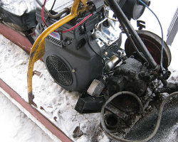
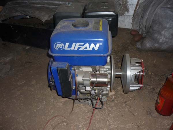
In this publication, we will look at the assembly and installation of a 15 horsepower LIFAN 190 FD four-stroke gasoline engine.
This is a powerful universal engine, which, we note, is suitable not only for installation on snowmobiles, but also on most agricultural equipment. Now we will talk about assembling the engine for the Buran snowmobile, photo:
If you are interested in purchasing an engine of this particular manufacturer or need more detailed information about its characteristics, then you are welcome to the section of our engine catalog.
Also on our website you will find spare parts for the Buran snowmobile.
Self-made snowmobile with your own hands: a photo of the step-by-step assembly of a tracked snowmobile with a Lifan engine.
The author decided to build his own snowmobile and, perhaps, he succeeded, then I bring to your attention a photo of the main stages of making a homemade product.
First of all, the author decided on the engine, it was decided to purchase a 13 hp Lifan 188 FD engine equipped with an electric starter.
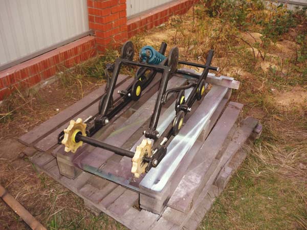
Also, for the construction of a tracked snowmobile, the following were purchased: drive and driven variators, rollers, drive and driven shafts, sprockets.
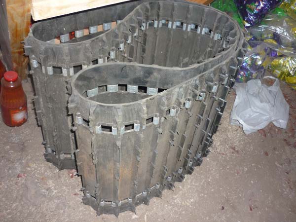
The author used a caterpillar 0.5 meters wide from the "Raida" motor-towing vehicle.
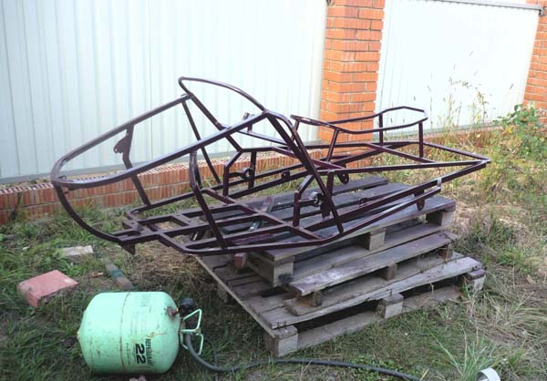
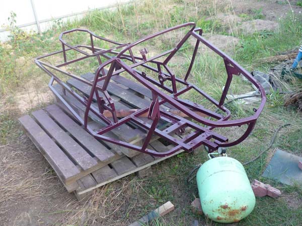
A frame is welded from shaped pipes, parts of the frame were bent on a pipe bender.
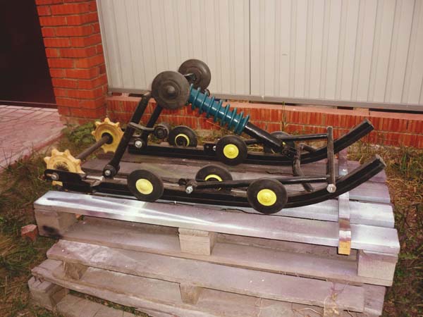
Rollers from the Buran snowmobile, slides from the Tiksi snowmobile.
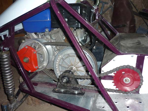
In the photo, the process of installing the driven variator.
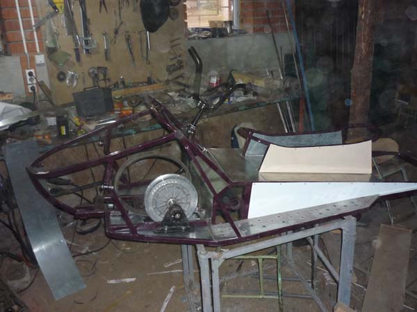
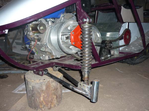
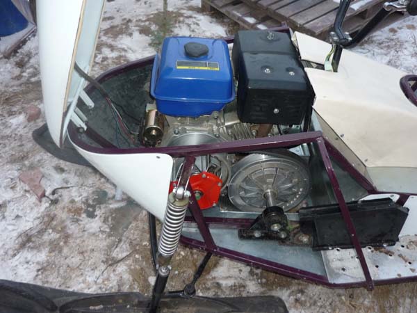
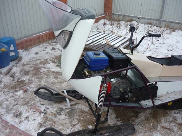
The front suspension is assembled, the engine is mounted on rubber cushions.
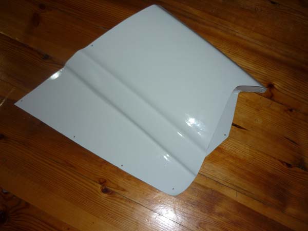
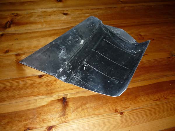
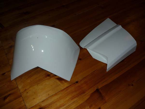
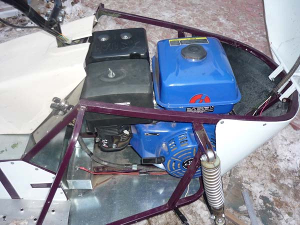
From plastic, the author cut out the lining for the engine compartment.
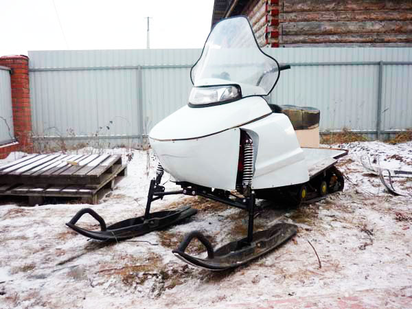
The headlight is borrowed from a scooter, the hood is made from the hood from the VAZ 2110.
The engine is easily accessible.
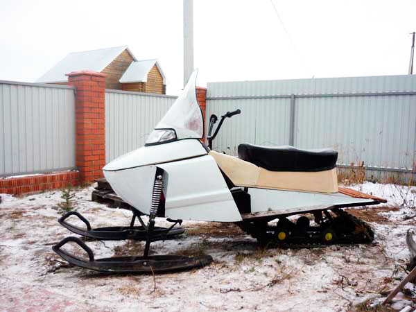
The homemade tracked snowmobile is ready and waiting for some good snow.
After the final revision and painting, the author tested his homemade product.
The author announced the construction budget:
- Engine - 12.5 thousand rubles.
- Variators - 9 thousand rubles
- Caterpillar - 7.5 thousand rubles
- Snowmobile skis - RUB 5,000
- Shafts leading, driven - 2 thousand rubles.
- Rollers, slides - 4 thousand rubles
- Frontal - 1 thousand rubles
- Headlight of a scooter - 450 r.
In addition, turning and welding works were also needed.
I recommend watching the video of the author of the homemade product, where he talks in detail about his snowmobile.


