In detail: do-it-yourself repair of a VAZ 21214 engine injector from a real master for the site my.housecope.com.
Today you will see in the video how you can make a major overhaul of the VAZ 21214 Niva Taiga 1.7 (injector) engine with your own hands. A car with a range of 60 thousand km. Engine 1.7, is power steering. The problem due to which a major overhaul is being carried out, the engine began to tweak. They checked the compression, in one of the cylinders it showed 5. We connected the scanner and saw the errors: P0300 (random / multiple misfires were detected, P0301 misfires were detected in the 1st cylinder. It was in this cylinder that the compression showed a value of 5. At the same time, the check engine light not lit. We measured the output in the first cylinder 15 hectare, in the 4th cylinder 11 hectare.
Video overhaul of the VAZ 21214 Niva Taiga 1.7 engine:
The service life of this engine is in the region of 150 thousand km. run, he passed 65 thousand km. It is impossible to say exactly why the premature repairs were required. If you decide to do everything on your own, this guide will be very useful to you. The whole process is shown from start to finish, with detailed comments.
Before disassembling, clean the engine from dirt.
Using the "17" head, unscrew the three bolts attaching the front axle gearbox bracket to the cylinder block.
Using the "13" head, unscrew the four nuts securing the left support bracket of the power unit to the cylinder block.
... and remove the bracket assembly with the pillow.
After removing the brackets on their mounting pins and threaded holes in the cylinder block, we mount the dismantling stand plate and fix the engine on the stand. Remove the clutch (see here)
| Video (click to play). |
Remove the flywheel and clutch housing cover (see here).
Using the "13" head, unscrew the four nuts securing the bracket for the right support of the power unit to the cylinder block.
... and remove the bracket with the pillow.
Using the "17" head, unscrew the three bolts attaching the generator bracket to the cylinder block.
Using round-nose pliers, we loosen the clamp of attachment to the outlet pipe of the heater radiator of the coolant outlet hose from the throttle assembly (VAZ-21214 engine) or from the carburetor heating unit (VAZ-21213).
We remove the hose from the branch pipe of the outlet tube.
Using the "10" head, unscrew the two nuts securing the flange of the heater radiator outlet pipe to the coolant pump housing.
After unscrewing the nut that secures the tube bracket to the exhaust manifold (see here).
... remove the heater radiator outlet pipe and its sealing gasket.
Using the "13" head, unscrew the three bolts securing the coolant pump to the cylinder block.
... and remove the coolant pump assembly and its gasket.
On an injection engine, dismantle the cylinder head assembly with a receiver, an intake pipe and an exhaust manifold (see here).
On a carburetor engine, remove the cylinder head assembly with the carburetor, intake pipe and exhaust manifold (see here).
Remove the oil separator of the crankcase ventilation system, the oil pan and the oil pump (see the relevant sections).
Using the "10" head, unscrew the six bolts securing the rear crankshaft oil seal holder to the cylinder block.
We pry the rear oil seal holder with a screwdriver for the tides.
... and remove the holder assembly with an oil seal.
From the grooves of the oil seal holder, remove two special bolts (with square heads) securing the clutch housing cover.
Remove the rear oil seal holder gasket.
Remove the camshaft drive cover, dismantle the chain, crankshaft sprocket, oil pump drive shaft, chain tensioner shoe (see the relevant sections).
Using a 10 spanner spanner, unscrew the bolt securing the bracket for the drain pipe of the oil separator of the crankcase ventilation system.
Using the "14" head, unscrew the two nuts securing the connecting rod cover (the piston should be in the BDC).
Knocking on the side surfaces of the lid with a hammer with a plastic striker.
We take out the lower shell of the connecting rod bearing from the cover.
Leaning on the ends of the rods of the connecting rod bolts, we move the lower head of the connecting rod from the connecting rod journal of the crankshaft.
Resting the wooden handle of the hammer on the connector of the lower connecting rod head, push the piston into the cylinder.
... and remove the piston with the connecting rod from the cylinder.
We take out the upper bearing shell from the connecting rod head.
In the same way, we remove the pistons with connecting rods from other cylinders.
We clamp the connecting rod in a vice with soft metal jaw pads.
With your fingers, gently (without applying great effort) unclench the lock of the upper compression ring.
... and remove the upper compression ring.
... lower compression ring.
... two discs of an oil ring.
Remove the oil scraper ring expander.
For removing the piston from the connecting rod.
... pry the piston pin retaining ring with a screwdriver.
... and remove it from the annular groove of the piston.
In the same way, we take out the second retaining ring of the finger.
... we remove it from the hole in the piston.
Remove the piston from the upper connecting rod head.
If some parts of the connecting rod-piston group are not damaged and slightly worn, then they can be used again. Therefore, when disassembling, we mark the parts in order to install them in the old cylinder.
Using the "17" head, unscrew the two bolts securing the crankshaft main bearing cap.
Remove the main bearing cover.
We take out the lower main bearing shell from the cover.
In the same way, remove four more main bearing caps.
We take out the crankshaft from the cylinder block.
We take out persistent half rings from the grooves of the rear support of the cylinder block.
We take out the upper liners of the crankshaft main bearings from the cylinder block supports.
After disassembling the engine, rinse thoroughly with gasoline and clean the parts from carbon deposits to check their technical condition.
To determine cylinder wear.
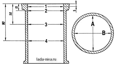
... We measure the cylinder diameter in four belts and two planes (parallel and perpendicular to the crankshaft axis) with an internal gage.
Cylinder measurement scheme: A and B - measurement directions; 1,2, 3 and 4 - belt numbers
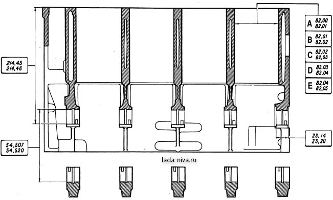
Main dimensions of the cylinder block
To determine the wear of the piston skirt.
... with a micrometer we measure the diameter in a plane perpendicular to the axis of the piston pin, at a distance of 55 mm from the piston crown.
We measure the diameters with a micrometer.
... and main journals of the crankshaft.
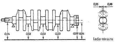
Permissible runout of the main surfaces of the crankshaft
We grind the crankshaft journals to the nearest repair size if their wear or ovality is greater than 0.03 mm, as well as if there are seizures and risks on the journals.
(read also the article "Crankshaft - Grinding or Repair")
After grinding the crankshaft journals.
... it is necessary to remove the plugs of the oil channels.
... Thoroughly rinse the channels to remove abrasive residues and blow with compressed air.
Grinding of the crankshaft journals, removal and installation of new plugs is carried out at the service station.
We assemble the engine in reverse order.
We install new crankshaft bearing shells of nominal or repair size (after grinding the journals).
In the first, second, fourth and fifth bearings of the cylinder block, we install the upper main bearing shells with grooves.
... and in the third support there is a liner without a groove on the inner surface (the same as in the main bearing caps).
Lubricate the main bearing shells with engine oil and put the crankshaft in the supports.
We insert persistent half rings lubricated with engine oil into the grooves of the fifth support.
On the front side of the fifth support, we install a steel-aluminum half-ring, and on the back side - a cermet (yellow).
The surfaces of the semi-rings with an anti-friction coating (grooves are made on them) must face the thrust surfaces of the crankshaft.
We install the main bearing caps in accordance with the marks on their outer surface (counting is carried out from the side of the camshaft drive).
In this case, the locks of the upper and lower shells of each main bearing must be located on one side.
We tighten the bolts of the main bearing caps to the prescribed torque (see here).
Pistons for cylinders are selected by classes.
Marking of the size class of the cylinders on the block
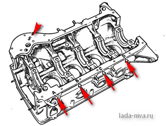
The cylinder diameter class, designated by letters, is stamped on the lower plane of the cylinder block (the plane of the oil pan attachment).
The diameter classes of the piston skirt and the bores for the piston pin are marked on the piston crown.
When installing the piston in the cylinder, the arrow on the piston crown must point towards the camshaft drive.
When assembling the connecting rod-piston group, it is necessary that the piston pin, lubricated with engine oil, enters the hole of the piston or connecting rod with the effort of the hand and does not fall out of them when the finger is vertical.
To check the clearance in the piston ring lock, insert the ring into the cylinder and align the ring with the piston bottom.
Using a set of flat feelers, we check the clearance in the piston ring lock.
Lubricate the grooves on the pistons with engine oil.
We install rings on the pistons.
Install the lower compression ring with the groove ("scraper") down.
If the “TOP” or “TOP” mark is applied to the ring near the lock, then set the ring with the mark up.
The rings should turn freely in the grooves without jamming.
We arrange the rings as follows:
the lock of the upper compression ring is oriented at an angle of 45 ° to the axis of the piston ring;
the lock of the lower compression ring - at an angle of 180 ° to the axis of the lock of the upper ring;
oil scraper ring lock - at an angle of 90 ° to the axis of the upper compression ring lock (the expander joint is located on the side opposite to the lock).
Before installing the ShPG parts, we lubricate the cylinders, pistons with rings and connecting rod bearings with engine oil.
Before installing the piston in the cylinder, we put an adjustable mandrel on the piston.
... and, tightening the mandrel, squeeze the piston rings.
Install the piston with the connecting rod into the cylinder.
Resting the hammer handle on the piston bottom, push it into the cylinder.
When installing the connecting rod cap, the number on the connecting rod and the cap must match and be on one side of the connecting rod.
Tighten the connecting rod nuts with the prescribed torque (see here).
Further assembly is carried out in the reverse order of disassembly.
Replace gaskets and gaskets with new ones.
When installing the flywheel, we orient it so that the mounting (conical hole), located on the rear plane of the flywheel next to the ring gear, is located opposite the connecting rod journal of the fourth cylinder.
Before disassembling, we clean the engine from dirt.
Using the "17" head, unscrew the three bolts attaching the front axle gearbox bracket to the cylinder block.
Using the "13" head, unscrew the four nuts securing the left support bracket of the power unit to the cylinder block.
... and remove the bracket assembly with the pillow.
After removing the brackets on their mounting pins and threaded holes in the cylinder block, we mount the dismantling stand plate and fix the engine on the stand. Remove the clutch (see Replacing the driven and driving clutch discs).
Remove the flywheel and clutch housing cover (see Replacing the rear crankshaft oil seal).
Using the "13" head, we unscrew the four nuts securing the bracket for the right support of the power unit to the cylinder block.
... and remove the bracket with a pillow.
Using the "17" head, unscrew the three bolts attaching the generator bracket to the cylinder block.
Using round-nose pliers, we loosen the clamp of attachment to the outlet pipe of the heater radiator of the coolant outlet hose from the throttle assembly (VAZ-21214 engine) or from the carburetor heating unit (VAZ-21213).
We remove the hose from the branch pipe of the outlet tube.
Using the "10" head, unscrew the two nuts securing the flange of the heater radiator outlet pipe to the coolant pump housing.
... remove the heater radiator outlet pipe and its sealing gasket.
Using the "13" head, unscrew the three bolts securing the coolant pump to the cylinder block.
... and remove the coolant pump assembly and its gasket.
On an injection engine, dismantle the cylinder head assembly with a receiver, an intake pipe and an exhaust manifold (see Removing and disassembling the cylinder head of an injection engine).
On a carburetor engine, we remove the cylinder head assembly with the carburetor, intake pipe and exhaust manifold (see Removing and disassembling the cylinder head of a carburetor engine).
Remove the oil separator of the crankcase ventilation system, the oil pan and the oil pump (see the relevant sections).
Using the "10" head, unscrew the six bolts securing the rear crankshaft oil seal holder to the cylinder block.
We pry the rear oil seal holder with a screwdriver for the tides.
... and remove the holder assembly with an oil seal.
From the grooves of the oil seal holder, remove two special bolts (with square heads) securing the clutch housing cover.
Remove the rear oil seal holder gasket.
Remove the camshaft drive cover, dismantle the chain, crankshaft sprocket, oil pump drive shaft, chain tensioner shoe (see the relevant sections).
Using a 10 spanner spanner, unscrew the bolt securing the bracket for the drain pipe of the oil separator of the crankcase ventilation system.
Using the "14" head, unscrew the two nuts securing the connecting rod cover (the piston should be in the BDC).
Knocking on the side surfaces of the lid with a hammer with a plastic striker.
We take out the lower shell of the connecting rod bearing from the cover.
Leaning on the ends of the rods of the connecting rod bolts, we move the lower head of the connecting rod from the connecting rod journal of the crankshaft.
Resting the wooden handle of the hammer on the connector of the lower connecting rod head, push the piston into the cylinder.
... and remove the piston with the connecting rod from the cylinder.
We take out the upper bearing shell from the connecting rod head.
In the same way, we remove the pistons with connecting rods from other cylinders.
We clamp the connecting rod in a vice with soft metal jaw pads.
With your fingers, gently (without applying great effort) unclench the lock of the upper compression ring.
... and remove the upper compression ring.
... lower compression ring.
... two discs of an oil ring.
Remove the oil scraper ring expander.
For removing the piston from the connecting rod.
... pry the piston pin retaining ring with a screwdriver.
... and remove it from the annular groove of the piston.
In the same way, we take out the second retaining ring of the finger.
By sliding the piston pin.
... we remove it from the hole in the piston.
Remove the piston from the upper connecting rod head.
If some parts of the connecting rod-piston group are not damaged and slightly worn, then they can be used again. Therefore, when disassembling, we mark the parts in order to install them in the old cylinder.
Using the "17" head, unscrew the two bolts securing the crankshaft main bearing cap.
Remove the main bearing cover.
We take out the lower main bearing shell from the cover.
In the same way, remove four more main bearing caps.
We take out the crankshaft from the cylinder block.
We take out persistent half rings from the grooves of the rear support of the cylinder block.
We take out the upper liners of the crankshaft main bearings from the cylinder block supports.
After disassembling the engine, rinse thoroughly with gasoline and clean the parts from carbon deposits to check their technical condition.
To determine cylinder wear.
... We measure the cylinder diameter in four belts and two planes (parallel and perpendicular to the crankshaft axis) with an internal gage.
To determine the wear of the piston skirt.
... with a micrometer we measure the diameter in a plane perpendicular to the axis of the piston pin, at a distance of 55 mm from the piston crown.
We measure the diameters with a micrometer.
... and main journals of the crankshaft.
We grind the crankshaft journals to the nearest repair size if their wear or ovality is greater than 0.03 mm, as well as if there are seizures and risks on the journals.
After grinding the crankshaft journals.
... it is necessary to remove the plugs of the oil channels.
... Thoroughly rinse the channels to remove abrasive residues and blow with compressed air.
Grinding of the crankshaft journals, removal and installation of new plugs is carried out at the service station.
We assemble the engine in reverse order.
We install new crankshaft bearing shells of nominal or repair size (after grinding the journals).
In the first, second, fourth and fifth bearings of the cylinder block, we install the upper main bearing shells with grooves.
... and in the third support there is a liner without a groove on the inner surface (the same as in the main bearing caps).
Lubricate the main bearing shells with engine oil and put the crankshaft in the supports.
We insert persistent half rings lubricated with engine oil into the grooves of the fifth support.
On the front side of the fifth support, we install a steel-aluminum half-ring, and on the back side - a cermet (yellow).
The surfaces of the semi-rings with an anti-friction coating (grooves are made on them) must face the thrust surfaces of the crankshaft.
We install the main bearing caps in accordance with the marks on their outer surface (counting is carried out from the side of the camshaft drive).
In this case, the locks of the upper and lower shells of each main bearing must be located on one side.
Tighten the main bearing cap bolts to the specified torque (see Tightening torques for threaded connections).
Pistons for cylinders are selected by classes.
The cylinder diameter class, designated by letters, is stamped on the lower plane of the cylinder block (the plane of the oil pan attachment).
The diameter classes of the piston skirt and the bores for the piston pin are marked on the piston crown.
When installing the piston in the cylinder, the arrow on the piston crown must point towards the camshaft drive.
When assembling the connecting rod-piston group, it is necessary that the piston pin, lubricated with engine oil, enters the hole of the piston or connecting rod with the effort of the hand and does not fall out of them when the finger is vertical.
To check the clearance in the piston ring lock, insert the ring into the cylinder and align the ring with the piston bottom.
Using a set of flat feelers, we check the clearance in the piston ring lock.
Lubricate the grooves on the pistons with engine oil.
We install rings on the pistons.
Install the lower compression ring with the groove ("scraper") down.
If the “TOP” or “TOP” mark is applied to the ring near the lock, then set the ring with the mark up.
The rings should turn freely in the grooves without jamming.
We arrange the rings as follows:
the lock of the upper compression ring is oriented at an angle of 45 ° to the axis of the piston ring;
the lock of the lower compression ring - at an angle of 180 ° to the axis of the lock of the upper ring;
oil scraper ring lock - at an angle of 90 ° to the axis of the upper compression ring lock (the expander joint is located on the side opposite to the lock).
Before installing the ShPG parts, we lubricate the cylinders, pistons with rings and connecting rod bearings with engine oil.
Before installing the piston in the cylinder, we put an adjustable mandrel on the piston.
... and, tightening the mandrel, squeeze the piston rings.
Install the piston with the connecting rod into the cylinder.
Resting the hammer handle on the piston bottom, push it into the cylinder.
When installing the connecting rod cap, the number on the connecting rod and the cap must match and be on one side of the connecting rod.
Tighten the connecting rod nuts with the prescribed torque (see Tightening torques for threaded connections). Further assembly is carried out in the reverse order of disassembly. Replace gaskets and gaskets with new ones.
When installing the flywheel, we orient it so that the mounting (conical hole), located on the rear plane of the flywheel next to the ring gear, is located opposite the connecting rod journal of the fourth cylinder.
Years of release - (1994 - present)
Cylinder block material - cast iron
Power system - carburetor (21213) / injector (21214)
Type - in-line
Number of cylinders - 4
Valves per cylinder - 2
Piston stroke - 80mm
Cylinder diameter - 82mm
Compression ratio - 9.4
The volume of the Niva 21213 engine is 1690 cc.
Engine power Niva 21213 - 81 hp / 5200 rpm
Torque - 125Nm / 3000 rpm
Fuel - AI93
Fuel consumption - city 11.5l. | track 8.3 l. | mixed 10.5 l / 100 km
Oil consumption - 700 g per 1000 km
Niva engine weight - 117 kg
Overall dimensions of the Niva 21213 engine (LxWxH), mm -
Oil in the Niva 21213 engine:
5W-30
5W-40
10W-40
15W-40
How much oil is in the Niva 21213/21214 engine: 3.75 liters.
When replacing, fill in about 3.5 liters.
Niva engine resource:
1. According to the data of the plant - 80 thousand km
2. In practice - up to 150 thousand km
TUNING
Potential - 200 HP
Without loss of resource - 90 hp.
Engine VAZ 21213 1.7 liters. carburetor / injection (21214) inline 4-cylinder with an overhead camshaft, the Niva timing belt has a chain drive. On the basis of 214 motors, a VAZ 2123 engine is produced for a Chevy Niva, the differences in the adaptation of the unit for installation in the engine compartment of shnivy and attachments of attachments are technically almost identical.
The main differences between the VAZ 21213 engine and 2106 with a cylinder diameter of 82 mm., The cylinder head, the Niva 21213 engine block from 2106 differs in lower height. Of the advantages of 213 motors, it is worth noting the presence of a chain tensioner (no need to tighten) and hydraulic compensators (no need to adjust the valve). Disadvantages of the Niva engine - noisy, eating oil, prone to overheating to vibrations, low resource.
The motor has all the problems of the classic series, all the same, the 21213 niva engine heats up, troit, knocks, etc., what are the problems, for each case, is described in detail HERE, in the section of problems and malfunctions.
It makes no sense to write about this for a long time, because the Niva chip is useless, the atmospheric engine cannot be stirred up with the chip, and all the rave reviews are nothing more than an attempt to justify the waste of money, we go further.
The question on the agenda: how to increase the engine power of the cornfield without any special tweaks? The first stage is to increase the piston stroke to 84 mm using a crankshaft from a VAZ 2130, 82mm pistons with a 2mm displacement of the piston pin and we already have 1.8 liters. The second stage is to bore the cylinders under the 84 mm piston, thus assembling the 1.9 engine on the field. To fully boost the VAZ 21213 engine, you need to add a more efficient carburetor, bore the cylinder head channels (as described in HERE), an inlet diameter of 33 mm and an outlet of 31 mm, it is advisable to use light connecting rods, as a result we get about 100 hp.
The third stage - we are building a 2 liter engine. We buy on the market a tuning crankshaft with a stroke of 88mm and pistons 84mm with a 4mm pin offset. A full-fledged revision of the VAZ 21213 engine will be completed after installing the Nuzhdin camshaft (or equivalent) with a rise of 11.2, a light flywheel, light connecting rods and a modified carburetor, all this in total will give about 110 hp.
- piston of standard diameter, extended stroke
1.8 l. 82x84
85 h.p.
Maximum torque
135Nm at 3000rpm
- a piston with a larger diameter, increased stroke
1.9 l. 84x84
- a piston with a larger diameter, increased stroke
2.0 l. 84x88
Periodically, the forums raise the issue of installing a 2112 motor in a cornfield, this is a rather difficult and meaningless task, due to the fact that 16V motors love revs and are not well suited for an SUV. If you want speed, sell your car and buy a Priora. The Niva is not adapted for high speeds and its tuning should be aimed, first of all, at increasing traction at the bottom.
The pros and cons are described HERE in the Turbo Classic section.
We use kit kits based on the PK-23-1 supercharger or analogs with a pressure of 0.5 bar, injectors from the 406th Volgovskiy engine, the piston remains factory-made, the output is more than 100hp. The resource will be reduced, but not critical.
It is not recommended to install more efficient superchargers, the factory piston will not withstand and the motor will require significant costly changes.
The VAZ 21214 engine was conceived as the first injection engine for a domestic SUV. Niva was not very popular in the USSR, but it was exported to Asia, Great Britain, Europe, Latin America and the USA. Since 1994, there have been several modifications and modifications of the internal combustion engine from Euro-0 to Euro-5 (export).
It is believed that the basis of the ICE 21214 was the previous version 21213. In fact, ¾ parts in the engine
- the engine circuit has changed - an injector instead of a carburetor;
- additional attachments appeared - DPKV, DHX sensor, Bosch MP 7.0 controller;
- a crankshaft with a long crank radius of 40 mm, not used in previous AvtoVAZ engines;
- Cylinder head with holes for the phase sensor and receiver pins, hydraulic supports for valve levers instead of adjusting bolts.
Since the base model bends the valve, the 21214 engine did not escape this fate, therefore, not only a description of the engines was added to the manual, but also a maintenance schedule to ensure at least the minimum declared resource of 80,000 km, which was promised by the manufacturer's representatives.
The design of the 21214 power drive provides it with the following technical characteristics:
combined cycle 10.5 l / 100 km
clutch bolt - 19 - 30 Nm
bearing cover - 68 - 84 Nm (main) and 43 - 53 (connecting rod)
cylinder head - three stages 20 Nm, 69 - 85 Nm + 90 ° + 90 °
With the advent of thermal valve clearance hydraulic compensators, it is recommended to use exclusively high-quality oil in the engine.

