In detail: do-it-yourself repair of an internal combustion engine 2st from a real master for the site my.housecope.com.
1. Use fenders, seat covers and floor mats to protect your vehicle from dirt and damage.
2. When disassembling, place the parts in the correct order to facilitate reassembly.
3. Observe the following rules:
a) Before carrying out work on electrical equipment, disconnect the cable from the negative terminal of the storage battery.
b) If it is necessary to disconnect the battery for control check or repair work, be sure to first disconnect the cable from the negative (-) terminal, which is connected to the car body.
c) When carrying out welding work, disconnect the battery and connectors of the electronic control unit.
4. Check reliability and correctness of fastening of couplings and fittings of hoses and wire connectors.
5. Non-reusable parts.
a) Be sure to replace the split pins, gaskets, o-rings, oil seals, etc. to new ones.
b) Parts that cannot be reused are marked with “•” in the illustrations.
6. Before working in the spray booth, disconnect and remove the battery and the electronic control unit from the vehicle.
7. If necessary, apply a sealing compound to the gaskets to prevent leaks.
8. Carefully observe all technical conditions regarding the values of the tightening torque of the threaded connections. Be sure to use a torque wrench.
| Video (click to play). |
9. Depending on the nature of the repairs being performed, it may be necessary to use special materials and special tools for maintenance and repair.
10. When replacing blown fuses, make sure that the new fuse is rated for the correct amperage.
FORBIDDEN exceed this rated current or insert a fuse with a lower rating.
11. Appropriate precautions must be taken when jacking and supporting the vehicle. It must be ensured that the vehicle is lifted and the supports are installed under it in the places designated for this.
a) If the vehicle is to be jacked up only at the front or rear, it must be ensured that the wheels of the opposite axle are securely locked for safety reasons.
b) Immediately after jacking up the vehicle, it is imperative to place it on stands. It is extremely dangerous to carry out any work on a vehicle that is suspended on only one jack.
1. Remove the air filter.
2. Check and clean the air filter if necessary.
a) Check if the filter is too dirty or oily, and its integrity. Replace if necessary.
b) Blow out the filter element with compressed air (first from the inside and then from the outside).
3. Install the air filter.
Note: check and adjust on a cold engine.
1. Remove the cylinder head cover with gasket.
2. Measure the thermal clearance in the valves.
a) Set the piston of the first cylinder to TDC of the compression stroke. - Turn the crankshaft until the mark on the crankshaft pulley aligns with the indicator on the oil pump housing.
Check that the valve tappets of the first cylinder are free and the fourth cylinder is clamped.
If these conditions are not met,
turn the crankshaft one
b) Adjust the valve clearances marked in the figure.
Measure the clearances of only those valves that are shown in the figure.
- Record measurement results that are out of specification. The measurement data will be required later when choosing the required shims (in my case, the size determined for each washer was “removed” at the factory).
Thermal clearances in valves
(measured on a cold engine):
intake valves. 0.20-0.30mm
exhaust valves. 0.25 - 0.35 mm
5. Adjustment of thermal clearances in the valves.
Note: the valves of one cylinder are controlled at the same time.
a) Turn the crankshaft so that the lug of the intake valve cam of the given cylinder is in a vertical position.
b) Rotate the notches on the pusher adjusting washers so that they can be accessed with a small screwdriver.
c) Depress the valve lifters.
d) Using a small screwdriver and magnetic bar, remove the shims.
e) Measure the thickness of the removed adjusting washer with a micrometer. Calculate the thickness of the new shim so that the design clearance meets the specifications given in the specification:
Select the shim that is closest to the design thickness. Note: Shims are available in 25 sizes, from 2.20 mm to 3.40 mm in 0.05 mm increments. The thickness is stamped on the washer.
e) Remove the special tool.
g) Recheck the valve clearance.
h) If necessary, adjust the clearances in the valves of other cylinders.
6. Install the cylinder head cover.
2- drain pipe fastening nut;
4 - fuel return hose to the tank;
5-sealing washer of the injector nozzle;
6 - nozzle sealing washer;
7 - high pressure fuel lines.
1. Remove the high pressure fuel line clamps. Disconnect fuel lines from injectors and injection pump.
2. Unscrew the nuts securing the drainage pipeline and remove it together with the gaskets.
3. Remove the injectors (use a high tool head) and lay them out in the order of installation on the cylinders.
4. Remove the nozzle and sprayer seals from the head.
1 - fuel supply from injection pump
2 - channel for "return" of excess fuel
The nozzles are checked for general tightness, the tightness of the sprayer, the mobility of the sprayer needle, the pressure of the beginning of the opening of the sprayer needle, the shape of the atomized fuel jet and the presence of gas erosion of the sprayer and other performance indicators. Entrust the check to qualified specialists (here in Blagoveshchensk this is MIRAGE (a very large number of stands for testing engines, high pressure fuel pumps, injectors, etc.) and GRAND MOTORS).
Pressure of the beginning of the rise of the sprayer needle, bar
1. Replace the sprayer only with the one specified by the manufacturer.
2. Tighten the gun mount nut to 37 Nm.
Attention: applying a higher torque will deform the sprayer and damage it.
3. Thoroughly clean the nozzle slots in the block head. Install new sealing washers in the cylinder head seat. Install the injectors, tighten them to a torque of 64 N.m.
Attention: exceeding the tightening torque is not allowed.
4. Install new aluminum (the old system can suck in air) sealing washers of the drainage pipeline and the pipeline itself, tighten the fastening nuts to a torque of 29 N.m. Connect the drain line to the fuel return hose to the tank.
6. Start the engine and check for fuel leaks.
7. Adjust idle speed (if necessary).
Adjust the gear shift in the automatic transmission with a throttle cable (commonly referred to as a KIK-down cable). Many owners of automatic transmissions on a minibus have such a defect. Over time, someone in the heat, someone after passing 80-90 km An automatic transmission, even sometimes with a smooth acceleration out of the blue, throws off OVERDRIVE-and on 3 speed... Sometimes this happens several times that tires the driver and begins to annoy and distract him, periodically forcing him to “play” the accelerator pedal.
Regulator on the high pressure fuel pump (TNVD)
1. Throttle cable going to the automatic transmission 2. fixing the shell with two nuts to the clamp to the high-pressure fuel pump
And the reason lies in a worn out or requiring adjustment of the throttle cable (goes from the regulator of the injection pump to the automatic transmission), which gives information to the automatic transmission about the degree of pressing the pedal. Sometimes the cable “rubbing in” or falling out of the seal in a metal clamp (which leads to a decrease in the length of its free play) and no longer meets the requirements for automatic switching.
The principle of operation is such that when the throttle cable is fully extended, a downshift occurs (for example, from 4th to 3rd, from 3rd to 2nd, from 2nd to 1st). Since the throttle cam opens the oil valve when the cable is fully extended. If you fully extend it, you can go as on the first one - without switching.
We will tell you how to adjust it: Loosen the nuts for fixing the cable sheath (2) and fix it in such a way that the protruding end of the cable is not stretched (it sags a little and is completely pulled out of the sheath only at the position of the maximum regulator speed). We fix and check on the track in high-speed mode. If it is required to weaken even more, we select it experimentally. He performed similar actions on his car, achieved good results, switches back only during long ascents, as well as during intensive overtaking (with black smoke) ...
Supplement to the article sent to us
By changing the length of the throttle position cable, you actually control the oil reducer, which forms the pressure controlling the gearbox. It becomes a kick-down cable only when the gas pedal is fully depressed. By changing the length of the cable, you can set the gearbox operation modes: smoother - economy - by lengthening it, or sharper - sporty - by shortening. On new boxes there are similar switches, and on ours, you should choose the golden mean, otherwise the engine power is not used efficiently. When choosing a high gear, the diesel engine runs at low revs and accelerates very slowly - the diesel engine does not pick up. They keep the revs well, but accelerate slowly. Therefore, the entire set of speed is in low gears, an overdrive for a smooth ride! The problem under discussion is the shifting of the gear when the load increases. The pedal is not fully depressed - this is not a kick-down, therefore, this is the normal reaction of the box to the load. However, it may seem abnormal if there is any problem with the oil.
1.Low oil level - the pump traps air along with the oil and the resulting emulsion does not have the required compression properties, and the valve mechanism considers that there is a large overload and downshifts.
2. High level - the rims of the gears of the box cling to the oil and foaming it, the effect is the same.
3. Clogged oil filter - oil does not enter the pump - the pump is catching air - see above. An additional symptom is a sharp rise in the oil level on the dipstick. Those. start the car, measure the oil level and drive. When the effect of resetting the gears appears, they are measured again. Typically, the measured level is well above the heated oil level.The car stood at idle speed, the level is measured again and it drops to the normal level of heated oil!
Probably, there are also external faults. But they are all diagnosed as low pressure in the main oil line.
Our boxes, in principle, are considered indestructible, so you can try to rinse the filter and enjoy driving a new car. The only problem is the accuracy of the assembly. the oil tubes in the pan sit tight, but nowhere is it written. And once removed, it slips back into place - but doesn't hold the pressure! It is necessary to expand them by ten and install them tightly in place.
Overheating of the oil is also possible. When in July the temperature in Moscow exceeded +30, the car did not drive over 110 by any means. The oil cooler is clean outside, I don’t know inside - laziness. but as the temperature dropped to +25 everything is OK.
Fig. 1 Arrows indicate the places of possible labeling.
If damage occurs in the head of the block or the metal gasket between the cylinder block and the head (often due to overheating), it is not necessary to dismantle the entire engine to disassemble the upper part, since everything can be done in place. In order not to short-circuit anything accidentally (especially when dismantling the generator), Disconnect the battery terminal before starting work! We drain the coolant from the system. Before starting work, it is advisable to stock up on boxes in order to put fasteners there from the parsing of each individual device (unit).
To do this, we need to remove the top of the seat, covers with levers, remove the cables, remove the fan casing, viscous coupling, the filler neck of the coolant system with double pipes assembled is better to unscrew behind the temperature sensors at the entrance to the block head (3 nuts by 12).
It will be necessary to loosen and remove the generator drive belts, the power steering belt can be left alone, since we do not need the lower part of the engine (unless we want to change the timing belt and the bypass roller).
We remove the generator with a vacuum pump so that dust and dirt does not get into, we put bags on the ends of the hoses, we will take care of the copper washers at the top and bottom of the fittings immediately when unscrewing the lines (it is advisable to have new ones, but you can burn copper ones). Remove the timing belt cover, unscrew 6 different (both in length and head number) bolts on the fan cover, remove the cover.
Rotate the crankshaft with the 19 head clockwise so that the TDC marks are exposed (the mark on the camshaft pulley is under the upper cut of the block head and the mark on the rim of the injection pump pulley with a mark on the cover under it), we take a real marker (hard to erase and clearly visible - white) and mark the camshaft pulley and injection pump pulley at three points (as shown in Figure 1). On the lower casing and the integral pulley of the drive belts on the crankshaft, we also apply a couple of marks for their convenient alignment later (although if we do not touch the crankshaft, it will remain intact throughout the entire process of work). Now we unscrew the tension roller, remove the spring and bend the belt gently down, pulling it a little, and fix it. If the engine model is equipped with an automatic heating device for the injection pump with coolant supply from the head union, disconnect the branch pipe by loosening the clamp.
Next, we disconnect the electrical part, before unscrewing it is advisable to spray all the elements of the WD 40 fastener, remove the wires from the additional resistor or insulator, unscrew the jumper on the glow plug bus, remove the protective caps and nuts by 10 each,
we release the aluminum conductor. Disconnect the wire from the temperature sensor (to display the engine temperature on the instrument panel). Then, after removing the bar for securing 4 fuel pipes on the intake manifold with a mass wire (nuts for 10), unscrew the fuel line clamps at the injectors with a good 17 open-end wrench and, in turn, - the terminals on the fuel pump (removal procedure - 1 cylinder, 2 cylinder , 3 and 4, respectively, to assemble - in the reverse order for the convenience of tightening the fuel line clamps on the injection pump - first the lower ones, and then the upper ones). Pulling off the hose going to the OUT bolt in the injection pump,
unscrew the "return" line to unscrew the nuts on top of the "return" without breaking it, sprinkle it with kerosene or WD 40 a little.If the nut is stuck with us and tries to unscrew together with the nozzle (while trying to fix the nozzle body from the bottom under the intake manifold from scrolling, it is difficult, but possible, by tapping the "return" with a copper bar next to the stuck nut). Next, you can unscrew the nozzles and glow plugs themselves and remove them away, taking the injectors for inspection and adjustment, and connect the glow plugs in parallel and apply a voltage of 12 volts to them for 4-5 seconds until they warm up to red (assessing the uniformity of glow of the tips of the candles and simultaneity) ...
The next step will be to unscrew 4 nuts by 14 from the exhaust manifold studs (the air ducts are disconnected and the heat reflectors from the exhaust manifold have been removed), thereby freeing the turbine. It will be easier to do this with a spanner with a ratchet (there is very little space).
We unscrew the nuts with rubberized washers at the valve cover, remove the valve cover. Now you can start actually dismantling the cylinder head. But do not rush, you need to loosen the bolts by 14 carefully in a certain sequence so that it does not bend like a "house".
Having unscrewed, we immediately remove the head with the intake and exhaust manifolds, while the metal gasket can slide off the studs of the outlet flange (when undocking the parts of the exhaust manifold).
We inspect the gasket under the head, the surface of the pistons and the surface of the head adjacent to them, we determine the causes of our troubles (cracks between the valves, gasket breakdown, cracks in the prechambers, etc.).
The assembly is carried out in the reverse order, we first clean the entire surface of the block from scale and other contaminants, it is advisable to check it on a plane too.
We put the gasket, make sure that the guides (inserted into the cylinder block) are in place and that the gasket is well on them and clearly coincides with the holes. On top we put the assembled head with the collectors installed (do not forget, after repairing the head and assembling it, make sure that the cam pulley is tightened with a torque of 88NM, and put it in a position where the risks are combined on the camshaft pulley along the upper cut of the head, otherwise, with other valve positions, the head will simply not sit in place). We make sure that the four pins with a metal gasket on them enter the holes in the intake flange of the turbocharger.
We lower it slowly, holding the block head, making sure that it sits neatly and tightly on the guide bushings. We tighten the block head in several steps, first in the agreed sequence, using a torque wrench, tighten with a torque of 44-45 Nm, then mark the position of the bolts with a white marker, apply risks from the center of the bolt head to the engine front. Then we turn the bolts 90 degrees in the same sequence, letting the head stand, continue broaching, turn the bolts another 90 degrees, as a result, the risks on the bolts should look at the back of the engine, and the torque will reach 100-110 NM. As for the questions, is it worth it, after the engine has passed 500-1000 km, to stretch the head again, everyone decides for himself, depending on the material from which the gasket is made and other conditions, but pressed in the way presented above, the head in an additional should not need a broach.
Let's see if we have lost the position of the crankshaft. Using a 17 key, hold the injection pump pulley in such a position so that the marks made by us with a white marker before removing the timing belt are aligned without any problems, while holding the injection pump pulley we hook the belt and the camshaft pulley (also in accordance with the white marks on the belt and pulley), free play select the tensioner roller with the spring installed, once again provide the timing belt tension and fix the tensioner bolt with a torque of 37NM.We will check the correctness of the timing belt installation by rotating the crankshaft bolt clockwise to make sure that nothing is sticking and the valves do not meet with the pistons, and the marks do not go anywhere and are set correctly (whatever you say).
1. Temperature sensor (for display on the instrument panel);
2. additional resistor of the second stage of incandescence;
3. coolant outlet from the block head for connecting the heating machine to the high-pressure fuel pump;
4. Studs to adapter flange from exhaust manifold to turbine.
We fasten the exhaust manifold to the head with a moment 47NM, tighten the intake manifold with bolts to a torque of 18NM.
This is how an already extended cylinder head looks like (the marks on the bolt heads are facing back). The numbers indicate the sequence of tightening the bolts in a criss-cross pattern from the center to the edges (if you feel that during broaching some bolt stretches and begins to go easier, unscrew it immediately and replace it with a new bolt).
The belt itself, preferably the original one, should stand so that the markings on it are readable when viewed from the back of the engine. First, we put it on the camshaft pulley, then, holding the key on the high pressure pump pulley bolt, we pass through it (there should not be any slack, even though the high pressure fuel pump does not like it in this position, it tries to slip off, hold it), then we pass the reverse side of the belt pump and get on the crankshaft gear, so that the marks are aligned too (a notch on the oil pump cover with a dot on the crankshaft timing gear skirt, see the picture below), and then we drive it along the bypass roller, without releasing it, in tension. We bring the entire free movement of the belt to the spring-loaded roller, which regulates the tension of the belt. We check the tension and fix the roller.
If the belt has not been removed, you can correctly set the mark on the crankshaft timing gear, covered by a casing, by focusing on the needle on the oil pump housing cover and the notch on the crankshaft pulley rim (provided that the veneer groove on the pulley has not been re-sharpened!).
We assemble the covers, casings, a generator with a vacuum pump, fasten the manifold flange to the turbine (4 nuts by 14), install the belts. The nozzles must be tightened with a torque of 64NM, take care in advance of the aluminum washers (4 pieces) with holes for the return flow, 4 flame-reflecting tubular washers (for crushing under the nozzles), bronze washers under the nozzle itself (if not much damaged, you can reuse it). We install the "return" line, on top of it we tighten the nuts with a torque 29NM... We tighten the glow plugs to a torque of 13NM.
With injectors, there is also a problem with a clogged return channel in them, usually after assembling the engine, I do not install the return pipe, I pump the injection pump and fill the tubes to the terminals at the injectors and start the engine. By the way diesel droplets fly from the return channel of each nozzle, one can judge about the passage of excess fuel from the nozzle “return” channel into the metal line for collecting and removing excess diesel fuel. The injector, from where the excess fuel does not fly, requires cleaning and adjustment.
Engine shaking can also be caused by torn engine mountings or automatic transmissions (manual transmissions).
It is possible to determine which injector does not work at all on a working engine, sequentially giving a terminal block to each injector to find one for which the engine operation will practically not change, but this method can only find a completely jammed injector. You need to act carefully, because there is a glow plug bus nearby (which at the time of startup, and then continues to hold voltage for some time) and you can short it, which will lead to arcing and failure of the fuse in the power unit with a nominal value of 80 Amperes. But to find the nozzle that pours, or does not have a clear cutoff, normal spray, clogged with channels on the "return" - it is more difficult, you need to check them and, possibly, bulkhead and adjustment at the stand.
It may be necessary to adjust the idle speed, the gas pedal cable.Assemble the covers and fit the seats and test the partially remanufactured engine with a new head (contracted or remanufactured) in a test drive.
Sponsored links. Shown only to unregistered users
If the stove is cold, of course, there is an air plug. You fill the system, of course, the stove tap is open, you turn off gas, that is. pump you create pressure in the system. You touch the suitable pipes to the stove, as a rule, the upper one heats up a little earlier, the input. As the lower output began to warm up, heat should definitely come from the stove. Further, if there is overheating, see the cylinder head. These engines have a problem - cracks between valve seats. How many did not remove the cylinder head were all. I'm not afraid, people just do not understand that a diesel engine does not like revolutions of more than 3000. 2st, 2LT. And yet, when replacing the thermostat, it must be put with the hole up, especially for the correct filling of the system with antifreeze.
In the previous article, I provided information about weak spots and the disadvantages of the 1C diesel engine. The next generation of engines 2C from Toyota Motor Corporation, it would seem, on the contrary, should be of better quality, because the experience of the corporation and scientific and technological progress are constantly evolving. But unfortunately, nothing good can be said about diesel engines of the 2C line in comparison with 1C, but there are more drawbacks. Car Models Toyota in which these engines with a volume of 2L are installed are listed below:
- Kaldina CT190 / 196/198 from 1992 to 1998, 2C-I4, 2C-TI4;
- Karina CT150 from 1984 to 1988, 2C-T4;
- Karina CT170 / 176 from 1988 to 1992, 2C-I4;
- Karina CT190 / 195 from 1992 to 1996, 2C-I4;
- Karina 2 CT150 from 1983 to 1987, 2C-I4;
- Karina 2 CT170 from 1987 to 1992, 2C-I4;
- Karina E CT190 from 1992 to 1996, 2C-L-I4, 2C-II-I4;
- Crown CT150 1983 to 1987, 2C-II-I4, 2C-L-I4, 2C-I4, 2C-T-I4;
- Crown CT170 / 176/177 from 1987 to 1992, 2C-L-I4, 2C-I4, 2C-T-I4;
- Crown CT190 / 195 from 1992 to 1996, 2C-II-I4, 2C-L-I4,2C-T-I4;
- Litays / Town Ice CM26 from 1985 to 1986, 2C-I4, 2C-T-I4-T;
- Litays CM0 / 31/36/41 from 1985 to 1992, 2C-I4, 2C-T-I4-T;
- Litays / Town Ice CM51 / 52/55/60/61/65 from 1989 to 1999, 2C-I4, 2C-T-I4-T;
- Litays / Town Ice CP21 / 27/28/36 from 1984 to 1996, 2C-I4, 2C-T-I4-T;
- Litays / Town Ice CP41 / 51 from 1996 to 1989, 2C-I4, 2C-T-I4-T;
- Sprinter CE95 from 1989 to 1991, 2C;
- Sprinter CE100 / 104/106/108/109 from 1991 to 1998, 2C;
- Sprinter CE110 / 114 from 1995 to 1998, 2C;
- Avensis CT220 from 1997 to 2000, 2C-TE;
- Carolla CE110 from 1995 to 2001, 2C-E.
All the weak points and limitations engine 1C inherited 2C and additionally (see below).
- Loss of compression in two cylinders, in most cases in 3 and 4 cylinders;
- Rapid wear of 2C and 2C-T engines installed on minibuses;
- Lack of services for adjustment and the problem with parts for the injection pump with electronics in the event of its repair in 2C-E, 2C-TE engines.
Loss of compression in two cylinders, in most cases in 3 and 4 cylinders
Loss of compression, as a rule, in problematic 3 and 4 cylinders of engines occurs due to leaks in the air pipes connecting the air filter with the turbine and with the air manifold. Dust penetrates through leaky places and mixes with oil and comes with oil to the surface of rubbing parts, grinds them down and quickly renders them unusable. For this reason, the cylinder-piston group and the intake valve plates quickly fail. Accordingly, the wear of the valve discs increases the thermal clearances, and the compression disappears.
Rapid wear of 2C and 2C-T engines installed on minibuses
To put it simply, these motors are not designed for vans, because they are much heavier and larger in size, which increases the load on the engines. On engines with electronically controlled injection pumps, this problem is absent.
Lack of services for adjustment and the problem with parts for the injection pump with electronics in the event of its repair in 2C-E, 2C-TE engines
Of course, the electronically controlled injection pump has benefited the engines:
- reduced fuel consumption;
- reduction of toxic emissions;
- increased uniformity of engine operation;
- motors are quiet.
But the disadvantage is that very rarely there are services that are capable of diagnosing, adjusting such high-pressure fuel pumps in accordance with the modes and parameters set by the designers. The difficulty is that there are no specialists of this level of training, as well as spare parts and technological equipment for the required work.
P.S. Dear Toyota owners with 2C engines! You can comment on the weaknesses and shortcomings identified by you in your personal practice when operating cars.
To tell the truth, motors 2C and 2C-T can deservedly be called a word starting with the letter G. Quality is no one disorder ... The problem, as I understood not only for me, but for all diesel operators, is the outlet of gases to the radiator and expansion tank. The reason is hidden in weak partitions on the motor head, as a result of a slight overheating of the engine, microcracks appear, which are very difficult to find, as a result, the engine is repaired. And it's better not to come up with repairs and put 3C and forget about all the problems - this is a already passed stage.
I disagree. When overheated, microcracks will appear in any engine. It is necessary to monitor the cooling system. If all systems are in good working order, the engine looks like a long time. For example, I have Kaldin for 2C, 400 thousand km without major repairs, I decided to measure the compression in the cylinders, everywhere at 32-33, so you can forget about the capital for now.
Any engine can be ruined. You need to monitor him carefully and he will not let you down. Great engine.
Can you please tell me if the 2c engine will fit the Lit Ice mini truck?
First of all, for a high-quality overhaul of the engine, an experienced and knowledgeable mechanic is needed. After all, overhaul, unlike current repairs, requires much more knowledge and skills.
The most common reason for this costly operation is severe engine wear. As a rule, this happens after a long run or due to improper operation, usually an untimely oil change or a violation of the temperature regime. But there may be other reasons when an engine capital is needed. The so-called water hammer, when an abruptly large amount of liquid enters the air intake system or mechanical damage as a result of an accident.
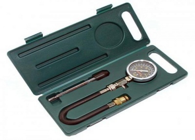
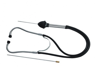
In the process of checking the condition of the motor, a special device is used - a compression meter. Also, a professional mechanic uses a special model of a stethoscope. The compressor is inserted into the plug hole, the ignition module is turned off and the starter turns on each cylinder several times until the maximum value is obtained. The normal value is from 8.5 MPa.
Overhaul of the engine affects almost all engine components. Here is a list of engine overhaul parts:
- repair half rings;
- 7 large and 5 small. clamps;
- set of spark plugs;
- vacuum hose;
- main and connecting rod bearings p 1 set;
- a set of pistons and fingers;
- set of rings;
- a complete set of valves;
- valve guide kit;
- valve seals (valve stem seals) for all valves;
- engine oil seals 3 pieces;
- gaskets 3 pcs. (block head, pallet and valve cover);
- oil filter;
- 6 liters of mineral oil for the engine (m6);
- gear oil for the check point (4 l.);
- for valve cover 2 rubber grommets;
- set of block head bolts;
- a complete set of paper spacers;
- oil pump with intake;
- 10 liters of antifreeze;
- air filter;
- timing belt;
- generator belt;
- breather pipe;
- special clamp for the muffler.
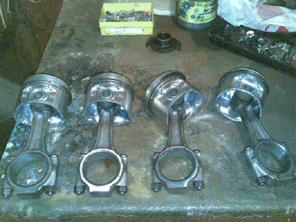
The list of spare parts is quite long, but it directly depends on the amount of future work. At the cost of spare parts, you can never say something unequivocally. It all depends on the manufacturer, and on the shopping center or auto shop.
This amount of work on the overhaul of the engine requires so many spare parts:
- removing the engine;
- engine wash;
- disassembly of the engine;
- flaw detection of engine parts;
- repair of the cylinder head;
- boring and honing of the cylinder block;
- replacement of oil pump drive shaft liners;
- crankshaft grinding;
- crankshaft polishing;
- removing and installing plugs, cleaning the crankshaft channels;
- replacement of the input shaft bearing;
- grinding the surface for the crankshaft oil seal;
- repressing of pistons;
- engine assembly;
- engine installation.
All this also requires a huge number of tools. The mechanic locksmith uses almost all of his arsenal. Not only a standard set of wrenches, but also special tools, pullers, grips, drifts and other tricks.
A separate item is the engine running-in after overhaul. This is a separate and very important process worthy of special consideration.
How much an engine overhaul costs depends, as already mentioned, on many factors. This is the region where the work will be carried out, and the cost of parts, and the contractual potential of the car owner. But in general, you can focus on the figure of 20-30,000 rubles for a 16-valve VAZ engine.
You need to know that even after being sent for repairs, some additional difficulties may arise in the process of work. Not a single master, with any diagnostics, will determine the degree of wear of the cylinder liner walls. The basic version takes into account the work on the cylinder bore for the new piston. However, after disassembly, direct inspection may indicate the need for replacement of the cylinder liners themselves. In this case, you will have to buy a set of cylinders and repress them. It's the same with the engine crankshaft. A complete and reliable wear pattern will only be shown by complete disassembly.
It is worth noting that this replacement of work will not greatly affect the total cost.
In case of mechanical damage to the cylinder block itself or its head, the master will send the part for argon welding processing. This is welding of cracks, chips, faults. The head may be deformed and will have to be sanded. But all this, as they say, will only show an autopsy.
It is recommended when carrying out overhaul work, to defect and, if necessary, replace the clutch parts. Defect the gearbox and change the oil in it. This is very convenient when the engine is completely removed.
The repair is over. Now the engine is cold running. At different repair stations, it is made in different ways. The best option, however, is a bench run-in. The removed engine is installed on a special stand, the oil is poured at the rate and turning on the stand, they begin to rotate at a given speed. However, it is quite difficult to find a stand now. Most often, only at large service centers with exorbitant prices. Small service stations also get out of the situation. There are homemade devices from an electric motor from a 220V network, a reduction gear and attachments for the crankshaft pulley bolt. This system handles cold break-in just as well. The advantage of this device is that it can be used on an already installed engine that is not connected to the power supply and ignition system.
Both cold and hot running-in must be carried out with mineral oil. This is a prerequisite. Only mineral oil will provide a high-quality lapping of parts.
A cold run-in lasts approximately 15 minutes. After that, the master looks at the condition of the oil with a dipstick and sometimes removes the valve cover for control. Then it starts up for another 25-30 minutes. That's it, now the engine can be fully connected to the car system.
After the cold break-in and engine start-up check, the hot break-in period begins. It consists in operating the machine in a gentle way. That is, it is advisable not to overclock the engine over 5000 rpm, not to load the car with excessive weight and not to heat up too much. Otherwise, operate as usual. This mode must be kept 3500 kilometers. After that, you need to drain the used oil. It is advisable to fill in the flush, and run at idle for several minutes. Drain the flush. Now you can fill in fresh.
From that moment on, the usual semisynthetics are poured. The break-in period is over and you can use the machine as usual. Only then can we say that the overhaul has been successfully completed. Below is a helpful informational video:
| Video (click to play). |


