In detail: do-it-yourself heating pad repair from a real master for the site my.housecope.com.
The electric blanket does not turn on, does not work. Electric blanket repair
Video Electric blanket. Unpretentious repair of an electric blanket. channel CompGreece | Repair of computers, gadgets
The utility model relates both to the satisfaction of human life needs and to electrical engineering and can be used to protect household electric heating devices from overheating when a malfunction occurs in these devices, in particular a heating pad. The utility model solves the problem of ensuring the operational reliability of the heating pad by protecting the heating element from overheating with increased fire safety and electrical safety during the entire service life of the electric heating device. The technical result is achieved by the fact that in a heating pad containing a heating element enclosed in a flexible sheath, a protective shutdown device for the heating pad from overheating in the form of an irreversible normally closed fuse connected in series with the heating element and an operating mode switch, a thyristor and a capacitor connected in parallel are introduced into the protective shutdown device the terminals of the heating element, and the irreversible normally closed fuse is made in the form of a current fuse.
| Video (click to play). |
The utility model relates both to the satisfaction of human life needs and to electrical engineering and can be used to protect household electric heating devices from overheating when a malfunction occurs in these devices, in particular a heating pad.
Known flexible electric heater (RF patent
The closest to the claimed utility model is a household electric heater (RF patent


However, the disadvantage of this design is the insufficient electrical safety of the device due to the fact that it does not protect the network from a short circuit in the heating element and in the connecting wires, which is especially important to ensure the durability of the device, since the insulation of the wires and the heating element at high temperatures at the end of its service life, it ages and collapses.
To prevent fire from misuse, the following measures are applied: timer limits the warm-up time; the total power decreases; thermal sensors and thermal relays are installed, temperature controllers are installed in the mode switches, fasteners are made to fix the electric heater on a person or on a bed. But as practice has shown, people leave electric heaters unattended, neglect operating instructions.
The utility model solves the problem of ensuring the operational reliability of the heating pad by protecting the heating element from overheating with increased fire safety and electrical safety during the entire service life of the electric heating device.
The technical result is achieved by the fact that in a heating pad containing a heating element enclosed in a flexible sheath, a protective shutdown device for the heating pad from overheating in the form of an irreversible normally closed fuse connected in series with the heating element and an operating mode switch, a thyristor and a capacitor connected in parallel are introduced into the protective shutdown device the terminals of the heating element, and the irreversible normally closed fuse is made in the form of a current fuse.
Figure 1 shows a General view of a heating pad;
figure 2 shows a functional diagram of a heating pad;
figure 3 - the design of the heating element.
Heating pad contains a heating element 1, a protective shutdown device 2 for an electric heating pad from overheating and a switch 3 for operating modes.
Heating element 1 is designed to heat a heating pad not higher than 60 ° C and is a thermal cable enclosed in a flexible sheath 4, containing a copper current-carrying conductor 5, covered with an insulating layer 6 on top of which a heating coil 7 of nichrome wire is wound, enclosed on top in elastic insulation 8. Heating element 1 is included in the temperature control circuit, and its temperature is maintained in a given mode.
The device 2 of the protective shutdown of the heating pad is designed to protect the heating element from overheating.
Device 2 operates only in combination with thermal cable 1. Thermal cable 1 is used as a sensor for exceeding the limit temperature, i.e. generates a signal for device 2, and device 2 is used as an actuator.
The residual current device 2 contains an irreversible normally closed fuse 9, a thyristor 10 and a capacitor 11.
The irreversible normally closed fuse 9 is an overcurrent fuse with a rated value of the protective operation current, approximately equal to the rated current through the heating element 1.
Fuse 9 is connected with one terminal to the power source through the switch 3 of operating modes, the other to the first terminals of the heating element 1, thyristor 10 and capacitor 11.
Current irreversible fuse 9 is designed to break the power supply circuit of the heating element 1 when the current through it increases above the permissible value.
Thyristor 10 and capacitor 11 are connected in parallel to the terminals of the heating element 1.
The switch 3 of the operating modes of the heating pad is connected in series with the current fuse 9.
Switch 3 switches the operating modes of the heating pad. In one of the modes UPete= Uthe network (where UPete - supply voltage supplied to the heating element of the heating pad, Uthe network - mains voltage), the heating pad is operating at full power. In other mode UPete= 1 / 2U the network (where UPete - supply voltage supplied to the heating element of the heating pad, Uthe network - mains voltage), the mains voltage passes through diode 12, which does not pass the upper half-wave of the mains voltage, the heating pad operates at 50% power.
The heating pad works as follows.
During normal operation, the temperature of the heating element 1 does not exceed the set limit temperature.
When the heating pad overheats, the insulating layer 6 of the thermal cable 1 melts, as a result of which the heating coil 7 is connected to the copper current-carrying conductor 5. Further, the mains voltage pulse through the copper current-carrying conductor 5 is fed to the protective shutdown device 2.
Since the heating coil 7 and the copper current-carrying conductor 5 will be connected (in case of overheating), a mains voltage pulse will appear on the copper current-carrying conductor 5.The mains voltage pulse received on the device 2 affects the control electrode of the thyristor 10 and this leads to the detachment of the thyristor 10, that is, the transition from a non-conducting state to a conducting one. When the thyristor 10 switches to the conducting state, an additional current flows through it. As a result, the current through the irreversible fuse 9 will exceed the maximum permissible value of the current through the fuse 9 and the latter will melt by current and break the power supply circuit of the heating element 1. To prevent the thyristor 10 from going into a conducting state when the supply voltage is applied, capacitor 11 is used.
Thus, the proposed utility model has the following advantages:
- overheating control is carried out over the entire area of the heating pad;
- the absence of contacts in an irreversible fuse, through which a significant current of the heating element flows, and the use of a current fuse as an irreversible fuse significantly increases the durability of the device;
- the introduction of a current fuse instead of a thermal fuse simplifies the device due to the absence of a heating element and the absence of thermal connection with the heating element, increases its reliability and durability by facilitating the operating mode of an irreversible fuse, which is located not in a compartment with a high temperature of 250-300 ° C, but in a place with a normal room temperature of 25-30 ° C.
- the introduction of a current fuse simultaneously with thermal protection provides protection of the power supply network against short-circuit (short circuit) in the heating element and in the connecting wires, which is especially important to ensure the durability of the device, since the insulation of the wires and the heating element, which are at a high temperature by the end of their service life aging and decaying;
- the absence of break contacts in the device, during switching of which noise appears in the electrical network, moreover, the contacts have a very short service life.
An electric heating pad containing a heating element enclosed in a flexible shell, a protective shutdown device for an electric heating pad from overheating in the form of an irreversible normally closed fuse connected in series with the heating element, and an operating mode switch, characterized in that a thyristor and a capacitor connected in parallel are introduced into the protective shutdown device the output of the heating element, and the irreversible normally closed fuse is made in the form of a current fuse.
Hello.
Help me please.
The heating pad is broken.
No identification marks were found on it.
Tell me, please, can it be repaired? I disassembled it, I didn't understand anything. The wires fit the fabric and that's it, no conductive paths, etc.
Let me answer:
In the diagram on the second page - C2 is charging slowly through R29. as soon as he succeeds, the comparator blocks the thermostat. on power off - the capacitor quickly discharges through D15.
According to your task - look for a large timing capacitor and a resistor through which it is charged. and then dismiss one of them.
JLCPCB is the largest PCB prototype factory in China. For more than 200,000 customers worldwide, we place over 8,000 online orders for prototypes and small batches of printed circuit boards every day!
Anything in here will be replaced on browsers that support the canvas element
Winter came imperceptibly, I felt it when on the way to the store my hands were very cold. Of course I know about gloves, but they do not warm, but only keep the warmth of our hands. So I decided to whip up a mini heating pad especially for my precious hands. There are a lot of hot water bottles of this kind in the markets, but still he wanted to make his own.
On sale there are heating pads with a combustible mixture inside, these are camping heating pads with a long reserve on the principle of catalytic combustion.There are also electric heating pads with a built-in battery and a heating element.
A long time ago I bought several power banks with a metal case, and a heating pad was assembled on the basis of this case.
My heating pad will be electric.
On aliexpress, I bought an infrared heating element, which is used as a heater for a warm floor, they are also wrapped around water pipes so that the water in the latter does not freeze. Well, in general, there are a lot of areas of application for such a heater.
The heater consists of two parts - a fiber resistive material that is actually heated, and a heat-resistant flexible insulation.
Such heaters are powered from the mains, 10 meters of such a wire consumes about 160 watts when powered from a 220 volt network. It was this material that I decided to use in my heating pad.
Empirically, I selected the optimal power of the heating element; for this, a nichrome heater was used. I wound the wire on the aluminum frame of the power bank and selected the length so that when powered from 12 and volts, the case heats up to 50 degrees in a maximum of 20-30 seconds, as a result, I found out that this requires a heater with a power of about 6 watts.
Knowing some initial data and Ohm's law, you can easily calculate the required length of the heater, but you need to take into account the fact that as the heater heats up, the resistance of the heater will increase, therefore the power will decrease, the length and resistance for my case is not so important, since everyone will calculate the heater individually depending on supply voltage and heater length.
The heater will be powered by just one standard lithium can 18650, but not directly, but through a step-up converter, it is possible without it, but in order to get the required power from 3.7 Volts, you need to shorten the length of the wire and connect several in parallel. To avoid the collective farm, I decided to use the converter, in this case the heater will be one-piece and will stretch along the entire length of the sleeve, thereby ensuring uniform heating.
In the heating pad, the battery must be protected, otherwise it may fail due to a deep discharge.
I kept some distance between the turns of the heater, having received something like grooves for fingers, so that the heating pad fits perfectly in the hand.
A cheap MT3608 scarf is ideal as a boost converter, we supply 3.7 Volts to the board input and turn the trimmer resistor at the output of the module to 12 Volts. My case turned out to be too small and the converter board simply did not fit, but did not want to change the case, in the end I decided to modify the inverter shawl with wire cutters, and that's what happened.
The size has decreased by two and a half times.
We will make measurements of power and operating time. We supply a voltage of 3.7 volts to the input of the inverter, simulating a battery, connect a heater and a wattmeter to the output of the inverter.
The battery consumption is slightly less than two amperes, of which about 100mA is consumed by the wattmeter itself, which is a little more than 7 watts at the input, and at the output we have 4.5-5 watts, the efficiency is about 70%. Naturally, without an inverter, there would be less losses. But even taking into account all this, a 2200mA / h battery will last for a little over an hour of continuous operation of the heating pad, and if this is not enough, you can take a 3400mA / h battery.
Heat-resistant adhesive tape is wound on the aluminum case of the power bank, in principle it is not needed, initially it was used for thermal insulation of the case. This is necessary so that the battery does not overheat, but later tests showed that most of the heat will be directly transferred to the hand, and the temperature inside the case is not critical.
Despite the cut-down converter board, I had to lengthen the case, since I completely forgot that at the beginning I was planning to shove the charging system here from the USB.
The heating pad is turned on with a button without fixing.
The button is located directly under the thumb, it is convenient, regardless of which hand you have a heating pad in.The button here is not easy to use, since the heating pad will mostly be in your pocket, then there is no guarantee that you will not leave it on, and there will be no such problems with the button, let go and everything turned off.
The charging circuit is based on TP4056, nothing new. This fee also had to be reduced.
Well, now we turn on the heating pad and measure the temperature.
I think the result is excellent, if you hold the heating pad in your hand, some of the heat will be removed by the hand itself. and if it is too hot, then the temperature can be reduced by decreasing the output voltage of the inverter, it is not in vain that I made a hole for adjustment.
The coils of the heater can be glued with superglue or epoxy, or they can be sealed with thermal tape.
The case is not necessarily the same as mine; aluminum sleeves from some capacitors are excellent for these purposes.
By the way, it was possible to leave the motherboard of the power bank and recharge the phone if necessary, but this option was useless to me.
Finally, we glue the heating pad with aluminum self-adhesive film or aluminum tape.
It doesn't look good, but the heat is transferred more evenly.
The hot-water bottle has been tested more than once and coped with its tasks perfectly.
If the rear window defroster is out of order, the visibility is significantly reduced due to freezing and fogging. But do not panic - the "heating pad" can be repaired by yourself.
The heater is a grid of conductive material with a certain electrical resistance applied to the glass. Usually it is about a dozen horizontal threads, the ends of which near the body pillars are connected by two thicker vertical conductor threads.
First of all, damage to the threads can cause damage to the heater. If a horizontal line breaks, it alone fails, and damage to the vertical “bus” entails the failure of all the elements located behind it (in the direction from the electrical connector to the periphery). The damage is easy to identify visually, and the conduction of the broken conductor can be restored. Electric heater repair kits include a stencil that “draws” a conductive track, a brush and a tube of adhesive. With this kit, even an inexperienced motorist can repair the thermoelement.
If there is no visible damage to the conductive threads, you should look for a wiring fault. This requires a voltmeter or auto-tester. First of all, when the rear window heating is on, you need to check the presence and magnitude of the voltage on the wires supplying current to the terminals of the glass heater - it must be at least 11 V.
If everything is in order here, the next possible place for a contact failure is the heater's electrical connectors. They sometimes oxidize, which leads to an increase in the contact resistance. To identify this defect, you need to measure the voltage directly on the contact glued to the glass, without removing the “chips” of the supply wire from it. A voltage lower than that on the wire (less than 11 V) will confirm that the failure or poor performance of the heater is due to poor contact in the connector. In this case, it needs to be cleaned.
Finally, in the complete absence of voltage on the contacts near the glass and on the wires, you need to check the fuse “responsible” for this circuit.
But in the case when the fuse is working and its contacts are not oxidized, and the current does not flow to the glass anyway, the breakdown must be looked for in the switch or wiring. Such work is associated with the dismantling of the torpedo, and it is better to entrust it to professionals.
Class.
Feel free to leave a review or comment on the video. Thanks to this, it is clear that the site is alive and useful to users.
Was the video useful to you? Support our site! Like please!
Electric heating boot - how to fix
A wire came off the electric heating boot. How to repair. How to solder an electrical wire.Repair on your own.
Useful educational tutorials - do it yourself. How to fix a faucet, hang a chandelier, how to fix a sink and a cistern.
User a guest (you will not be able to edit or delete the left comment).
Submit your review or comment on this page:
(*) Your IP-address has been identified and will be saved. But it will not appear on this site.
(*) The user who has uploaded this video will be able to delete your comment.
(*) The site administration will be able to delete or edit your comment.
Attention!
The user who uploaded this file and description is solely responsible for the content of the videos and descriptions to it posted on this page, including observance of copyright and related rights and legal requirements.
Users who publish this data are solely responsible for the content of reviews and comments.


As a result, simple heating devices will turn into a “VIP” device that has a real-time timer and temperature controls for separate control of the left and right halves of the heater or to turn off the heating completely.
There are many useful things in the world for comfortable living conditions for a person, one of them is the so-called "soft electric heater", or as it is usually called an electric blanket or an electric sheet.
In winter, I just can't imagine how I can do without it. When you dive into a warm bed. uhhh, a fairy tale….
and no weather will prevent you from resting in warmth and comfort. I love this beautiful, useful little thing very much.
Quite a large number of these products, of different price categories, are presented on the market….
I don’t know how the comfort is controlled there for expensive models, I haven’t had a chance to compare yet, since, most likely, I am a user of a budget model, and I think if we apply microcontroller control here, the convenience will become undeniable ...
Regarding the design of an electric blanket, an electric mattress, an electric sheet, as the Internet is not great, but technical details and diagrams like that, only in general terms.
In the picture below, you can see the construction of the electric blanket.


I will say right away that for the sake of curiosity I did not disassemble my copy of the electric sheet. It is enough that all manufacturers as one claim that all these products have a quality guarantee, are safe and have the highest level of electrical insulation.
The materials from which electric blankets, electric sheets and electric mattresses are made are non-toxic and non-flammable.
The devices have a uniform heat release and cannot overheat and cause harm to health.
As we can see from the heater itself, everything is quite good, so let's turn our attention to the functions of how to improve the control of these low-power heaters.
At the moment, this manual control, I associate this control, as if there was a refrigerator without a thermostat ...
You can make an interesting scheme with your own hands, for such a useful thing as an electric blanket, an electric mattress or an electric sheet.
As a result, simple heating devices will turn into a “VIP” device with a real-time timer and temperature controls for separate heating of sleeping places (left and right heaters) or, under certain conditions, turn off the heating completely.
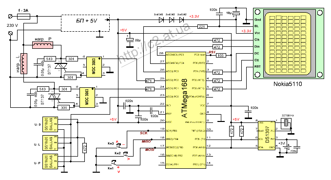
For these purposes, a device was made to control the heating of sleeping places on a microcontroller, which of course implies additional comfort.
The above scheme can, with the help of such electro-sheets (electromatrases), produce two-zone maintenance of the set temperature of sleeping places.
The control program has the following properties:
- Automatic switching on - turning off the heaters according to the real time clock, or manually according to the timer (operational setting for auto shutdown from 1 to 9 hours.).
- Setting the heating temperature for each bed.
- All data is displayed.
- Display of a graphic thermometer on the screen, for room temperature from +10 ° С to + 35 ° С
- Current hours, minutes, seconds, day of the week, day of the month, and year.
- Room temperature display (main thermometer # 1)
- Display of the temperature of warming up the sleeping place L (thermometer # 2)
- Display of the temperature of warming up the sleeping place R (thermometer No. 3).
Functions;
*The main thermometer No. 1 is a general control, giving commands for turning on the heating of sleeping places.
For example: if you set the temperature threshold on it to + 22 ° C, this will mean that when the temperature in the sleeping room is below 22, there is heating, above it is not.
**Manual one-time switching on of heaters from 1 hour to 9 hours.
***Automatically turn on - turn off the heaters according to the daily timer.
For example: you can set a warm-up schedule from 20-00 to 23-00 and in the morning from 5-00 to 6-00.
**** Thermostats No. 2,3 control the temperature of the heaters L and P.
Priorities.
Function setting *, has priority over functions **, ***, ****.
Function settings **, overrides functions ***, ****.
The setting of function *** has priority over functions ****.
Control, carried out by means of three buttons.
When operating in the main mode, Kn1 manual one-time switching on of the heaters **
Kn3 manual shutdown of heaters in mode ** or single mode ***
Kn2 enter the settings menu.
And here's what is interesting, with all the abundance of information on the indicator from exact numbers. the look first of all stops at the graphical display of the thermometer, despite the fact that the accuracy of the temperature can be determined from it approximately ± 2C °, this is nothing compared to a step of 0.1C °. But, it still attracts, and pleases the eye.)))
Fuse: MK is clocked from the internal RS oscillator, for correct operation of the program, set to the internal clock frequency 8 MHz.
Since there are a great many different programmers, and I myself use this MK for the first time, for my own "fixing the material" I will give another example of what fuses look like
read from the new ATmega168 with my programmer, and how they were installed later, it will not be difficult to make a comparison, and in the same way make the correct installation of the fuse on other programmers.
The circuit uses a switching power supply from a charging mobile phone, which very well suited this circuit,
in an unprepossessing-looking case there is an excellent power supply unit for 5 volts 0.7A!, small size, does not have a galvanic connection with the network, the output is stabilized 5 volts.
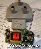
(Of course, I was lucky with power. But here 0.1A would be enough. But as they say, “they don’t look a gift horse in the mouth” :-))
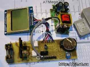
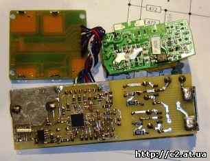
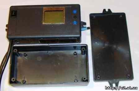
Photo of the insides before installation in the case.


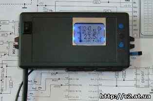

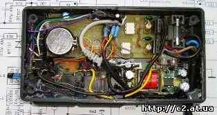

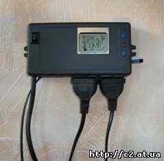


Topic of section Homemade electronics, computer programs in category General issues; Hello everyone! Not quite in the subject, but I ask for help. I bought a microlife heating pad the other day, it has 4 temperature settings.
Hello everyone! Not quite in the subject, but I ask for help. I recently bought a microlife heating pad, it has 4 temperature settings and an auto-timer for 90 minutes. Here's how to turn off the nafig timer, it's automatic and zadolbal to turn off, I need it to heat until you pull it out of the socket. I think this yellow thing is the timer. Or not?
If anyone helps him (the timer) to pull it out of the circuit, I will give him this timer!
The easiest way to make an electric heater is this one. To get started, prepare the following materials:
- 2 identical rectangular glasses with an area of about 25 cm 2 each (for example, measuring 4 * 6 cm);
- a piece of aluminum foil, the width of which is no more than the width of the glass;
- cable for connecting an electric heater (copper, two-core, with a plug);
- paraffin candle;
- epoxy adhesive;
- sharp scissors;
- pliers;
- wooden block;
- sealant;
- several ear sticks;
- clean cloth.

As you can see, materials for assembling a home-made electric heater are not at all in short supply, and most importantly, everything can be at hand. So, you can make a small electric heater with your own hands according to the following step-by-step instructions:
Using this technology, you can make an electric mini heater with your own hands. The maximum heating temperature will be about 40 o, which will be quite enough for local heating. However, for heating a room, such a homemade product will be, of course, not enough, so below we will provide more efficient options for homemade electric heaters.
Another original model of a homemade electric heater, which is suitable for local heating in a garage or room. All that is needed for the assembly is:
- a can of coffee;
- transformer 220/12 Volt;
- diode bridge;
- cooler;
- nichrome wire;
- textolite, with an area approximately the same as the diameter of a can;
- drill with a thin drill;
- soldering iron;
- cord for connecting to the network;
- push button switch.
This instruction is even simpler and you can make an electric heater from a can with your own hands in 1-2 hours. First, you need to remove the foil from the PCB and cut out the middle in it, as shown in the photo below:
After that, using a drill, you need to make holes diagonally. By the way, for this you can make a homemade mini drill according to our instructions. We fix the nichrome wire into the holes, after which we solder the wires.


We connect a transformer, a diode bridge, a cooler, a nichrome wire and a switch in one circuit.
We mount the fan in the jar using glue, and then attach the textolite as shown in the photo:
We put all the elements of a homemade electric heater in a jar, drill holes in the lid and check the device's performance!

If you want to make a more powerful device with a spiral, we recommend watching the video tutorial below:
So we move on to more powerful electric heaters that you can easily make yourself at home. To make an infrared heater, we need the following materials:
- 2 sheets of plastic, area of each 1 m 2;
- graphite powder, crushed to flour fraction;
- epoxy adhesive;
- two copper terminals;
- cord with a plug for connecting to a 220 volt network.
So, you can make a do-it-yourself room infrared heater according to the following instructions:
-
Mix graphite with epoxy adhesive in a 1 to 1 ratio.


By the way, in order for the structure to be more durable, it is recommended to place the infrared heater in a wooden frame, which can also be made by hand. Do not forget to check the resistance of the device and calculate the power before connecting!
Another model of the device, which is recommended to be assembled for heating a garage or other outbuildings in the country. All you need is an old battery, tubular heater, oil and a plug. You will also need a welding machine, welding skills and some free time. The photo below shows one of the options for a homemade oil heater.

A tubular heater is installed at the bottom left, and an oil drain / fill plug at the top. Uncomplicated design of an electric heater, which will be enough to heat a small room.
The video below clearly shows how to make an oil heater with your own hands:
Well, the last option for a home-made heater is a device that runs on 12 volts, which can be used to heat the interior of your own car. To assemble, you will need the following materials:
- old power supply from a computer;
- nichrome wire;
- residues from floor ceramic tiles;
- fasteners: bolts, corners, plates.
It is not so difficult to make an electric heater for your car yourself. The assembly process is recommended to be viewed at the master class in photo examples:


The disadvantage of such a heater is the increased risk of fire in the car, because nichrome wire is practically unprotected. In addition, you need to correctly calculate the power of the device so as not to damage the car's wiring.
That's all the ideas for assembling a homemade electric heater. As you can see, a simple electrical appliance can be easily made from various materials at hand, if you wish. If you liked the master classes, share the record with your friends so that they also know how to make a heater with their own hands for a house, garage or car!
It will be interesting to read:
Baking soda (sodium bicarbonate) readily reacts with acetic acid to form salt (sodium acetate) and weak carbon dioxide, which immediately dissociates into carbon dioxide and water. All components and reaction products are completely harmless, and the gas-rich mixture actively foams, making the pies more magnificent and forcing students to point fingers in surprise.
Sodium acetate is widely used not only as a food additive (E262), but also in the chemical industry - for dyeing fabrics, rubber vulcanization, etc. - and, of course, as part of warming "salt warmers". This substance melts at a temperature of about 58 ° C and easily dissolves in water, and if you then evaporate excess moisture from it and cool it, you can get a supersaturated solution that waits only for a slight "push" in order to instantly crystallize.
This exothermic process is accompanied by the release of a large amount of energy - from 264 to 289 kJ / kg. Unlike the production of sodium acetate, this is not a chemical reaction, but a physical process, a phase transition, and it is completely reversible. It is necessary to heat the mixture (for example, in a water bath), the acetate will again dissolve in the remaining water, and the "heating pad" can be reused.
Having briefly familiarized ourselves with the theory, let's move on to practical exercises. Of course, you can buy a “saline heating pad” at almost any pharmacy, and ready-made sodium acetate at the first suitable chemical store. But why? All the ingredients you need can be found in your own kitchen.
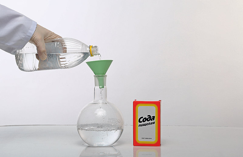
Take a suitable container (a saucepan will work fine) and add food vinegar. Keep in mind that as a result, the volume will decrease by about an order of magnitude - we had to prepare the acetate solution in several batches.
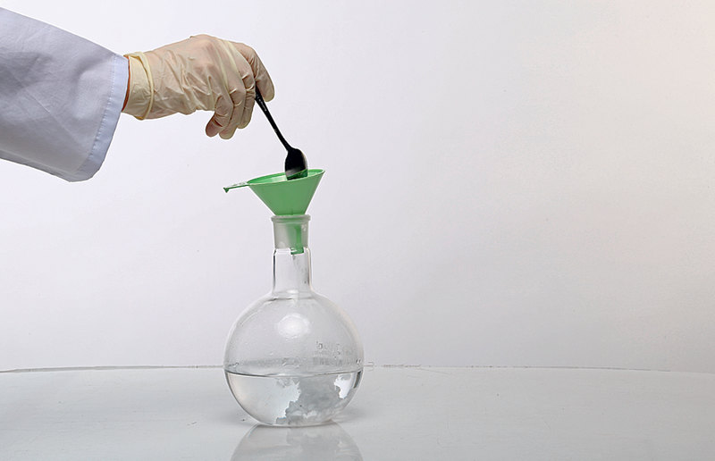
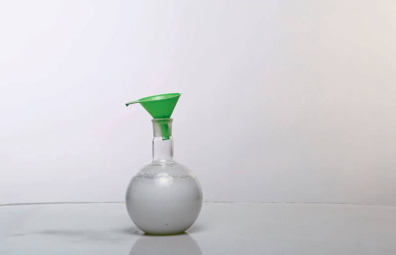
Add baking soda carefully, do not rush, letting each new portion react, otherwise you really have to get acquainted with the "chemical volcano". For every 500 ml of a 9% vinegar solution, we used 4-5 teaspoons of baking soda.
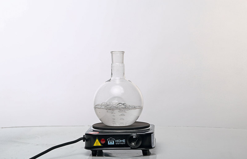
We have obtained an acetate solution, from which it remains to evaporate excess water. Place the saucepan on low heat and let the liquid simmer until fine crystals of acetate begin to appear on the sides. At the same time, the solution becomes yellowish and decreases in volume by almost 90% - this can take an hour or more.
While our solution was evaporating, we made an activator for the heating pad: we took out the base, a curved metal tape from the ruler bracelet, and cut out a circle from it, which, when pressed, bends in one direction or the other with a click. To prevent such a "button" from damaging the heating pad, it was tightened with electrical tape.
| Video (click to play). |
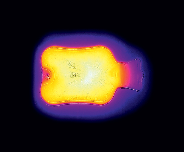
We poured the oversaturated acetate solution into a heating pad, putting our activator in it - but in principle, the reaction can be started without it. It is enough to throw in one of the crystals that remained on the walls of the dishes, and once spontaneous crystallization began with us simply from a sharp blow. The heat in such a heating pad [5] can last up to several hours, and for reuse it is enough to heat it in a water bath, again converting the acetate into a liquid form.

