On systems with automatic headlight range control, the body position sensor most often fails. Typical malfunctions: broken off points of attachment of rods, souring of rods inside silent blocks, oxidation of connector contacts, sensor internals.
VIDEO
Attention! Car service network of favorable prices. Camber check is FREE! No queues! Repair on the same day!
Download / Print topic
The electric corrector of the left headlight (357 941 295) stopped working.
You can make sure that there are no problems with the wiring by swapping the left and right correctors. Do not forget that the correction only works when the low beam is on!
If, nevertheless, the problem is in the corrector itself, then you will have to disassemble it.
The corrector consists of: a housing, an electric motor, a gearbox and a printed circuit board (it can be removed carefully by prying it with a screwdriver). Don't lose the 4 rubber support tubes, they are just underneath!
If the gears of the gearbox are intact, then the problem is either in the motor or in the board. Again, in the presence of a second serviceable corrector, it is elementary to select a non-working part by replacing the corrector boards. We change, assemble, connect. If you have not forgotten what you put where, you will be able to say for sure whether the motor or the board has died.
If suspicions fall on a microcircuit carefully painted over by the Germans, then it is “Siemens TLE4205”. I did not find it on free sale, but they can bring it to order, the issue price is 100-150 rubles. Search in Yandex or on-line warehouses through the component finder
In my case, the problem turned out to be in the electric motor. Having disassembled it, I found one of the brushes broken off.
The search for the same motor did not lead to anything, tk. it has a non-standard shaft arrangement - from the side of the terminals. However, a “MOT1 electric motor 3V, 13800 rpm, 2.1W” was found, the body of which exactly coincided with the original. The price of this device in chip & dip is already 14 rubles!
After disassembling the new motor, I was convinced of the interchangeability of the rear covers with the brush assembly.
Now is the time to remove the gear pressed onto the shaft from the old motor, warming it up with a soldering iron and / or a lighter.
A new cover with brushes can be installed on an old motor, or the rotor of an old motor can be rearranged into a new housing. Do not lose the thin washers located on the shaft!
The terminals of the new motor cover are too small, so I soldered copper pieces of the appropriate size on them. The donor was the contact plate of a conventional 220V lamp holder.
Assemble the motor, check for backlash and free rotation of the shaft. Press the gear onto the shaft, warming it up.
Having installed the motor in the corrector housing, check the free rotation of the mechanism by turning the motor gear with an awl or screwdriver. Perhaps the motor has not completely sat down in the seat, then the gears will jam.
Now you need to install the board and click on the pin of the variable resistor.
We put rubber tubes on 4 plastic pins, and a white plastic clip on a 3-pin connector. We put on the lid and run to check!
By the way, here is the instruction for the correct installation of the corrector in the headlight!
PS: Naturally, the quality of the new brushes leaves much to be desired, but they are cheap and work! Alternatives: a new Hella corrector under the order of 900r or dubious 500r from disassembly.
I am sure there are better quality donor motors, who will find - write!
VW Golf 4 / VW Bora. Replacing the front silent blocks for cars with automatic transmission.
You can also become our partner
Reason for repair:
Need to:
1. Unscrew 3 screws (flat screwdriver or TOPX 30) 2. Grasp the corner of the lower outer part of the headlight with your fingers and pull the tops towards you, this we remove the headlight from the side retainer that stands in the area of the wing 3. Now we remove the upper corner of the headlight from the wing mesh 4. We pull the headlight towards ourselves a little and by pressing the latch on the connector, slightly shaking it, remove the connector from the headlight
5. We put the headlight on the fabric "glass" down 6. Remove the rubber cap - cap and remove the three bulbs 7. We unscrew the two screws that hold the turn signal reflector (TOPX 20)
8. To remove the glass of the headlight, you need an industrial hair dryer, but due to its absence, the glass had to be removed in a different way 9. He poured hot water into a wide basin and lowered the headlight into the basin with the glass at the bottom for a while 10. Then we remove the headlamp from the water and, using a flat wide screwdriver, slightly squeeze the glass from the headlamp housing and do not forget to unfasten the side clips.
If possible, put a screwdriver on the edge and so make 2-3 circles, then lower the headlamp in hot water for a while. We remove the headlamp from hot water, squeeze the glass from the headlamp housing and cut the rubber film of the sealant with a knife ……… 15 minutes have not passed since the headlamp was detached from the glass. 11. We put the headlight without glass on the table and take the lower corners of the reflector with our hands and pull the reflector towards ourselves and slightly upward, hear a click, this means that we have docked - disconnected the reflector from the EMCF
12. The reflector did not pull off from the upper adjusting mounts 13. Raised the reflector and placed a matchbox under it 14. We take a long curly screwdriver and unscrew the two screws securing the EMCF
15. We put our fingers in the rear mounting window and, along the course of the headlight, remove the EMCF from the guides and pull the EMCF through the mounting window. 16. We boldly pull out the connector with the EMCF 17. We rewrite the code from the yellow label pasted on the EMCF 0 307 853 319 and go to look for a used EMCF and order a new one.
But, my searches during the day did not lead to anything, although I found similar photos on the network, for example: 0 307 853 301 , 0 307 853 303 , 20-5319-MA-1 , the code 0332993 etc.
By the end of the day, I decided to find out the device and, if possible, repair the EMKF
18. Remove the cover from the EMCF using a knife or a thin flat screwdriver, unfasten 4 clips 19. We take small wire cutters and on a rheostat (potentiometer or variable resistor) we cut or break off one side of the safety bar - partitions and wrap it up (while I was looking for a breakdown and punk experiments, it completely broke off).
20. The rheostat engine is connected to the worm lever. It is necessary to disconnect this connection and for this we make a hook made of wire or with tweezers we take it by the engine and pull it towards ourselves and easily pull it off the lever latch, remove it from the guides of the rheostat 21. We wring out the contacts on the engine
22. We put a cloth soaked in oil on a thin screwdriver and grease the tracks of the rheostat (do not fill in with oil, just wipe it with oil) 23. We insert the blade from a disposable machine into the guides for mounting the rheostat engine
One inconvenience in all work is the absence of an industrial hair dryer, so the melting temperature of the sealant is 90 - 300C, and this temperature is not terrible for the headlight housing.
Gender: husband
Haven't written anything for a long time. There is still no time. But then I did it once, I have to describe it.
The crux of the problem is that the right (passenger) electric headlight corrector has stopped buzzing. It was decided to quickly take Bushny from the disassembly and put it on, which I did with the help of a trip to EuroAuto (2750 rubles at the time of writing the post) and to the St. Petersburg club service (500 rubles and a pleasant conversation with the guys).
The old proofreader took it to gut.
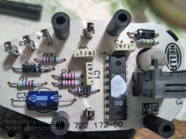
So, gut it. To remove the cover, pry off 5 ears with a fingernail or a flat screwdriver, and remove the part opposite to the metal rod with a ball. We see that the reason for the failure of the corrector is the leakage of its body. Slurry poured into the corner and the paths rotted. The board is single-layer (on the getinax CEM1 it looks like), the holes are ess-but not metallized, so it is rather delicate and does not like soldering, two-layer ones are stronger:
Now attention. To remove the board, it is necessary to unhook the copper plate from the axis, which helps the potentiometer turn, which is needed for feedback to the corrector controller microcircuit. Do this very carefully. Plastic is fragile, it can become as it was for me:
On the FTM there is a report on the autopsy of the proofreader from one of our comrades. From there I learned that the microcircuit is there - something like this: thanks to the maniacs.
What it is? This is a special microcircuit. In fact (now there will be information for those who understand electronics) - a two-threshold comparator that compares two voltages. One comes from a potentiometer in the passenger compartment. The second comes from a potentiometer, which is installed in the corrector itself. You turn the potentiometer in the cabin, the microcircuit sees a mismatch of more than a nth, and turns on the motor in the right direction. The motor drives, the headlight rises or falls, the potentiometer built into the corrector creeps until the voltage from it is equal to the voltage from the control potentiometer in the passenger compartment. Naturally, there are built-in hysteresis, motor control keys (collector 12V) and so on. In addition to the microcircuit, there are also a couple of resistors, capacitors (one for 1 nF has collapsed, I replaced it with a ceramic output), a protective diode at the power input so as not to be hit with a polarity reversal and some other nonsense, I did not even delve into it.
I did not pay the fee, tk. it was not known whether it would be fixed or not. There are good photos on the MTF.
Not really including the brain, we clean the board, connectors, change the collapsed condender, duplicate rotten roads with our feet from the resistors, clean the contacts, we get this:
Without looking for information on the internet, we figure out the topology, where there is +, where -, where is the control signal. We connect + 12V from the desktop PSU, taking into account the polarity. Between the ground and +12 we put a couple of kOhm variable, its sliding contact is in the center of the corrector connector. We spin the changer, we hear that the engine is running. Vin! For the test, you do not need to climb into Lancer.
In the last photo: ground on the left, 12 V supply on the right, control in the center.
Then we recall that we broke half of the ears that hold the lever that pulls the slider of the built-in potentiometer (copper garbage around the axis in the photo). In order to somehow support the remaining 2 ears in their difficult task, we attach a spring to the axis and close the case. At the same time, I smeared everything with plumbing smelly silicone so that it would not leak anymore (the standard rubber seal did not save). Do not forget to put rubber washers-bushings on the plastic pins (3 pcs. In the first photo). I forgot, I had to disassemble and silicone again!
Now I have a spare proofreader and satisfied curiosity, and you have my report.
Video, as it buzzes (there is also the polarity of the inclusion again):
Pay attention to the nuance of the design: upward (towards the camera) the slider of the potentiometer built inside is pushed by a healthy white gear, but downward (away from the camera) is just a copper spring, the fixing ears of which break so easily.
I hope my information will be useful to someone. By the way, the detail is German, Hella, made in Germany. Brakodels
Cars change, friends and the forum remain. [my.housecope.com/wp-content/uploads/ext/1209]
Message Maddcat »22 Mar 2012, 03:07
Message joker53 »22 Mar 2012, 19:50
Are the headlights original? If the original, then the proofreader Automotive Lighting or in other words BOSCH, see the photo of the corrector from the original headlight
Added after 7 minutes 53 seconds:
Message Maddcat »23 Mar 2012, 22:08
Message joker53 »23 Mar 2012, 22:35
Message Maddcat »23 Mar 2012, 22:56
Message Aleksandr 183 »24 Mar 2012, 13:01
Message joker53 »24 Mar 2012, 20:05
Message Maddcat »25 Mar 2012, 03:53
thanks a lot. Now you just need to make a special angle screwdriver (you can't crawl with the usual one) And, in principle, there is enough space to pull it out and put in a new one.
what has accumulated:
If you put something heavy back, then the stern of the car will sink, and the front will rise. Accordingly, the headlights will no longer shine on the road, but slightly higher. This reduces visibility and increases the risk of dazzling oncoming drivers. To correct such situations, a hydrocorrector is used.
With an increase in the mass of the car, the headlights go down a little, and the road is normally illuminated. When the load is reduced, the lights rise.
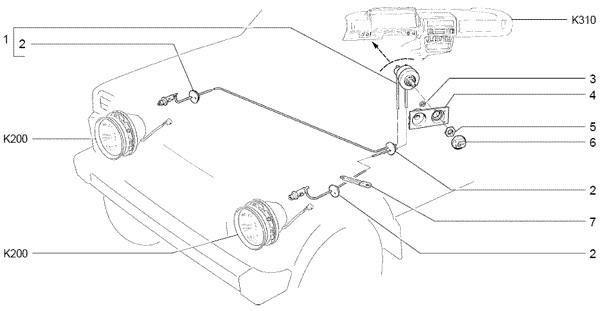
Do-it-yourself repair of a headlight hydrocorrector on a VAZ 2110 has several features. All of them are associated with the structure and location of this device. In general, this device consists of several elements:
The master cylinder, it is located behind the dashboard;
Working cylinders. They can be seen on the headlights;
Pipelines, they connect the master cylinder to the workers;
Special liquid.
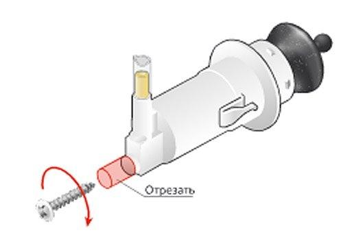
This whole structure is not demountable. In the event of a malfunction, the entire element must be replaced. The system works as follows. By turning the corrector knob, you advance the cylinder piston. Accordingly, the fluid pressure increases and the headlight cups are set in motion. They lean forward a little.
Many motorists are tormented by the replacement and installation of a hydraulic corrector. But in reality, this work is not difficult. And if everything is done correctly, then no problems should arise in this case. The replacement consists of the following steps:
First, preparation is done. Remove all clamps securing the tube to the body. It is also advisable to remove the radiator expansion tank. This will make it easier to access the headlamp. In the cabin, they remove the control knob, for this they simply pull it towards themselves;
Next, you should get the cylinder. To do this, grab the switch on the panel and pull it off. In most cases, it can be easily removed. After that, the cylinder is unscrewed from the switch. This is done using a head 22. After that, the cylinder is pulled by the tube under the torpedo. As a result, he must hang on the hoses;
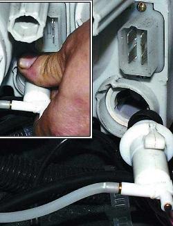
The slave cylinders are disconnected from the headlamp. They are dragged into the salon. This completes the dismantling of the corrector.
Assembly is carried out upside-down. When doing this, pay attention to the seals. They should be level. Otherwise, it will be noisy in the cabin, and in winter it will blow from there. Do not forget to check the operation of the new hydraulic corrector. If it turns out that it does not work, you will have to repeat the procedure.
The hydrocorrector should be replaced only in case of fluid leaks. Also if he cannot push the slave cylinder for some reason. Most often due to malfunctioning tubes. But sometimes the reason for the failure is not the cylinder itself. Then the repair can be made without replacing this part. The correction mechanism itself is located in the headlight block. It consists of:
Metal ball;
Plastic clip;
Bobbins;
Limiting groove on the headlamp housing;
Recoil spring.
The slave cylinder, resting on the bobbin, moves the ball along the groove, thus, the headlight lowers. When the piston of the cylinder moves back to its original position, the spring pushes the cage with the ball back. It often happens that a plastic part cracks or a spring bursts during adjustment. This is easy to fix without replacing the entire system.
To do this, you will have to remove the headlight. Remove the bulbs from it. Dismantle the glass. It is attached with a sealant and 6 metal staples. Then the spring is removed from the reflector and, after unscrewing a couple of screws, it is removed. After that, the damaged parts are replaced. Assemble in reverse order.
The hydrocorrector is not very reliable. Therefore, many motorists replace it with an electrical analogue. This is done as follows:
The battery is disconnected;
Next, the hydrocorrector is dismantled;
A new seal is installed;
Remove the corrector adjustment knob and connect a new electrical appliance to it. To do this, use the key for 22;
Connect the positive wire to the mounting block, you need to connect to socket 20, block Ш2;
The minus is attached to the nearest body stud;
A new actuator is installed in the headlamp;
The wires can be pulled over the location of the old tube;
The pads are connected to the main mechanism. The operation of the device is checked.
An electric corrector costs a little more than usual. But it is more reliable. You do not have to change this part for a new one every few months.
Conclusion ... The correct operation of the headlights is extremely important for road safety. Thus, the job of a proofreader is a must. Do-it-yourself repair of a headlight hydrocorrector on a VAZ 2110 is quite within the power of every motorist. Some of the difficulties are more than offset by travel comfort.
To characterize the dipped headlights (ECE and DOT rules regulate the adjustment of dipped beam only), the concept of a cut-off line is used. It means a conditional line where the headlight beam ends with a transition in front of the road into almost complete darkness. It is one of the main characteristics of vehicle lighting in accordance with the regulations of most countries. Here is a video of what it is, look, and everything will become clear:
VIDEO
The cut-off line should provide an optimal balance between sufficient road illumination for safe driving and a minimum level of glare for oncoming vehicle drivers. Its position is determined by the level of the body - the consequence of raising the border is a strong blinding of other drivers, and lowering it leads to a deterioration in road lighting.
A device designed to maintain a given position of the optical axis of the headlights relative to the road surface, regardless of the driving conditions (speed, modes) and vehicle load, is the headlight range control. Since 1999, its presence has become mandatory for all cars produced in Europe.
Depending on the principle of operation, the correctors can be:
with manual control (forced action);
automatic action.
As the name implies, the manual headlight range control is controlled directly by the driver. This is done using one of the various actuators:
Electromechanical headlight range control is the most high-tech, which makes it more widespread and in demand. It consists of a headlamp position switch, a gear motor and an electrical connection wiring.
The rotary switch (regulator) of the headlight position is installed in a convenient place on the instrument panel (usually to the left of the steering column). With its help, the driver sets the cut-off line that is optimal for driving (headlight level). The switch allows you to raise or lower them to one of the fixed positions.
With the help of a gear motor (photo above), consisting of a DC electric motor, a worm gear, an electronic control circuit, the rotary motion from the electric motor is converted into a translational one. Under its influence, a rod with a ball tip that fits into the latch of the lower part of the headlight (its top is hinged) makes it change the angle of inclination, which leads to a correction in the vertical plane of the cut-off line.
Video of how the manual headlight range control works:
VIDEO
A fairly reliable manual headlight range control is still inferior to the automatic one, which provides better performance and is more convenient in operation. In addition, due to the emission of high intensity light by xenon headlights, the use of automatic correction is mandatory for them. With the help of the automatic corrector, the light beam is maintained in accordance with the driving conditions (road irregularities, acceleration, turning, lifting, braking) and the load at the same level.
The automatic headlight range is also used with halogen headlights. Its design is simpler than the version with xenon headlights and allows automatic adjustment of the cut-off line depending on the position of the body.
The automatic headlight range control consists of ride height sensors (usually 2-3 sensors are used, front and rear), an electronic control unit, and actuators. The control unit monitors the ground clearance on the front and rear axles through the sensors (that is, determines the angle of inclination of the body) and, based on this data and the speed of movement, adjusts the angle of inclination of the headlights.
The operation of the sensors is based on the use of the Hall effect (a certain potential difference arises on a conductor with a direct current passing through it, injected into a magnetic field). The magnetic field in the sensors is created by permanent magnets built into the rotor, connected to the suspension by a rod. The stator is a kind of Hall sensor, the change in potentials on which determines the value of the angle of inclination of the body.
The use of only one ultrasonic sensor, which is fixed in the back of the case with the help of a hinged suspension, significantly reduces the cost of the design. This makes such correction systems available for self-installation.In this case, the manufacturer indicates the minimum permissible distance between the sensor and the road. So, for most Hella correctors it is 250 mm.
Duplication of the work of the automatic headlight range control is carried out using a traditional electromechanical headlight range control.
1. Remove the headlight and remove the old manual corrector (I had it on Logan).
2. To enlarge the hole where the old headlight range control was.
3. Attach the new device socket to the sealant (outside and inside the headlight).
4. Next, install the new Hella headlight range control into this socket.
5. The vehicle ride height sensor is mounted at the rear from below. The headlights will adjust themselves depending on the load of the car (set at 26 cm).
6. The sensor wire pulled in the tunnel where the tubes go.
That's all, the installation cost 0 rubles, and the set of the Hella universal automatic headlight range control now costs about 14,000 rubles. Powered by a 12 Volt battery.
Headlight correctors can be a standard system, or they can be installed independently. Also, the driver, if desired, can replace the corrector on his car with a more advanced one. Today, commercial enterprises offer their customers these devices from various manufacturers of various classes.
The prices for headlight correctors fluctuate, depending on their type, in a very wide range. So, a VAZ driver can purchase a hydrocorrector at a very reasonable price - from 280 rubles. up to 450 rubles An electromechanical corrector will cost 1,700 - 1,900 rubles.
As for the Hella universal auto-corrector of headlights, which can be installed on almost any car, then 13,900 - 14,200 rubles will have to be paid for it. Devices of the same class from other manufacturers differ in cost, both downward and upward.
A headlight corrector for GEELY CK can be purchased, for example, for an average of 1,000 rubles; prices for this device for Lanos fluctuate in the same range.
VIDEO
Video - installation of an electric headlight corrector for an Opel Omega A car with xenon:
VIDEO
The VAZ 2110 model cannot be called modern and advanced, and therefore a hydrocorrector is used here instead of a modern electrocorrector of head optics. Today we will talk about how to identify a breakdown and replace the hydraulic corrector, as well as whether it is possible to put an electric version instead of a standard device.
The reasons for the breakdown of the hydraulic corrector are standard:
Temperature drops that disable the hydraulic component of the unit;
The use of rubber for seals is not of the highest quality, which leads to leaks of working fluid.
VIDEO
If a leak occurs, you can no longer avoid replacing the unit.
Structurally, the headlight hydrocorrector is a set of the following components.
VIDEO
Many people blame the hydrocorrector for the refusal to adjust the headlights and rush to replace it as soon as possible. But don't jump to conclusions. There may be other causes of the malfunction.
Pay attention to the presence of hydraulic fluid leaks. If not, check the stroke.
To check the stroke of the rod, the slave cylinders are dismantled. The normal figure is in the range from 6.5 to 7.5 millimeters.
It is impossible to repair the corrector of the hydraulic type provided by the factory for the VAZ 2110, since the design of the device is not collapsible.
In the event of a malfunction, the entire assembly is subject to replacement, including the cylinders and pipes.
VIDEO
First, consider a situation in which a failed headlight hydrocorrector is replaced with a similar device. The replacement procedure is not as difficult as it seems to many. Follow the instructions and you will succeed.
VIDEO
From the name it becomes clear that the electric corrector operates on electricity, that is, it requires a connection to a storage battery.
It is not necessary to look for the reasons for such decisions from the owners of the domestic “ten” for a long time, since the electric corrector is distinguished by its reliability and high efficiency. Its breakdown occurs several times less often compared to a hydraulic corrector.
The procedure itself requires several consecutive steps.
Disconnect the negative lead from the battery.
Dismantle the hydraulic corrector cylinder from the headlight, as we described in the previous section.
Be sure to install a new O-ring during replacement.
Having gone to the salon of your car, remove the control handle of the main cylinder of the hydrocorrector. It is held by a 21 mm nut.
The positive wiring harness is connected to the 20th socket of the Ш2 block in the mounting block of your car.
The minus of the electric corrector is attached to the body pin. There are several of them and they are located under the dashboard.
The harness of the new regulator can be laid along the previously used tubes of the old hydrocorrector.
The harness pads are connected to the actuators.
Return the negative lead to the battery and check how the new device works.
VIDEO
Video (click to play).
The cost of an electric corrector today is about 1-1.5 thousand rubles. Depending on the model you choose, you will receive a certain number of adjustment positions. There are at least two of them, but the most common ones provide for 4, 12 and 15 positions.
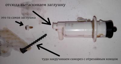 After such a repair, the concept of headlight range control is no longer applicable to the system, since the possibility of quickly adjusting the angle of inclination of the headlight reflector from the passenger compartment disappears. But such a repair has the right to life if a malfunction caught you on the road and there is simply no other way to raise the headlights.
Pull the actuators out of the headlamp assembly.

 Pull the actuators out of the headlamp assembly.


