In detail: do-it-yourself electronics repair from a real master for the site my.housecope.com.
Each person forms his own circle of contacts, and it so happened to me that in contact and in real life I am mainly surrounded by people who have this or that relation to technology. It happens that sometimes a person writes to Vkontakte and asks for help to repair a device. You answer in the standard way that you have already called on the board and you hear in response that he doesn’t know how to do it, but you really need to direct the device).
Checking radio components with a multimeter on the board
You can, of course, send a person to teach a textbook of physics, electrical engineering, google on sites devoted to electronics, saying that you are too hard to cut a branch, but decided to try to reveal some of the nuances of repairs for all these people who apparently skipped or sat through physics lessons and electrical engineers, and now suddenly decided to catch up. Remembering that electronics engineers are not born, but become.
Measuring DC current with a tester
So, we have a multimeter and with it you can measure various quantities, for example, such as current, alternating and direct, which we do not need for repairs as often as other quantities. Although there are test points on the diagrams at which you need to break the circuit and measure current currents or voltages. In such cases, it is indicated directly on the diagram what voltage or current should be present at this point.
Test point measuring current on the diagram
We measure the voltage on the board much more often than currents, because if there is no voltage in the circuit, for example, on the power connector, then this is a clear sign that the circuit is not functioning correctly. These measurements are referred to as hot or no-power measurements and must be performed with normal electrical safety precautions. Since on boards, for example, switching power supplies, in some parts of the circuit, we have high voltage. Other measurements, in particular resistance measurements or sound continuity measurements, are carried out only in a de-energized device!
| Video (click to play). |
This is an important rule, it is enough to make a mistake once and measure the resistance instead of voltage, or the same on the audio continuity, and at best you will have to look for a circuit for a multimeter and change resistors, which most often come in a planar case and have small dimensions, for example 0805 or even 0603. In the worst case, you will burn the ADC of the device - that very black drop, and the device will not be subject to repair, or its repair will be at least unprofitable.
Multimeter ADC IC
When we measure the voltage on the board in an unfamiliar place without knowing exactly what value we should have, always set a higher value on the multimeter. For example, if the power supply gives out 35 volts and measure at the output, choose 200 volts, if 5 volts, then 20 volts. The same is with the resistance: if the resistor is marked not with colored rings, but for example of the MLT type and it is impossible to decipher the marking, select the 2 MegaOhm mode on the multimeter, followed by a decrease in the measurement limit to ensure the required accuracy.
Always when repairing switching power supplies that have in their circuit, for example, electrolytic capacitors for a voltage of 400 - 450 volts and a nominal value of 100 - 150 microfarads, discharge the capacitor by shorting the terminals together with a screwdriver with an insulated handle. The same applies to the repair of ATX power supplies - there the voltage of electrolytic capacitors is less, only 200 volts, but it must be admitted that the tingling is not weak anyway.
CRT board
Sometimes, for example, on the boards of CRT TVs, there are several such capacitors with a high operating voltage, and not just one filter capacitor. They are usually somewhat smaller than the filter capacitor. What is the basis for checking radio components, using an ohmmeter, and sound dialing? Let's recall Ohm's law: the lower the resistance at a constant voltage, the greater the current.
If suddenly the resistance of one part suddenly becomes very small, then according to Ohm's law in the section of that circuit, currents will flow that greatly exceed the permissible ones, for example, resistors may not like it a lot - they will overheat, turn black, and in especially severe cases even burn out ... This fully applies to any semiconductor.
Maximum graphics card temperature
We all know, for example, by the thermal profile of video cards, that the temperature of the order of 75 - 85 degrees is usually the limit for silicon, during prolonged operation, and the video card eventually gives out artifacts, and for example, the chipset on the motherboard begins to heat up abnormally, and as a result, in In the best case, the computer will not work stably, and in the worst case, it will not turn on at all. So, transistors and diodes, like any microcircuits, are all the same semiconductors, which will simply burn out when excess currents and an increase in temperature appear.
Burnt resistor is normal
How can you determine that a part has burned out using a multimeter? Resistors very often go into an open circuit during combustion, if the resistor does not ring even at the limit of two Megaohms - most likely it burned out. What does a resistor burn out from a physical point of view? This means that he has a very large resistance between the terminals, and if so, then, according to Ohm's law, microscopic currents conditionally flow there. Which can be considered an open circuit. Any semiconductors, on the contrary, very often go into a short circuit or low resistance, but this is not always the case. Why this parameter, the resistance of the radio component is so important for the operation of the circuit, we have disassembled.
Planar resistor
Now we can in general, in principle, evaluate any object from the point of view of its conductivity for an electric current. Let us examine, for example, such a situation - why a TV brought from the garage from the cold cannot be immediately connected to the network, but you need to let it stand for 30-40 minutes in the warmth, and let the temperatures even out.
The fact is that droplets of water can form on the terminals of radio components, from frost, and water is a good conductor and resistance between closely spaced terminals of a microcircuit containing, for example, a power transistor that turns on the device, it turns out to be closed, two or even all three terminals , transistor or microcircuit, among themselves. What does this lead to?
The designation of the terminals of the transistor
Those pins of the microcircuit or, for example, the base terminal of the transistor, they are connected to the low-voltage part of this device, and the supply of high voltage to them will lead to their obligatory breakdown, a decrease in resistance, or even a short circuit, and at the same time they can take with them any other parts on scheme. For what purpose is it necessary to regularly clean the dust from the circuit boards of the device? The first is dust, this is a heat insulator, it interferes with the removal of heat from radio components, which heat up during operation, their temperature rises and they fail.
The second reason is dust on the board between the terminals, this is certainly not a conductor, but it cannot be said that it is a very good insulator. Under normal conditions, it may not break through dust, but after bringing in equipment from frost - everything can be, because dust saturated with moisture has a lower resistance than dry dust, and it dries, most likely, longer than just a little frost on the board.
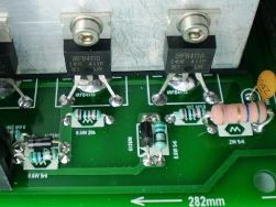
Switching power supply board
Knowing how to analyze a circuit and a printed circuit board, you will know what is the approximate resistance, in total, of all parallel-connected parts, should be at one point or another. Even when we ring non-semiconductors with a multimeter on a sound continuity, we measure the same resistance between certain parts of the circuit.
Sound Continuity of the Multimeter
If we hear a sound signal, then the resistance between the points at which we are measuring is lower than 50 Ohm, the numbers are of course approximate, but I think the principle is clear. Knowing what resistance this or that part has in the working and in the non-working state, we can analyze the device for operability without having a schematic diagram. With the scheme, of course, everything is much simpler, but there is a technique, for example, little-known Chinese brands, for which you will not find schemes anywhere. In this case, only the analysis of the operation of the circuit, the principle of its operation, experience in working with similar circuits, or the search for an analogue of our circuit, albeit with other reference designations on the diagram, will help us.
Positional designation on the diagram and rating
In this case, you will need to track each node along the paths, but this is certainly better than the absence of any documentation at all.
The purpose of writing this article is to show novice electrical engineers that knowledge of the basics of repairing equipment is not only interesting, but also in our financially difficult time, can help radio amateurs and electronics engineers, save some of the money on self-repair. And in the future, as you level up, you will regularly earn extra money in this area. This is now becoming especially important, since people now more and more often turn to for repairs, and not just throw away the old and buy new household appliances, as before. Successful repairs to everyone! AKV.
In the life of every home craftsman who knows how to hold a soldering iron in his hands and use a multimeter, there comes a moment when some complex electronic equipment breaks down and he has to make a choice: take it to a service for repair or try to repair it on his own. In this article, we will break down the techniques that can help him with this.
So, you have broken any equipment, for example LCD TV, where do you need to start repairs? All craftsmen know that it is necessary to start repairs not with measurements, or even immediately re-soldering the part that aroused suspicion of something, but with an external examination. This includes not only inspecting the appearance of the TV boards, removing its cover, for burnt radio components, listening in order to hear a high-frequency squeak or clicking.
To begin with, you just need to turn on the TV to the network and see: how it behaves after turning it on, does it respond to the power button, or the standby LED blinks, or the image appears for a few seconds and disappears, or there is an image, but there is no sound, or vice versa. By all these signs, you can get information from which you can push off with further repairs. For example, in the blinking of the LED, at a certain frequency, you can set a breakdown code, self-test of the TV.
TV error codes by flashing LED
After the signs are installed, you should look for a schematic diagram of the device, or better if a Service manual for the device is released, documentation with a diagram and a list of parts, on special sites dedicated to electronics repair. It is also not superfluous, it will be in the future, to drive into the search engine the full name of the model, with a brief description of the breakdown, conveying in a few words its meaning.
True, sometimes it is better to look for a diagram by the device chassis, or by the name of the board, for example, a TV power supply. But what if the circuit still could not be found, and you are not familiar with the circuitry of this device?
In this case, you can try to ask for help on specialized forums for the repair of equipment, after carrying out preliminary diagnostics on your own, in order to collect information from which the masters who help you can push off. What stages does this preliminary diagnosis include? To begin with, you must make sure that power is being supplied to the board, if the device shows no signs of life at all. It may seem trivial, but it will not be superfluous to ring the power cord for integrity, in the audio dial mode. Read here how to use a regular multimeter.
Tester in the mode of sound dialing
Then the fuse is ringing, in the same multimeter mode. If everything is fine with us here, you should measure the voltages at the power connectors going to the TV control board. Typically, the supply voltages present on the connector pins are labeled next to the connector on the board.
TV control board power connector
So, we measured and we do not have any voltage on the connector - this indicates that the circuit is not functioning correctly, and we need to look for the reason for this. The most common cause of breakdowns found in LCD TV is banal electrolytic capacitors, with an overestimated ESR, equivalent series resistance. Read more about ESR here.
Capacitor ESR Table
At the beginning of the article, I wrote about the squeak that you may hear, and so, its manifestation, in particular, is a consequence of the overstated ESR of small capacitors standing in the standby voltage circuits. To identify such capacitors, a special device is required, an ESR meter, or a transistor tester, although in the latter case, the capacitors will have to be soldered for measurement. A photo of my ESR meter that allows you to measure this parameter without soldering is posted below.
What if such devices are not available, and suspicion fell on these capacitors? Then you will need to consult on the repair forums, and clarify in which node, which part of the board, the capacitors should be replaced with obviously working ones, and only new (!) Capacitors from the radio store can be considered as such, because used ones have this parameter, ESR may also be off scale or already on the verge.
Photo - swollen capacitor
The fact that you could remove them from a device that previously worked does not matter in this case, since this parameter is only important for working in high-frequency circuits, respectively, earlier, in low-frequency circuits, in another device, this capacitor could function perfectly, but have an ESR parameter that is highly off-scale. The work is greatly facilitated by the fact that capacitors of a large denomination have a notch in their upper part, along which, if they become unusable, they simply open, or a swelling forms, a characteristic sign of their unsuitability for any, even a novice master.
Multimeter in Ohmmeter Mode
If you see blackened resistors, you will need to ring them with a multimeter in ohmmeter mode. First, you should select the 2 MΩ mode, if the screen shows values that differ from one, or the measurement limit is exceeded, we should accordingly reduce the measurement limit on the multimeter to establish its more accurate value. If there is a unity on the screen, then most likely such a resistor is in an open circuit, and it should be replaced.
Resistor color coding
If it is possible to read its denomination, according to the marking with colored rings applied to its case, it is good, otherwise, one cannot do without a diagram. If the circuit is available, then you need to look at its designation, and set its rating and power. If the resistor is precision, its (exact) value can be dialed by connecting two ordinary resistors in series, larger and smaller, the first we set the value roughly, the last we adjust the accuracy, and their total resistance will add up.
Transistors are different in the photo
Transistors, diodes and microcircuits: it is not always possible to determine the malfunction by their appearance. A measurement with a multimeter is required in the audible dial mode.If the resistance of any of the legs, relative to some other leg, of one device is zero, or close to it, in the range from zero to 20-30 ohms, most likely such a part must be replaced. If this is a bipolar transistor, you need to call in accordance with the pinout, its p-n junctions.
Checking the transistor with a multimeter
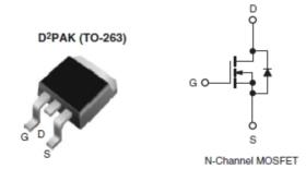
Most often, such a check is enough to consider the transistor as working. A better method is described here. In diodes, we also cause a p-n junction, in the forward direction, there should be numbers of the order of 500-700 when measured, in the opposite direction, one. The exception is Schottky diodes, they have a lower voltage drop, and when dialing in the forward direction, the screen will display numbers in the range 150-200, in the opposite direction there is also one. Mosfets, field-effect transistors, it is not possible to check with an ordinary multimeter without soldering, it is often necessary to consider them conditionally working if their outputs do not ring among themselves shortly, or in low resistance.
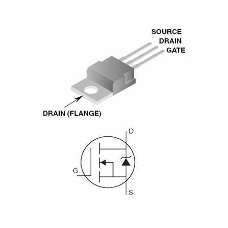
Mosfet in SMD and regular case
In this case, it should be borne in mind that the mosfets between the Stock and the Source have a built-in diode, and when dialing, there will be readings of 600-1600. But there is one nuance here: if, for example, you ring the mosfets on the motherboard and hear a sound signal at the first touch, do not rush to record the mosfet in the broken one. In its circuits, there are electrolytic filter capacitors, which, at the moment of the start of charging, as you know, for some time behave as if the circuit is short-circuited.
Mosfets on the PC motherboard
This is what our multimeter shows, in the mode of sound dialing, squeaking, for the first 2-3 seconds, and then increasing numbers will run on the screen, and the unit will be set as the capacitors charge. By the way, for the same reason, in order to save diodes of the diode bridge, a thermistor is installed in the switching power supplies, limiting the charging currents of electrolytic capacitors, at the moment of switching on, through the diode bridge.
Many acquaintances of novice repairmen who apply for remote consultation in, are shocked - you tell them to ring the diode, they will ring and immediately say: it is punctured. Here, as a standard, the explanation always begins that you need to either raise, remove one leg of the diode, and repeat the measurement, or analyze the circuit and the board, for the presence of parallel-connected parts, in low resistance. These are often the secondary windings of a pulse transformer, which are just connected in parallel with the terminals of the diode assembly, or in other words, a double diode.
Parallel and series connection of resistors
Here it is best to remember once, the rule of such connections:
- When two or more parts are connected in series, their total resistance will be greater than the greater each, separately.
- And with a parallel connection, the resistance will be less than that of each part. Accordingly, our transformer winding, which has a resistance of 20-30 Ohm at best, by shunting, imitates a “punctured” diode assembly for us.
Of course, unfortunately, it is not realistic to reveal all the nuances of repairs in one article. For preliminary diagnostics of most breakdowns, as it turned out, a conventional multimeter used in the modes of a voltmeter, ohmmeter, and sound continuity is sufficient. Often, if you have experience, in the event of a simple breakdown, and the subsequent replacement of parts, this is where the repair is completed, even without the presence of a circuit, carried out by the so-called “scientific poke method”. Which of course is not entirely correct, but as practice shows, it works, and, fortunately, not at all as shown in the picture above). Successful repairs to everyone, especially for the site of the Radiocircuit - AKV.
A soldering iron should always be at hand with an electrician. A few simple instructions for building a DIY tool are provided here!
About what a homemade battery charger consists of and how to assemble all the elements into one circuit, we are talking in this article!
Diagrams for assembling a surge protector at home. Find out how you can make a surge protector from available tools.
Diagrams for assembling a twilight switch from improvised means. Find out how to make a photo relay with your own hands!
Simple Cotton Switch Assembly Ideas. Diagrams and video instructions that will help you make an acoustic switch with your own hands.
How to make a pass-through light switch from a key model, intermediate relay or pushbutton switches.
Step-by-step instructions for assembling a homemade soldering station from available tools.
Instructions for assembling a motion sensor from available tools. Circuits for making a simple detector for turning on lighting at home.
Diagrams for assembling a simple thermostat at home. Find out how to make a temperature controller for a refrigerator, underfloor heating, and even an incubator!
Instructions for assembling time relays based on the NE 555 timer and on transistors. Learn how to make a simple DIY time relay.
Learn how to make a simple DIY dimmer. In the article, we have provided assembly diagrams with a detailed description of the manufacture of a dimmer.
If you don't have a boiler at hand, but you need to heat the water, you can assemble a homemade product from available tools. We have provided assembly instructions in this article!
Automatic gates make life easier for motorists living in private houses, because you can enter the courtyard without leaving the car. On how to make a do-it-yourself gate opening mechanism, [. ]
The procedure for assembling a homemade transformer. Find out how to calculate the parameters of the device and how to wind the wire on the spool.
Arduino coded lock diagram. The principle of operation of an unusual lock, as well as the code with which it will work.
Not sure how to assemble a simple wind generator from available tools? For you, we have provided some simple ideas for homemade wind turbines.
Find out how to make the simplest projector for your phone and laptop out of handy tools! For you, we have provided step-by-step instructions with photos and videos!
Making an electric heater for your home or car is quite simple! We have provided assembly instructions in the article!
The best homemade garland assembling workshops!
The control light is one of the essential tools of an electrician. How to make it yourself, read here!
Making a simple welding machine at home is not at all difficult. You can be convinced of this by looking at 2 detailed instructions!
An instruction with photo and video examples that will teach you how to independently make a perpetual motion machine from scrap materials.
With this homemade product, you can charge your phone without electricity or light a light bulb. Simple master classes on assembling a generator based on the Peltier module.
The laser level will allow you to smoothly draw the strobe when wiring. Read about how to make a simple level from scrap materials here!
A soldering iron should always be at hand with an electrician. A few simple instructions for building a DIY tool are provided here!
Want to do something simple and useful? We recommend that you look at the photo instructions for assembling a mini drill at home!
Since you have decided to become a self-taught electrician, then surely after a short period of time you will want to make some useful electrical appliance for your home, car or summer cottage with your own hands. At the same time, homemade products can be useful not only in everyday life, but also made for sale, for example, a homemade battery charger. In fact, the process of assembling simple devices at home is not difficult. You just need to be able to read the diagrams and use the tool for radio amateurs.
As for the first point, before you start making electronic homemade products with your own hands, you need to learn how to read electrical circuits. In this case, our brief overview of all the symbols on electrical circuits will be a good helper.
From tools for novice electricians, a soldering iron, a set of screwdrivers, pliers and a multimeter will come in handy. Some popular electrical appliances may even require a welding machine to assemble, but this is a rare case. By the way, in this section of the site, we even told how to make a simple do-it-yourself soldering iron and the same welding machine.
Special attention should be paid to the materials at hand, from which every newbie electrician can make elementary electronic homemade products with his own hands. Most often, old domestic parts are used in the manufacture of simple and useful electrical appliances: transformers, amplifiers, wires, etc. In most cases, it is enough for novice radio amateurs and electricians to look for all the necessary tools in the garage or shed in the country.
When everything is ready - the tools are assembled, the spare parts are found and the minimum knowledge is obtained, you can proceed to the assembly of amateur electronic homemade products at home. This is where our small guide will help you. Each provided instruction includes not only a detailed description of each of the stages of creating electrical appliances, but is also accompanied by photo examples, diagrams, as well as video lessons that clearly show the entire manufacturing process. If you do not understand at some point, then you can clarify it under the entry in the comments. Our experts will try to advise you in a timely manner!
Finally, I would like to note - if you know how to create some interesting electrical appliance with your own hands, and want to share your experience, you can send your own instructions to us by mail via the Feedback form. In turn, we promise to keep the authorship for you so that other visitors know whose electronic homemade product it is!
Technological progress is transforming our streets and houses, changing the style of communication, regulating the style of behavior, and filling the world around with a huge amount of various electronics. The widespread popularization of the Internet made it impossible to have at least one computer in every family. Over time, electronic circuits and entire devices fail and become ordinary junk that cannot be repaired or restored. But even in this case, you can benefit from the failed equipment, enriching the interior with another craft. Our section "DIY electronics"Is dedicated to the manufacture of homemade products from non-working household appliances, as well as the creation of all kinds of electrical devices using improvised means.
We will tell you about the production of a mini-battery at home, and also demonstrate how you can make a table by installing an LCD screen from a TV or monitor into it, or replace a cassette audio system in a car with a built-in computer. On the pages of our section, you will learn how to make an LED stand and decorations for the New Year's Eve with LED elements inside.
Most of the homemade products from this section will appeal to the representatives of the strong half of humanity. Those who like to delve into technology will find an outlet for themselves on the pages of Samodelkin. If you understand electronics at a sufficient level, the creation of the masterpieces presented on the site will not be difficult and will help you to usefully spend one of the long winter evenings. The most important thing is to have patience and the necessary components. The process of creating electronic and electrical appliances requires maintaining safety measures and careful handling of electricity.Therefore, we strongly recommend not only to be present, but also to actively participate in the creation of any crafts from this section that interested your children.
If you have your own experience in the field of creating various electrical crafts, we will be happy to share your detailed reviews with our many visitors. Send your options for homemade products using electronics, detailed photos and video instructions, and we will immediately publish your ideas in the vastness of our portal.
Or enter the site if you are already registered.
Generally speaking, we can say that the field-effect transistor fails either from overvoltage or from overheating. And if the reasons for exceeding the permissible parameters are not allowed, then the transistor will retain both its operability and the operability of neighboring components, not to mention the nerve cells of the owner of the device for which this transistor was intended.
Of course, lithium batteries left in the sun is a well-known story: your e-book or tablet will swell if left on a beach towel. And all because at elevated temperatures, the normal operation of the lithium battery is disrupted, excessive gas evolution begins in it. Therefore, it is best to leave these devices at least in the shade, and preferably at home.
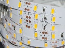
Before proceeding, I note that the main emphasis will be placed on common tapes with 12V power supply, 24V tapes are similar in design, and at the end, the features of repairing network (220V) tapes will be considered. First, let's figure out what the LED strip consists of and why it is flexible. A led strip can be split into two parts: FPC and LEDs and current limiting resistors. On one side, the flexible PCB is coated with an adhesive. The second side has a metallized layer.
If there is no voltage, we disassemble the outlet and see if the wires are intact.If not, you need to look for problems in the wiring, but for now, an extension cord from the nearest working outlet will help you. If there is voltage in the outlet, then you need to check the cord of the washing machine, for this you need to inspect the machine from the outside and determine where the wire goes, then you need to disassemble the machine case, and first you can try to remove the top cover.
Heating elements sooner or later burn out, while they can both simply stop working and punch onto the case, which will cause a danger of electric shock. Let's look at the reasons for their failure, structure, differences and replacement methods. The electric heater consists of a tubular body, inside which there is a spiral or a thread made of a material with high resistivity, such as nichrome, fechrome, etc. The coil is separated from the body by an electrically insulating but thermally conductive material such as periclase.
His main profile is the repair of DVD, CD players, which made Andrey Golubev popular in his time. Then he began repairing microwave ovens, LCD TVs, monitors and other consumer electronics. And so the hobby turned into a real business, and then a desire arose to share the accumulated experience with others. Have you ever watched how experienced specialists easily find faults and masterfully handle tools and measuring instruments? Many people are ready to constantly admire someone's work, without even thinking that they can learn all this.
Why doesn't the microwave heat the food? Consider the possible causes of a malfunction of mechanically controlled microwave ovens. We will also give an illustrative example of troubleshooting a microwave oven. If the microwave oven works, but does not heat food, then first of all you need to make sure that the voltage in the network is not too low. It is often mistakenly concluded that the microwave is malfunctioning.
How to organize light and music at home, at the dacha, or a new use of the gadget.
Many users of the popular MT8057 carbon dioxide (CO2) detector ask questions about how to implement supply or exhaust ventilation control with this detector. We want to offer a solution to this problem.
Installing a phone battery into a common flashlight instead of R20 batteries.
This advice will be very useful for motorists and others who get in the way of long USB cords, but there is no desire to cut it.
I saw similar flashlights on the sites of Chinese goods, I decided to make the same.
We make homemade bullet-shaped headphones.
Hello everyone. I want to share with you a simple circuit, namely a voltage regulator for 220 volts alternating current.The design is quite simple and does not require a large investment, and any novice radio amateur can assemble such a circuit.
Sometimes it happens that the necessary charger for the phone is not at hand, for this purpose it was decided to make a universal charger "Frog".
By knowing the basic principles of induction, many interesting products can be made.
I formulated the task for myself simply: to control the lighting in the house not only from the switch, but also via the radio channel. The problem is solvable, but the difficulty is to run it all on standard wiring and maintain the convenience of control from a standard switch.
It is quite easy to make such columns yourself, and the cash costs will be very small. They will also have an unusual and interesting design.
You won't surprise anyone with trendy headphones today, but what if they look like bullets? You can make this cute accessory with your own hands. Old headphones are the subject of modernization.
The boombox is an indispensable accessory for home parties and celebrations. Making it with your own hands is not so difficult, it is not at all costly - both financially and physically. Making it yourself is not so difficult. All work on the player will take 2-3 hours.
Remote control for TV and DVD in the form of a toy pistol. Very convenient, I have been using it myself for more than 5 years.
Clip-on headphones can be easily converted into a familiar headphone. The shackle for them can be made in a matter of minutes.
Automatic curtain without microcircuits and radio parts.
Portable charger for your phone or tablet from the battery.
Making a portable charger for a tablet and a phone from a regular battery from a screwdriver.
The thin wires of the headphones get tangled and damaged every now and then. A protective case for your headphones will eliminate these problems.
| Video (click to play). |
An easy and quick way to shorten long wires on chargers, usb cables, etc.

