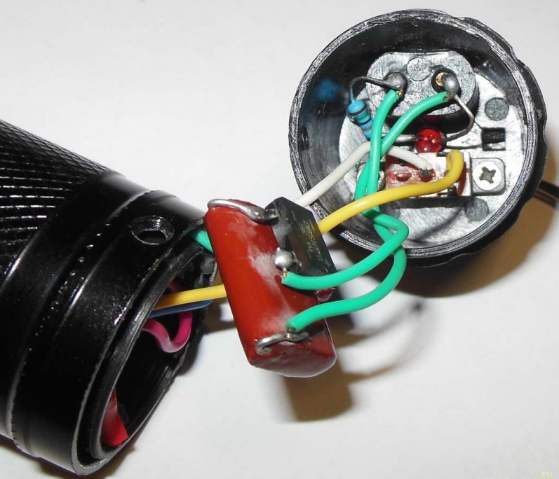
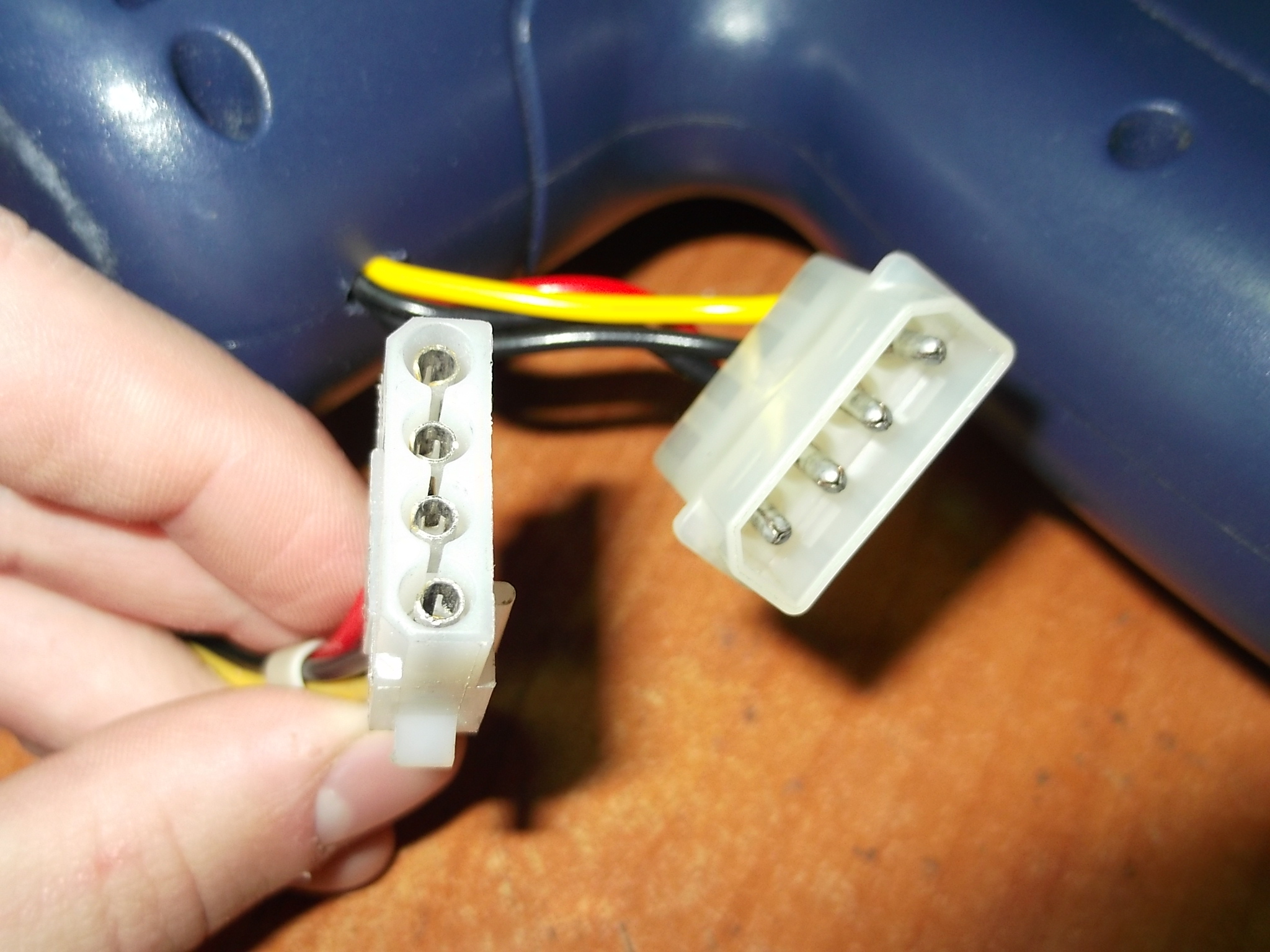
In detail: DIY repair of stun guns from a real master for the site my.housecope.com.
One of the most common shocker malfunctions is a missing spark or a constant electric arc instead of a variable arc. Also, the capacitor in the device may break, the microcircuit breaks down, and the battery oxidizes. There are many reasons why a stun gun breaks down. This is the ingress of moisture, wear of parts and assemblies, improper charging of the device and non-observance of the operating instructions.
Why is it not recommended to repair the stun gun with your own hands? It's simple: in order to eliminate a malfunction, it is necessary to identify its cause, and an amateur cannot do this. The only thing that an ordinary user can do is install a battery in the device instead of a battery that has failed. All other faults should be eliminated exclusively by professionals.
Also, repairs are carried out by specialized service centers, where masters work who are well versed in the features of such devices and can diagnose them.
There is one caveat: almost all ESDs work according to an individual electrical circuit, and it is difficult to find its description or image. Accordingly, the craftsmen reproduce the circuit only after visual analysis: they disassemble the device and study its internal structure. That is why, often after repairs, ESHU does not work as before. That is, in many cases it is more expedient to purchase a new device than to repair the old one.
An electroshock device (stun gun), abbreviated as ESHU, is a publicly available special means of protection against offenders and an effective means of deterring and protecting animals, such as dogs, when attacked.
| Video (click to play). |
Shockers on the market are presented in a wide range, but the principle of operation of all models is the same. They differ from each other only in the voltage on the electrodes, arc power, reliability and the availability of additional services, such as a flashlight and built-in charger, and others.
The main consumer parameters of any shocker are the open circuit voltage on the spark gap electrodes and the arc power. According to GOST R 50940-96 “Electroshock devices. General specifications. " Shockers by voltage on the electrodes are divided into five groups. The first is from 70 to 90 kV, the second is from 45 to 70 kV, the third is from 20 to 45 kV, the fourth is from 12 to 20 kV and the fifth is up to 12 kV inclusive. And according to the power of the arc impact - into three types. The first is from 2 to 3 watts, the second is from 1 to 2 watts and the third is from 0.3 to 1 watts.
Depending on the combination of the type and group possessed by a particular model of the stun gun, according to GOST R 50940-96, it can be attributed to one of five classes. To which class the stun gun corresponds, it is easy to find out from the table below. For example, a stun gun of the second type of the third group belongs to the third class.
First class stun guns are very powerful and expensive, they are weapons for special forces. For personal protection, a second or third class shocker is quite suitable.Shockers of the fourth and fifth classes are more suitable for intimidating the attacker than for real protection.
Attention, if you decide to buy a stun gun, then consider the following. For a temporary paralysis of the physical strength of an attacker, the time of continuous impact of a shock discharge on his body should be about 3 seconds. With a shorter exposure time, you will only anger the offender and then it is quite possible that you yourself will fall under the influence of your own shocker. It is permissible to use a shocker only if you are sure that you can keep the shocker pressed by the electrodes to the enemy's body for three seconds.
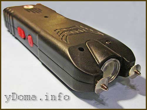
I had to repair a JSJ-704 type stun gun with a flashlight. The appearance of this shocker is shown in the photo above. By external signs, the shocker was serviceable, the LED indicating the battery charge was on when the shocker was connected to the network. The flashlight worked, the ready-to-discharge LED was also on, but when the discharge button was pressed, nothing happened. It became obvious that the fault lies in the high-voltage converter circuit.
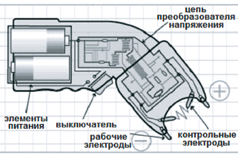
All stun guns, regardless of model and manufacturer, work on the same principle. Voltage from a battery or batteries is fed to a high frequency generator, which converts DC voltage into AC voltage. An alternating voltage is applied to a step-up high-voltage transformer, the secondary winding of which is connected directly or through a voltage multiplier to the external electrodes of the shocker. When the stun gun is turned on, a powerful electric arc arises between the electrodes.
The photo shows the electrical schematic diagram of the JSJ-704 stun gun.
The circuit consists of several functional units. The GB1 battery charger is assembled on the capacitor C1 and the diode bridge VD1. C1 limits the charge current to 80 mA, the diode bridge rectifies the voltage. Resistor R1 serves to discharge the capacitor C1 through it after disconnecting the shocker from the mains voltage to prevent the discharge of the capacitor through the human body when accidentally touching the terminals of the plug.
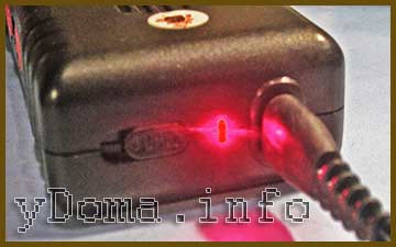
The HL1 LED serves to indicate the connection of the shocker to the 220 V electrical network, R2 serves to limit the current flowing through the HL1. This part of the circuit does not directly participate in the work of the shocker and serves only to charge the battery and may be absent in models of other shockers. Charging time for a fully discharged battery is 15 hours.
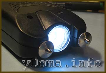
LED HL2 with current limiting resistor R3 is a flashlight. The flashlight turns on when the S1 switch slider is moved to the middle position. The flashlight is placed between the shock arrestor and is convenient in the dark. In some models, shockers may be absent.
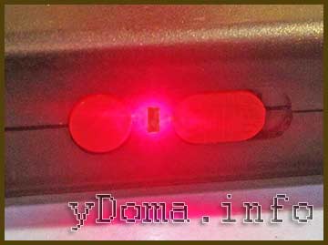
The HL3 LED with a current-limiting resistor R4 are used to indicate the inclusion of the shocker in the ready-to-use mode. To prevent accidental switching on to the discharge mode, triple protection is provided in the form of three switches. In order for a discharge to appear between the electrodes, you must first move the slide switch S1 (located next to the round button) to the extreme right position, then the second slide switch S2 (located next to the socket for connecting the shocker to the mains for charging) to the right position, then the HL3 LED will light up, informing that the shocker is ready to discharge. And only after that, when you press the round pusher of the return button S3 "Start" itself, a discharge in the form of a blue arc will appear between the electrodes.
Due to the fact that the halves of the shocker body were fastened together with four self-tapping screws, it was not difficult to disassemble it.
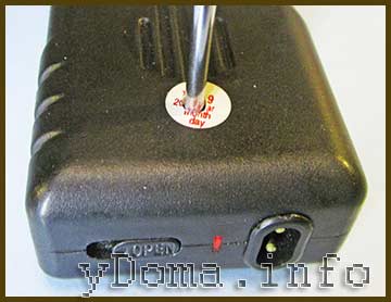
The heads of three self-tapping screws were clearly visible in the countersunk holes, and the fourth was sealed with a label. After unscrewing all the screws, the halves are easily detached.
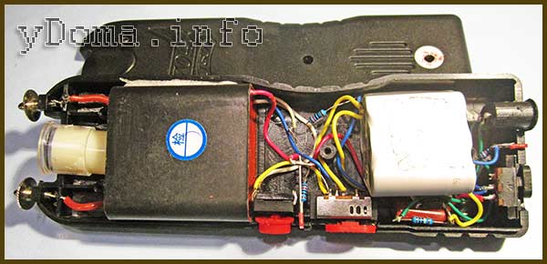
After removing the cover, the following picture was revealed.As you can see in the photo, the installation of the stun gun parts is carried out in a hinged way, there is no printed circuit board. The high-voltage converter is filled with a compound. This is good, as it is protected from moisture and therefore more reliable, but it is bad that the converter is not repairable. It should be noted that although the shocker is also made in China, all the soldering is performed with high quality and reliability.
Attention, when repairing a stun gun, extreme care must be taken so as not to accidentally touch the discharge electrodes while the stun gun is operating. Killing will not kill, but unpleasant sensations are guaranteed.
The repair of any electronic device begins with checking the power supply. Therefore, the first step is to check the performance of the battery or batteries. The check can be done with a multimeter. If the shocker runs on batteries, then in addition to their serviceability, you need to check the condition of the contacts in the battery compartment. It happens that they oxidize or weaken their spring properties.
When the "Start" button was pressed with the "Readiness" indicator lit, the discharge did not occur, but the voltage at the battery terminals, equal to 7.2 V, did not drop. Therefore, it is not about the battery. I checked the voltage by pressing the "Start" button on the input terminals of the High Voltage Converter, it dropped to several volts. This voltage was enough for the HL3 LED to glow, but not enough for the converter to work.
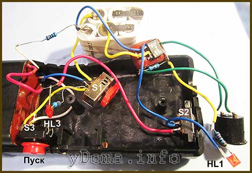
Therefore, the fault was in poor contact of one of the switches, S1, S2 or S3. I short-circuited the S2 conclusions with a jumper and the stun gun started working. To restore the shocker's performance, you need to clean or replace the faulty switch.
If the stun gun has not been turned on for a long time, then in some types of switches the contacts are oxidized and often to restore their performance, it is enough to turn it on and off twenty times. Then the oxide will be erased, and the switch will work again.
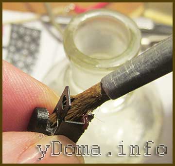
But since the shocker was opened and there was access to the contacts in the faulty switch, the wires were soldered from the switch and the contacts were cleaned with a brush moistened with alcohol. During the time when the contacts were wet with alcohol, the switch was switched intensively. After soldering back to the wire terminals, the shocker's work was restored. As you can see, we managed to repair the stun gun with our own hands, spending very little time.
Here is a video demonstrating the operation of the stun gun after repair. As you can see, a rather powerful arc arises between the electrodes, accompanied by a strong sound of a wide spectrum. Animals, especially dogs, do not like this sound very much; they run away with their tails between their legs.
Stun gun - the device is very useful, but what is sold in the store will not protect you in real "combat" situations. It is worth reminding once again that according to GOST, civilians (mere mortals) cannot wear and use electroshock devices, the power of which exceeds 3 watts. This is ridiculous power, which is only enough to scare away dogs and drunken drunks, but not for defense.
An electroshock device must be highly effective in order to protect its owner in all situations, but in the store, alas ... no.
So what is to be done in this case? The answer is simple - to assemble a stun gun with your own hands at home. Some of you may be wondering: Is this safe for the attackers? Safe if you know what to collect. In this article, we will propose a shocker that has a titanic power output of 70 watts (130 watts at peak) and can kill anyone in a split second.
In the passport data of industrial electroshock devices, you can see the parameter - EFFECTIVE EXPOSURE TIME. This time directly depends on the power.For standard 3-watt shockers, the exposure time is 3-4 seconds, but naturally no one has yet been able to hold it for 3 seconds, because due to the negligible output power, the attacker will quickly figure out what is wrong and pounce again. In this situation, your life will be in jeopardy and if there is nothing to defend with, then the consequences can be tragic.
Let's move on to assembling a stun gun with our own hands. But first, I want to say that this material was presented on the network for the first time, the content is completely author's, thanks to my good friend Eugene for the suggestion to use a push-pull multiplier in the high-voltage part of the push-pull multiplier. A serial multiplier (often used in shockers) has a rather low efficiency, and in this case, power is transmitted to the attacker's body without much loss.
Below are the main parameters of the stun gun:
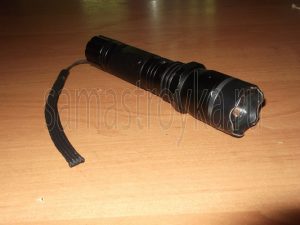
DIY stun gun repair
There can be many reasons for repairing a stun gun with your own hands. The main ones are an inoperative flashlight bulb in a stun gun, an insufficient charge of a stun gun and, strangely enough, the stun gun pierces the body and, accordingly, beats with current where it is not needed.
Immediately it is worth making a reservation at the beginning of the article and saying that repairing a stun gun with your own hands is fraught with unpleasant consequences. You can not only completely break the stun gun, but also get a strong electric shock from it. Therefore, if there are no basic skills in working with devices powered by electricity, then it is better to refuse from self-repairing the stun gun.
Over time, even the best stun gun loses its charge and gradually breaks down. Therefore, if the reason for repairing a stun gun is in insufficient charge or fast discharge, then you should think about the following, first of all:
- Perhaps it's time to change the battery in the stun gun;
- The high-voltage converter of the stun gun is out of order.
And if the first cause of the breakdown of the stun gun is enough to simply eliminate with your own hands, then problems may arise with the replacement of the high-frequency generator in the stun gun.
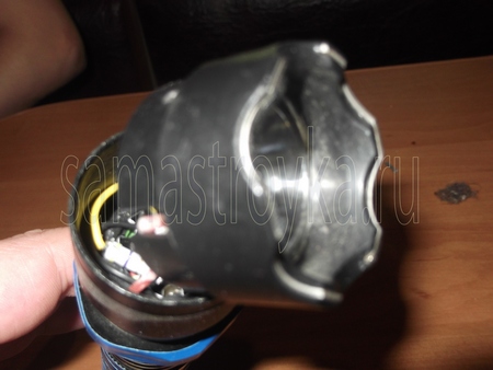
To repair a stun gun with your own hands, you cannot do without knowledge of how a stun gun works. In fact, the operation of a stun gun is quite simple. A charged stun gun holds a charge in the battery or batteries, from which, when the stun gun button is pressed, a constant voltage is applied to the transformer.
From the transformer of the stun gun, an alternating voltage comes out, which goes to the high-frequency converter and voltage multiplier. From the voltage multiplier, the current flows to the external contacts of the stun gun, which are designed to shock the enemy.
If the stun gun is equipped with a flashlight, then if it breaks down, you should first check the light bulb. Depending on the model of stun guns, either a light bulb or an LED can be installed in the flashlight. With the replacement of the LED in the stun gun, certain problems can also arise, because it is, as a rule, non-removable and soldered to a special board.
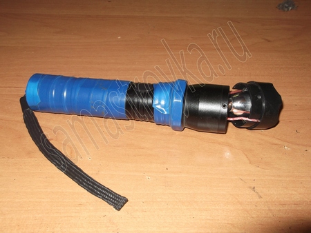
The main thing is, when repairing a stun gun with your own hands, do not forget about safety precautions. A blow over 1000 volts, even if it is short-lived, few people like it. Therefore, before you repair the stun gun, make sure that it is completely discharged.
If this is not the case, then be sure to discharge the stun gun, because only in this way you can not worry about the actual safety when repairing the stun gun with your own hands.
Fig. 1. Stun gun circuit
All parts are not particularly scarce, they can be freely ordered or simply bought at the bazaar. The most critical are the conductors and the spark gap, I advise you to freeze up and find exactly the ones indicated in the parts list. the size of the shocker and the quality of its work depend on them. Everything else you can put whatever comes to hand. Almost any transistors from IRFZ24 to IRL2505 are suitable for the converter. Resistors are also not critical and can differ in one direction or another ..A 3300 peak capacitor is needed to limit the inrush current at the time of start, i.e. to protect the converter. When using fairly powerful transistors (IRFZ44 +), it can be omitted.
There is one interesting feature in the operation of this circuit that some may have already noticed. Namely, when the contacts are short-circuited, for example, when both electrodes are in direct contact with the skin, the correct operation of the shocker is disrupted, because the combat conder does not have time to charge to the required voltage. In this case, this cant is not as important as in multiplier shockers, because the voltage across the capacitor is only about 1000 volts, which is not enough even to break through a thin shirt. Therefore, for simplicity and to reduce the cost of construction, this fact was not paid attention. But still, if you are going to go to war with nudists 😀 THEN YOU SHOULD PUT THE SECOND DISCHARGE GASKET in series with any of the output electrodes of the shocker!
Now a little about the constructive composition of the device. The entire circuit, using the specified parts, is placed on a 40 * 45mm board. The accumulators are 6 pieces of NicD size 1/2 AA, i.e. twice as short as conventional finger-type ones, with a capacity of 300 mAh. Which corresponds to a power of about 15W. They are sold as spare for radiotelephones in the form of blocks of 3 or 4 pieces. The cost is in the region of hundreds of wood per block 😉 Thus, the whole shocker can be made the size of a pack of cigarettes.
The assembly sequence is as follows. To begin with, we refuse to pay, because. anybody in the process will have to re-solder certain details and she will inevitably go there. We take a radiator, for example, from a computer power supply unit and put transistors on it. The radiator must either have insulating gaskets, or then you need 2 separate radiators so that they do not come into contact with each other .. We screw them there and solder everything else right on the weight. Thus, the initial layout should look like a pile of rubbish on your desk 🙂 Do not forget to fix the HV leads at the desired distance (for a start, no more than 15mm), otherwise the transformer and everything else behind it will also burn out.
We turn on the device. Power needs to be taken from those Akum who will later go to the device, all sorts of power supplies and other sources will not work! In principle, the shocker does not require settings and should work immediately. The question is how it will work. With these Akums, the discharge frequency is about 35 hertz. If it is less, there are two possible options, either the transformer is poorly wound, or you used other transistors and you need to choose 330 ohm resistances.
We look at the datasheet for the transit you need, look for the line “INPUT CAPACITANCE” there, the larger the number, the less resistance should be and vice versa. For example, for IRFZ44 it can be 1k, and for IRL2505 no more than 240 ohms. By selection, we achieve the optimal discharge frequency. Next, we begin to separate the output contacts to the estimated distance that you need (for example, I have 25mm). If everything is ok,! We dilute it by another centimeter! and in this state, we do the test for 5 seconds. If everything is ok, we return the previous distance. This stock should be present to the lover, because breakdown of air depends on many factors such as humidity, pressure, etc., so if the distance is "at the limit" at one point the whole structure will go to nothing. For the same reason, 2 diodes are used everywhere instead of one, although everything (seemingly) works fine with one.
If everything worked as it should, you can safely solder the parts into the board and proceed to the next stage.
Since we cannot stamp plastic parts at a factory, and few people have the opportunity to use the factory case, one thing remains - EPOXYDKA. The process is of course painstaking, but it has a number of its advantages. The result is a monolithic block that is not afraid of shocks, water ingress, and is absolutely reliable in electrical terms.For manufacturing, you will need epoxy itself, take a lot of it, thin cardboard from some boxes, a glue gun and some other little things.
The process begins with cutting out the cardboard base, i.e. "view from above". For this, it is very convenient to use a notebook sheet on which you first mark the plan as what will be where it will be, then stick it on a cardboard and cut it out.
Next, prepare strips of cardboard about 3 cm wide, as well as a glue gun.
Now your task is to glue the base around the perimeter with these strips. The process is quite complicated. It is convenient to use long-nosed pliers or tweezers to bend the cardboard. It is imperative to glue from the outside, while making sure the seam is tight.
Place all the main parts inside the body to assess their internal layout. At this stage, you need to determine where the switch and the start button 🙂 will be located, as well as the socket for charging the battery.
Let's apply heat shrinkage. It is very convenient to use it for some sinking of the protruding elements inside. Please note that after pouring, processing will follow and somewhere 2-3mm will be removed on the sides due to cardboard. Also, heat shrinkage allows you to achieve better tightness - the photo shows that it is closed from the outside (it is enough to squeeze it with tweezers while it is hot). At the same stage, you need to connect all the parts together and check the operation of the shocker in this state. As fighting and protective electrodes, I used aluminum rivets, thicker and thinner, respectively. There is a steel rod inside the aluminum, so there should be no problem with soldering, but it is still very convenient to use acid.
Fill in! There is not much to explain here, but keep in mind that epoxy has the property of penetrating wherever it is not needed, so check the tightness before pouring. Have you checked it? now one more time. Then you can start.
Processing stage. After 6-8 hours, when the epoxy is firmly set, it is still quite soft. At this point, you can cut off the excess with an assembly knife, giving the shocker a comfortable shape to hold in your hand. This will not save yourself the need to do further processing with emery and sandpaper, but you will save a lot of nerve cells 😉 After processing, the body can be coated with some kind of varnish, such as a tsapon.
And here's the result! After all, you can enjoy looking at such a thing. Now you can bite the protective electrodes to the desired length if you have not done this yet, and go!
So, the shocker is made, cracks loudly and makes an impression on others 😉 But how can you really check the degree of his anger? At the beginning, we said that it depends on the current in the pulse that the shocker gives. So we will look for it 😉 Below you see a comparison of the discharge from a regular rattle and our device:
It can be seen that the discharge is much thicker, it has a characteristic yellow color and flashes at the edges, which indicates a large current. How big? Let's do a simple test. Take a regular 0.25A mains fuse and place it between the contacts of the shocker so that there is no direct contact. The fuse will burn out. This means that the output current is over 250mA. Compare with fractions of a milliampere in an ordinary shocker 🙂 It is clear that in real conditions, due to the resistance of body tissues, this current will be less, but it will still be TEN TIMES higher than the values for ordinary civilian and even police models!
Information
To leave your comment - register or enter the site under your name.
There are many ways to feel confident in a dark alleyway or narrow, unlit streets, but most are either illegal or time consuming. Not everyone can easily spend 20-30 thousand rubles on a traumatic weapon, and even spend a couple of months on training and obtaining a license. The same applies to martial arts - several years of practicing techniques in the gym does not guarantee protection, and it is impossible to learn how to fight in a month.
One of the best options for protecting yourself and your loved ones from intruders is a stun gun. It does not require a license to carry and is not subject to registration with the Ministry of Internal Affairs, easily fits in a pocket or handbag. Any adult citizen of Russia can buy it, but not everyone can afford it. We will consider one of the many ways how to assemble a simple and powerful stun gun with your own hands, with diagrams and pictures illustrating the creation process.
Homemade stun guns are actually prohibited, since only licensed Russian-made devices are allowed for use on the territory of the Russian Federation. The very fact of owning such a product may attract the interest of law enforcement agencies.
A typical representative of an electrical device for self-defense consists of five components: a battery, a voltage converter, a capacitor, an arrester and a transformer. The mechanism of work is as follows: a capacitor with a certain periodicity discharges the accumulated charge to a transformer, at the output of which a discharge occurs - that same spark. The problem with this design is this transformer, which is created in the factory from special materials according to a secret scheme that cannot be found on the Internet.
Therefore, the circuit will be somewhat different - based on a pair of ignition and combat capacitors. The bottom line is:
- At the push of a button, the igniting capacitor acts in the same way as in the original circuit - it is discharged to the transformer, and that one gives a spark. This spark is an ionized layer of air with much less resistance than normal air.
- at the moment the spark appears, the combat capacitor is triggered, which beats with all the accumulated power through this channel with practically no losses.
As a result, with a lower total power of the product and savings on the transformer, the same, if not angrier, stun gun is obtained, while one and a half times less.
Image from the site
Manufacturing begins with the most difficult thing - a transformer. The reason for this is the difficulty of winding it, so if the assembler cannot bear it and chooses an easier way to obtain a self-defense device (buy it), then no effort will be expended on making the rest of the parts.
The basis will be the B22 magnetic armor core made of 2000NM ferrite. It is called Armor because it is a piece closed on all sides with two leads. It looks like a regular spool, like the one that is inserted into a sewing machine. True, instead of threads, a thin varnished wire with a diameter of about 0.1 millimeters is wound into it. You can buy it on the radio market or get it from an alarm clock. Before starting winding, solder the leads to the ends of the wire to make the structure stronger and more resistant to breakage.
You need to wind it by hand until there is about 1.5 millimeters of free space on the reel. For the best effect, it is best to wind them in layers, insulating them from each other with electrical tape or other dielectric. And if you find a PELSHO wire, then no insulation is required at all - it is already in the wire design: just wind it in bulk and drip a little with machine oil.
After the end of the winding, insulate the turns with a couple of rolls of electrical tape and wind 6 turns of thicker wire (0.7-0.9 millimeters) on top. In the middle of the winding, you need to make a bend - just make a twist and bring it out. It is better to fix the entire wire with cyanoacrylate, and fix the two halves of the coil with each other with cyanoacrylate or electrical tape,
Image from site>
This is the hardest part of making a stun gun with your own hands. Since a standard layer transformer cannot be made at home, we will simplify the structure - we will make it sectional.
As a basis, we take an ordinary propylene tube with a diameter of 2 centimeters. If you still have these after repairs in the bathroom - it's time to use them, if not, buy them in a plumbing store. The main thing is that it is not reinforced with metal. We need a piece 5-6 centimeters long.
It is simple to make a sectional frame out of it - fix the workpiece and cut grooves along its diameter with a width and depth of 2 millimeters every two millimeters. Be careful not to cut through the pipe. After that, cut a groove 3 mm wide along the frame.
Image from my.housecope.com/wp-content/uploads/ext/378
It remains only to make the winding. It is made from a wire with a diameter of 2 millimeters, which is wound on all sections within the tube. Solder the lead to the beginning of the wire and fix it with glue to avoid accidental breakage.
Image from my.housecope.com/wp-content/uploads/ext/378
A ferrite rod with a diameter of 1 centimeter and a length of about 5 centimeters is suitable as a core for a transformer. Suitable material can be found in line scan transformers in old Soviet televisions - you just need to adjust it to size and grind it until it reaches the shape, in fact, a rod. This is a rather dusty job, so you shouldn't do it at home without a respirator. If there is no workshop or garage nearby, use ferrite rings, gluing them together, or buy at the radio market.
Image from my.housecope.com/wp-content/uploads/ext/378
The rod needs to be wrapped with electrical tape and a winding of 0.8 wire is made on it (we used it for the second winding of the transformer of the converter. The winding is done along the entire length of the core, not reaching the edges of 5-10 millimeters, and is fixed with electrical tape.
The core winding is wound in the same direction as the winding on the propylene tube - clockwise or counterclockwise.
After that, insulate the core with electrical tape, but watch out for the diameter - it should fit tightly into the tube. On the side where the winding on the tube does not have a soldered wire, solder the two windings (outer and inner) together. Thus, you will have three conclusions - two ends of the windings and a common point.
If you do not understand the process, you can watch a video on YouTube on how to make a stun gun with your own hands at home.
The final stage is filling with paraffin. Anyone will do - the main thing is not to boil it in order to avoid damage to the internal elements of the transformer. Make a small box slightly higher than the height of the transformer. Place the transformer in it, bring the wires out and fill the exit points with glue. After that, pour the paraffin into the box and put it on the battery so that the paraffin does not cool down, and all the air bubbles come out. We need a headroom due to the shrinkage of the cooling paraffin. Remove excess with a knife.
Image from my.housecope.com/wp-content/uploads/ext/3120
Image from my.housecope.com/wp-content/uploads/ext/378
Now it's time to take a look at the schematic diagram of the stun gun. It looks like this:
- the ignition capacitor is charged through the diode bridge
- the combat capacitor is charged through additional diodes.
Almost any 330 ohm MOSFET transistors are suitable for the converter, the choice of resistors is also uncritical. Capacitors for 3300 picofarad are needed to limit the current when the device is started, that is, to protect the converter. If you are using powerful transistors (like the IRFZ44 +), then this protection is not required. and you can do without installing such capacitors.
There is one peculiarity in the circuit: when the contacts are short-circuited (for example, when touching the skin, not clothes), the shocker does not work correctly, since the combat capacitor does not have time to charge. If you want to get rid of this drawback, put a second spark gap in series with one of the outputs.
The entire circuit (with the correct layout of the elements on the board) fits well on the site of 4 by 5 centimeters. For power supply, we take 6 nickel-cadmium batteries with a capacity of 300 milliampere-hours in the size of half a finger-type battery with a capacity of about 15 watts. Thus, the entire device fits into a package the size of a cigarette pack.
Image from intrashopping.com
Aluminum rivets are the best choice for contacts. They have sufficient electrical conductivity and have a steel core. It provides two advantages at once: the strength of the contacts is significantly increased and there are no problems with aluminum soldering. If they are not there, then ordinary steel plates of any shape will do.
The assembly can be done either on an etched textolite board, or you can solder the elements with wires. But first, it's better to assemble this on a breadboard in order not to waste time and energy on reworking the board in case something goes wrong. High-voltage leads should be fixed at a short distance (about one and a half centimeters) so that the transformer does not burn out.
After unsoldering, turn on the device. Power must be taken directly from the batteries - do not use power supplies. It does not need tuning and it should work immediately after switching on, the frequency of spark formation is approximately 35 hertz. If it is much less, the reason is most likely in an incorrectly wound transformer or in the wrong transistors.
If everything works correctly, then separate the output contacts by a centimeter and start the device again. A standard shocker has a contact distance of 2.5 centimeters. If everything works correctly, then separate the contacts another centimeter and test the device again. If it works well, reduce it back to the standard 2.5 centimeters. Such a power reserve is needed for the device to work in any conditions of humidity and pressure.
If the parts do not smoke or melt, everything is fine, you can solder the elements onto the board and proceed to the last stage - creating the case.
Since stamping the case at home is not available, and 3D printers are not available everywhere and not to everyone, we will use a folk remedy - epoxy resin. Forming such a box is a painstaking process, but this material has a number of advantages:
- solidity;
- tightness;
- electrical insulation.
To create, you will need epoxy itself, cardboard as a frame, a glue gun and some little things.
It is better to start the process by cutting out the back cover of the case from the cardboard with a pre-drawn plan for the location of the parts, and then glue it with strips of cardboard around the perimeter using a glue gun. The strips should be as long as the width of the shocker (about 3 centimeters) plus a margin for the sticker. You need to glue from the outside of the base, while carefully ensuring that the seam is tight.
Image from my.housecope.com/wp-content/uploads/ext/378
After all the strips are glued, place the circuit elements inside and evaluate the correctness of their layout. Also determine where you will have the start button and battery charging connector. If everything suits you, then check the correct connection of the elements with each other and the work of the shocker again. Pay special attention to the tightness of the case - epoxy can penetrate into inconspicuous cracks and leave stubborn stains on any surface.
It's time to start pouring the epoxy into the mold. Set the poured form aside and wait 6-8 hours. After this time, it will not become hard, but it will be flexible enough to give the body the desired ergonomic shape. After complete hardening, sand the epoxy with sandpaper and varnish with any varnish, for example, zapon varnish.
As a result, you get a reliable and durable device that is not afraid of shocks, falls and water. How do I test it? Take a 0.25 amp fuse and place it between the pins. After starting the device, the fuse will burn out - this indicates that the power of the device exceeds 250 milliamperes, which is significant power that can stop even the most zealous and dimensional intruder.
I am sure that everyone reading this article is able to protect themselves and their loved ones from illegal actions.But if they attacked suddenly? And if they are armed with a stun gun?
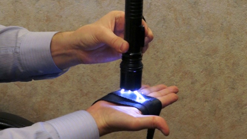
In the article you will find out how quickly do by their by hand high-quality protection against a stun gun / stun gun that will be sewn into a jacket, trousers, coat, gloves. All you need to do is sew the carbon tape into your clothing. The tape is a very good conductor, so electricity will flow through it and not your body.
Do not experiment with electricity on humans or animals! This could result in serious injury or death!

To alter the jacket, it was used 14.5 meters carbon and hot-melt non-woven tape.
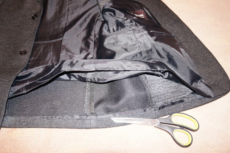
Make a notch at the bottom of the jacket lining.
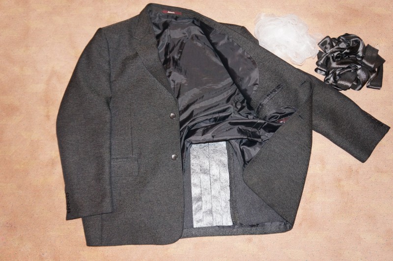
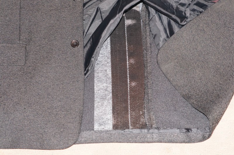
We put stripes on the jacket non-woven (white) and carbon (black) tape. Let’s iron it all iron.
It is convenient to work with the tape if you cut it into small pieces and lay them like a mosaic on a jacket. Place ribbons as close to each other as possible to avoid gaps in "protection".


Step by step we will cover the entire surface of the jacket with carbon tape. Turn out the sleeves and fasten the tapes on the seamy side.

Carbon fiber is a monotone material. He not is burning and not colors clothes.
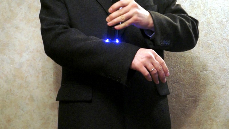
Sew on the lining. Everything is ready!
Note: The defense after extreme testing showed its weakness. For testing the jacket, a more powerful stun gun with a voltage of 800 yew v. Two metal needles pierced the carbon tape. The tension on the needles was 150 in... This value is palpable for the human body. You can increase the thickness of the carbon tape for added protection.
Good luck in job. Take care of yourself and your loved ones.
- ATTENTION! Need BrainHelp! - 08.11.2017
- Ideal solution for a Halloween party - 10/31/2017
- Limited Edition: Black Lemonade - 10/31/2017
- Isaac Clark's budget helmet from the "Dead Space" universe - 10/29/2017
- Dinner Party at Bruce Wayne Estate - 10/28/2017
- Who is hiding behind the carnival mask? - 27.10.2017
- From a smile, a gloomy day is brighter ... - 10/26/2017
- How to overcome fear of the stranger? - 10/25/2017
- Get the most out of your drilling machine - 10/24/2017
- Becoming a knight is absolutely easy! - 23.10.2017
- Fantastic story about the crown of the elf queen - 21.10.2017
- 45 profitable home production business ideas part 2 - 10/19/2017
- 10 professional woodworking tricks - 10/18/2017
- Homemade products for Halloween (Brain 2017) - 10/17/2017
- 45 profitable home production business ideas part 1 - 10/17/2017
And if they poke into unprotected areas of the body? And then, what is now all the clothes to alter, or to wear the same jacket in winter and summer?
And how will they know that there is no protection there? If there is a desire and material, then you can alter ...
gorgeous. each and every one of the
Your browser doesn’t support canvas.
| Video (click to play). |

