In detail: do-it-yourself repair of an epra 4x18 from a real master for the site my.housecope.com.
The ballast for the discharge lamp (fluorescent light sources) is used to ensure normal working conditions. Another name is a ballast (ballast). There are two options: electromagnetic and electronic. The first of them has a number of disadvantages, for example, noise, the effect of flickering of a fluorescent lamp.
The second type of ballast eliminates many disadvantages in the operation of a light source of this group, and therefore is more popular. But breakdowns in such devices also happen. Before discarding, it is recommended to check the elements of the ballast circuit for faults. It is quite possible to independently repair electronic ballasts.
The main function of the electronic ballast is to convert alternating current into direct current. In another way, the electronic ballast for gas discharge lamps is also called a high-frequency inverter. One of the advantages of such devices is their compactness and, accordingly, low weight, which further simplifies the operation of fluorescent light sources. And also the electronic ballast does not create noise during operation.
The electronic ballast, after connecting to the power source, provides current rectification and heating of the electrodes. In order for the fluorescent lamp to light up, a voltage of a certain magnitude is applied. The current is adjusted automatically, which is realized by means of a special regulator.


For the intended purpose, the following types of electronic ballasts are found:
- for linear lamps;
- ballast built into the design of compact fluorescent light sources.
Electronic ballasts for fluorescent lamps are divided into groups that differ in functionality: analog; digital; standard.
| Video (click to play). |
The ballast is connected on the one hand to the power source, on the other - to the lighting element. It is necessary to provide for the possibility of installing and fixing electronic ballasts. Connection is made in accordance with the polarity of the wires. If you plan to install two lamps through a ballast, the parallel connection option is used.
The diagram will look like this:

The ignition and maintenance of the functioning of the lamp is carried out in three stages: the heating of the electrodes, the appearance of radiation as a result of a high-voltage pulse, the maintenance of combustion is carried out by means of a constant supply of a small voltage.
If there are problems in the operation of gas discharge lamps (flickering, lack of glow), you can make repairs yourself.But first you need to understand what the problem is: the ballast or the lighting element. To check the operation of the electronic ballast, a linear lamp is removed from the luminaires, the electrodes are closed, and a conventional incandescent lamp is connected. If it lights up, the problem is not with the ballast.
Otherwise, you need to look for the cause of the breakdown inside the ballast. To determine the malfunction of fluorescent lamps, it is necessary to "ring" all the elements in turn. You should start with the fuse. If one of the circuit nodes is out of order, it is necessary to replace it with an analogue. The parameters can be seen on the burnt element. Repairing HID ballast requires the use of soldering iron skills.
If everything is in order with the fuse, then the capacitor and diodes that are installed in close proximity to it should be checked for serviceability. The capacitor voltage should not be below a certain threshold (this value differs for different elements). If all the control gear elements are in working order, without visible damage and the ringing also gave nothing, it remains to check the choke winding.
In some cases, it is easier to buy a new lamp. It is advisable to do this in the case when the cost of individual elements is higher than the expected limit or in the absence of sufficient skills in the soldering process.
Repair of compact fluorescent lamps is carried out according to a similar principle: first, the case is disassembled; the filaments are checked, the cause of the breakdown on the control gear board is determined. There are often situations where the ballast is completely functional and the filaments are burned out. In this case, it is difficult to repair the lamp. If there is another broken light source of a similar model in the house, but with an intact incandescent body, you can combine the two products into one.
Thus, the electronic ballast represents a group of improved devices that ensure the efficient operation of fluorescent lamps. If the light source flickers or does not turn on at all, checking the ballast and then repairing it will extend the life of the light bulb.
One, the transistor rarely burns. Usually, the second, as well, turns out to be scorched and (or) punctured (cut off) diodes (when one, and when all 4) of the rectifier.
At the same time, the breakdown of the transistor pulls the burnout of the resistors in the base and (if they are) in the emitter circuit of the transistors.
In general, the repair of electronic ballasts, first of all, consists in checking the serviceability of ALL of its elements. Fortunately, there are not many of them, and everyone “calls” without watering.
I also don’t know a transistor like yours.
But, as a rule, the type MJE13001 (3, 5) or similar are used.
These transistors are quite common, so if you take them, you won't be mistaken. I recommend changing a couple at once.
Datasheets for these transistors are easily found on the network.
Therefore, it will not be difficult to decide.
With the power of your LDS of 15W, the MJE13001 is quite enough. With the correct setting of the inverter, they should not even get warm.
You can supply with a margin - MJE13003.
The question remains, why did your electronic ballast burn out?
If the reasons are not obvious (took, and burned out), then you need to take measures - be sure to put a resistor, about 10 Ohm at the input of the electronic ballast. That is, supply 220V power to the electronic ballast through this resistor.
Well, once we got into the circuit, it’s a sin not to improve it by increasing the capacity of the electrolytic capacitor of the filter to 10 μF, and installing either a posistor in parallel with the LDS, or a 100-700 Ohm thermistor in series with the resonant capacitor of the circuit.
It is very useful to measure the operating modes of the LDS, oscillograms of its current and voltage, as well as the currents of transistors.
After that, your electronic ballast will have a chance to work, at least until the LDS resource is consumed.
It is a well-known fact that lamps with fluorescent lamps are widespread not only in industries and organizations, but also in private houses and apartments. Surely every second person in the garage or pantry has an old, dusty similar lighting device that no longer works, but it’s a pity to throw it away. Then why not repair these lamps with your own hands? Moreover, if there is an opportunity to find somewhere old and useless lamps, the repair will not cost a penny, but we will figure out how to repair it.
The main thing that you need to know before you start repairing fluorescent lamps is how they work.
You can understand the principle of operation of a fluorescent lamp using the example of the schematic image below.
- ballast (stabilizer);
- a lamp tube including electrodes, gas and phosphor;
- phosphor layer;
- starter contacts;
- starter electrodes;
- starter housing cylinder;
- bimetal plate;
- filling the flask with inert gas;
- filaments;
- ultraviolet radiation;
- breakdown.
A layer of phosphor is applied to the inner wall of the lamp in order to convert ultraviolet light, which is invisible to humans, into light for normal vision. When you change the composition of this layer, you can change the color tint of the lighting fixture.
So, knowing the design of the lamp and the luminaire circuit, you can begin to restore it.
The first step is to check if there is a malfunction in the fluorescent lamp using a tester or multimeter. It must be remembered that in the circuit, for example, of an Armstrong lamp with an electronic ballast for 4 lamps (4 x 18), when one burns out, all four will not work. In devices with one starter for 2 tubes, both must be in good working order, but when connected with a starter, one working lamp is enough for each lamp, and the lamp will work even if the second is faulty.
After energizing, if the luminaire is not lit, you need to check the voltage supply to it. This can be done from the input terminal strip.
So, if the previous steps are completed, and the lamp still does not work, you need to start checking all the nodes of the lighting device circuit, that is, directly start repairing fluorescent lamps.
A visual inspection can tell a lot, sometimes with the naked eye you can see breakdowns, dents and other reasons why the lamp does not light up.
As with any repair, you first need to check the elementary. It makes sense to change the starter to a known working one, after which the lamp should light up, and then this malfunction of the fluorescent lamp can be excluded. However, a starter that is suitable in terms of parameters may not always be at hand, and it is somehow necessary to check the one that is, what if the reason is not in it?
Everything is simple enough. You will need a regular lamp with an incandescent light bulb. Power must be supplied to it like this - turn on the sequentially checked starter into the break of one of the wires, and leave the second intact. If the lamp lights up or blinks, then the device is operational and the problem is not in it.
Next, we check the input and output voltage at the choke. When working, the tester should show the output current. If necessary, this circuit assembly must be replaced.
If, after that, the lamp does not light up, then you will have to ring all the lamp wires for integrity, and also check the voltage at the contacts of the cartridges.
Here, the repair of a fluorescent lamp is reduced only to checking the lamps, the integrity of the wiring and the holder-holders. If they are in order, you just have to replace the electronic ballast.
Of course, if a person knows how to check the electronic ballast elements for serviceability, and there is even a little knowledge in radio electronics, then it will not be difficult to fix the electronic ballast.
Most often, if the electronic ballast (ballast) fails, then the transistor is to blame for this, which can sometimes be seen with the naked eye. If it is impossible to visually determine this, you will have to remove the transistors from the circuit and ring with a multimeter.
If they are in good working order, then the resistance in them will be 400-700 ohms. If one of the transistors is burned out, automatic combustion of a 30 ohm resistor is also possible.
There is also another weak point in the circuit - a low-impedance fuse of 2-5 ohms. Very rarely, the reason may be in the burnt out elements of the diode bridge. These are all possible reasons, after their elimination, the ballast repair will be completed, that is, the restoration of the burnt out electronic ballast.
The repair of fluorescent lamps has its own little tricks. For example, an urgent need to start a similar lighting device, and the starter is out of order, and there is no way to replace it. By itself, this element of the circuit serves to warm up the filaments in the fluorescent tube.
But what if, for example, the throttle is out of order? In our time and in stores, it is not possible to find it in all.
It is quite possible to prolong the operation of a burned-out light device. There is a way in which you can turn on a fluorescent fluorescent lamp without a choke and a starter (connection diagram in the figure). Of course, this method is not suitable for everyone; you need at least a little understanding of electrical engineering.
Voltage is applied after short-circuiting the filaments. The rectified voltage becomes twice as large, which is quite enough to start the lamp (in theory, this function is performed by the choke). Capacitors C1 and C2 (in the diagram) must be selected for 600 V, and C3 and C4 - with a nominal voltage of 1000 V. After some time, mercury vapors, of course, will settle in the area of one of the electrodes, and the light from the lamp will become much less bright. It will be possible to get rid of this simply by changing the polarity, i.e., simply by deploying the reanimated burned out LL.
There are lighting fixtures that are designed exclusively for operation without a starter. These lamps are marked with RS. If such a tube is installed in a luminaire equipped with a breaker, the lamp burns out very quickly. This is due to the need for a longer time to warm up the spirals of such fluorescent tubes. The durability of the starter is small, it often burns out, and therefore it makes sense to consider the possibility of how to turn on the fluorescent lamp without it. This will require the installation of secondary transformer windings. If you remember this information, then the question will no longer arise how to light a fluorescent lamp if the starter burns out (connection diagram below).
Thus, you can even assemble a fluorescent lamp with your own hands at no extra cost.
Therefore, the conclusion suggests itself - there is no need to throw away something that is completely maintainable and viable. You just need to think well with your head, and then work with your hands, and a lit lamp will not only add confidence in your abilities, but also have a good effect on your financial condition. And nowadays, the money saved on the lamp can be invested in more necessary things.

Fluorescent lamps (abbreviated as LDS) have occupied a worthy niche in the electric lighting market due to their efficiency and high performance.
Various modifications of LDS have appeared, which make it possible to improve lamp starting devices (electronic ballasts), minimize the size of lamps, make compact fluorescent lamps (CLS) by combining a bulb and an electrical board in one housing.
These lighting electrical appliances are significantly more expensive than conventional incandescent bulbs, therefore, if fluorescent lamps fail, you should think about their repair and restoration.
The principle of operation of fluorescent light sources, their connection and replacement are described in detail in the previous article, and you can learn about the types, advantages and benefits of fluorescent energy-saving lamps by clicking on this link. Here, the main problems of fluorescent lamps, methods of extending the service life of the LDS and the possibility of repairing ballasts (ballasts) will be described.
It is worth briefly describing the interaction of the components of a fluorescent lamp - the lamp itself cannot work without a ballast, which is electromagnetic (EMPRA) in the form of a throttle and a starter, and electronic (Electronic ballast), in which the physical conditions for the launch and glow of the light source are provided by electronic components.
Osram electronic ballast for fluorescent luminaires
Accordingly, the cause of an inoperative lamp can be malfunctions, both in the electronic circuit of the ballast, and aging, wear and tear of the lamp itself. Correct determination of the reasons will allow you to repair an idle fluorescent lamp with your own hands.
Unlike conventional incandescent bulbs, which stop working (burn out) instantly and always unexpectedly, the rapid wear of a fluorescent lamp can be determined by how it blinks (blinks) during startup. This process indicates changes in the chemical composition of the glowing gas (degeneration of mercury vapor) as well as the burnout of the electrodes.
As a rule, a daylight lamp blinks, at which blackening is observed from the ends - this carbon deposit indicates a burnout of the spiral and irreversible chemical processes occurring inside the bulb - such a light source cannot be repaired, but its service life can be extended.
Very often the fluorescent lamp blinks due to malfunctions in the electronic ballast or electronic ballast. Replacing the lamp with a new one will help pinpoint the cause of the blinking
But don't throw away your old lamp. First, it must be disposed of in accordance with state laws, as there are harmful mercury vapors inside the flask.
Secondly, even if the filaments are burned out, you can extend the operating lines of this light source using a simple circuit that you can solder with your own hands, or by connecting the lamp to an electronic ballast with a cold start, closing the contact terminals, as shown in the video:
For a similar reason, the fluorescent lamp blinks at the start due to low mains voltage. During operation, if the voltage surges do not exceed the permissible limits, a working daylight lamp should not blink - the ballast maintains the current in the gas at the same level.
Blackening at the ends of the lamp indicates a loss of emission, which leads to blinking at startup, unstable operation and a weakening of the glow
The algorithm for repairing a flashing daylight lamp occurs in stages:
- The mains voltage and the quality of the connection contacts are checked;
- The lamp is being replaced with a serviceable one;
- If the lamp blinks further:
- in lamps with electronic ballasts, you need to change the starter and check the throttle (ballast);
- in daylight sources with electronic ballasts, repair or replacement of electronic ballast is necessary;
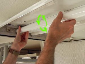
Replacing a lamp as the easiest way to diagnose a luminaire
Checking and repairing ballasts, as well as extending the life of a worn-out lamp, requires radio engineering knowledge and appropriate tools, such as a multimeter, a soldering iron, a set of screwdrivers, etc.
Since a fluorescent lamp with an electronic ballast is quite simple, after replacing the lamp and starter, the repair algorithm consists of the following steps:
-
Check capacitors that are used to reduce electromagnetic interference and compensate for reactive power losses. Sometimes, although rarely, the fluorescent lamp blinks due to current leaks in faulty capacitors, so it is worth excluding this cause before changing the relatively expensive choke.
Chokes for fluorescent luminaires
Electronic circuits differ for different manufacturers of electronic ballasts, but, in general, their principle of operation is the same - the filaments of fluorescent lamps have a certain inductance, which allows them to be included in an auto-oscillating circuit consisting of capacitors and coils. This circuit has a feedback with an inverter assembled on powerful transistor switches.
Typical circuit of an electronic ballast for two fluorescent lamps
When the filaments are heated, their resistance increases, the characteristics of the oscillations change, to which the inverter reacts, giving out the lamp ignition voltage. The current through the ionized gas shunts the voltage across the filaments, reducing their glow. The feedback of an inverter with a self-oscillating circuit allows you to adjust the current in the lamp.
A diode rectifier with a filtering and noise reduction system is used to power the inverter. The high-frequency inverter is one of the reasons for the great popularity of electronic ballasts - the connected lamp does not blink at twice the mains frequency of 100 Hz, and does not hum during operation, as is the case when using electronic ballasts.
Most radio amateurs are not set out to understand the purpose and function of each element of the circuit, especially if it is not possible to check the characteristics in operation. Therefore, it will be much more useful to describe the sequence of actions during the repair.
To diagnose electronic ballasts in repair shops, an oscilloscope, frequency generators and other measuring equipment are used. At home, the ability to find faulty components is reduced to a visual inspection of the electronic board and a sequential search for a burned-out part using the available measuring tools.
Troubleshooting the electronic ballast board
The first step is to check the fuse, if it is present in the circuit. Failure of the fuse may be the only problem caused by overvoltage in the network. But more often a blown fuse, as a rule, indicates more complex malfunctions of the fluorescent lamp control gear.
As practice shows, in electronic ballast any components can fail - capacitors, resistors, transistors, diodes, chokes and transformers. You can visually identify the malfunction by the characteristic blackening of parts, discoloration of the board or swelling of capacitors, as shown in the video:
For checking parts with a multimeter (especially transistors and diodes), they are better evaporate from the board - the resistance of other elements of the circuit can give false readings. Without desoldering the parts, they can be guaranteed to be checked only for breakdown. When checking parts, there may be a problem with their identification, therefore, it will be useful for repairs to download the device diagram first.The identified defective element must be replaced. Soldering semiconductor devices - diodes and transistors should be done with extreme caution - they are sensitive to overheating. It should be remembered that it is impossible to start the electronic ballast without load, that is, you need to connect a fluorescent lamp of the appropriate power to it.
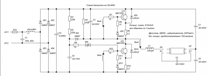
Many radio amateurs are switching from EMPRA, making homemade electronic ballast for fluorescent daylight sources. The diagram of the electronic ballast with the oscillograms measured at the control points is shown in the figure:
Electronic ballast circuit
The figure below shows the oscillogram at the time of starting (lighting up) the fluorescent lamp, as well as a drawing of the printed circuit board and the appearance of the electronic ballast.
Ballast printed circuit board, its appearance and oscillogram at the time of starting the lamp
In the video below, the master who made this electronic ballast indicates the main features of the hand-made manufacture of this device:
Already during the beginning of the mass operation of fluorescent lamps, radio amateurs learned to extend their service life and forced fluorescent lamps to light up, in which the incandescent filaments had burned out. Ignition was provided by increasing voltageapplied to the lamp electrodes.
The voltage increase is carried out according to the scheme with a full-wave multiplier on diodes and capacitors. Thus, at the moment of start-up, a voltage peak of more than 1000 V is reached at the lamp electrodes, which is sufficient for cold ionization of mercury vapor and a discharge in the gas of the bulb. Therefore, ignition and stable operation of the lamp is possible, even with burnt-out spirals.
The ratings of the lamp starter components are shown in the table below.
The main disadvantage of this circuit for starting fluorescent lamps is the high rated voltage of the capacitors - at least 600 Vwhich makes the device quite bulky. Another disadvantage is direct current, due to which mercury vapor will accumulate near the anode, so the lamp will need to be switched periodically by removing it from the holders and wrapping it.
The resistor acts as a current limiting function, otherwise the lamp may explode. The resistor can be wound with your own hands using nichrome wire, but the same results are obtained with a properly selected incandescent lamp, in which the dissipated thermal energy will not be wasted, but will be emitted in the form of an additional glow of the light bulb.
In most cases, radio amateurs use a 127 V incandescent lamp with a power of 25-150 W instead of a resistor, combining them if necessary. The power of the lamp connected instead of the resistor must be several times higher than the power of the connected fluorescent lamp. The ratings of other elements, calculated based on the power of the fluorescent lamp, are shown in the table.
Ratings of components of the device for starting burned-out fluorescent lamps
In this table, the required resistance and power of the diffusing lamp is achieved by connecting several 127 V lamps in parallel. The diodes can be replaced with imported ones with similar characteristics. Capacitors must withstand a voltage of at least 600 V.
The need for good lighting of an amateur radio place of employment, with a sufficient luminous flux and at the same time economical, prompted, one might even say, some searches and a test of options. First I used an ordinary small lamp with a clothespin, changed it to a small tabletop fluorescent lamp, then there was an 18-watt "ceiling-wall" fluorescent lamp made in China. I liked the latter most of all, but the fastening of the lamp itself in the fittings was somewhat underestimated, literally by two or three centimeters, but they were not enough "for complete happiness". I found a way out to do the same, but in my own way. Since the operation of the existing electronic ballast did not cause any complaints, it was logical to repeat the circuit.
This is a large part of this electronic ballast, the choke and capacitor from the Chinese were not included here.
Actually, a diagram copied from a printed circuit board in good faith. The nominal value of the electronic components allowing this to be done was determined not only "by their appearance", but also by measurements, with preliminary desoldering of the components from the board. In the diagram, the value of the resistors is indicated in accordance with the color coding.Only in relation to the choke, I allowed myself not to unwind the one available to determine the number of turns, but measured the resistance of the wound wire (1.5 Ohm with a diameter of 0.4 mm) - it worked.
The drawing can be saved to a PC and enlarged
First assembly on a circuit board. I carefully selected the component ratings, regardless of the size and quantity, and was rewarded - the light came on the first time. Ferrite ring (10 x 6 x 4.5 mm) from an energy-saving light bulb, its magnetic permeability is unknown, the diameter of the wire of the coils wound around it is 0.3 mm (without insulation). The first start on a mandatory basis through a 25 W incandescent light bulb. If it is on and the luminescent initially blinks and goes out, increase (gradually) the C4 rating, when everything worked and nothing suspicious was found, and removed the incandescent lamp, then reduced its rating to its original value.
To some extent focusing on the printed circuit board of the original source, I drew a signet under the existing suitable case and electronic components.
I etched a handkerchief and assembled a diagram. I was already looking forward to the moment when I would be pleased with myself and glad to be. But, the circuit assembled on the printed circuit board refused to work. I had to delve into and engage in the selection of resistors and capacitors. At the time of installation of the electronic ballast at the site of operation, C4 had a capacity of 3n5, C5 - 7n5, R4 resistance 6 Ohm, R5 - 8 Ohm, R7 - 13 Ohm.
The lamp "fit" not only into the design, the lamp, raised all the way up, made it possible to comfortably use the shelf inside the secretaire niche. Babay brought coziness in the "room".
Dear site visitors.
Sometimes such a malfunction occurs, after installing and connecting a luminaire with two fluorescent lamps, the luminaire is working properly. Several months pass and the lamp starts to turn on with one lamp. You start scrolling the lamp in sockets, change the starter, but there is no result. What to do and how to be, how to repair a lamp with fluorescent lamps yourself?
To begin with, consider the schemes of such lamps with fluorescent lamps:
- two fluorescent lamps;
- two starters;
- one choke;
- capacitor.
The fluorescent lamp has two filament spirals. Lamps, starter and choke are connected in series in the electrical circuit. The capacitor is connected in parallel.
- capacitor;
- two starters;
- two fluorescent lamps;
- two chokes.
The connection of fluorescent lamps in Fig. 2 does not differ in any way from the connection diagram of the lamps in Fig. 1. Two wires, phase, zero have a branch in this circuit.
And the simplest circuit of a luminaire with one lamp is shown in Fig. 3, where the capacitor, lamp and starter in the circuit are connected in parallel. The choke is connected in an electrical circuit - in series.
Similar lamps are found with three lamps. The very essence of the matter is not in this, - not in the number of lamps.
The reasons for not turning on a luminaire with one lamp or a luminaire consisting of two or more lamps, when one of the lamps of the luminaire does not turn on, may be as follows:
- malfunction of the lamp itself;
- no contact with the throttle;
- no contact with the starter;
- break in the wires.
The electrical circuit of the luminaire and establish exactly where the break is located - you can check with a probe. After you have purchased the luminaire, check all the contact connections of the luminaire.
Practical example. In the room, an electrician completely carried out the installation and connection of fluorescent lamps with two lamps, after a certain time some lamps began to work with one lamp. When I began to check the contact connections of the lamps, the reason was the following - an unreliable contact connection of one of the wires with the choke. Where there was no contact with the throttle, the lamp did not turn on.
Repair of fluorescent lamps - with electronic ballast
Armstrong fluorescent ceiling recessed luminaires with electronic ballast are simple in design and convenient in that they do not require any effort during removal and installation.
recessed ceiling lamp Armstrong
electronic ballast power supply FINTAR
Here is an example from my own practice. It was necessary to fix the malfunction of the Armstrong recessed ceiling lamp.
For this, the luminaire had to be removed from the ceiling and the electrical connections had to be checked. As a result of the diagnostics, it was found that the electronic elements of the FINTAR electronic ballast are out of order - they have burned out.
It was such a power supply unit that was not on sale; I had to purchase another similar electronic ballast for a lamp for four fluorescent lamps - Navigator.
electronic ballast Navigator
If you look closely at the two power supplies, the wiring diagrams for the fluorescent lamps are different.
The question arises: How to connect the fluorescent lamps of the ceiling lamp to another power supply?
In this example, the wire connections to the fluorescent lamp holders only need to be made according to the electrical diagram of the newly installed power supply.
Accordingly, the circuit of the contact connections of the wires had to be redone, cut off in one place, and build up the wire in another. When changing the connection diagram, the wires are pre-twisted and insulated with insulating tape.
After all the connections have been made and after making sure that when the luminaire is connected to an external source of electrical energy, the socket - all four fluorescent lamps light up - the insulating tape is removed at the place of wire connections.
A piece of cambric is put on one of the wires. The connected copper wires are etched with soldering acid and then a small layer of tin is applied to the junction with a soldering iron, soldering the wires.
etching of wire connections with soldering acid followed by soldering
soldering connected wires
Further, after the soldering of the two wires is completed, a cambric is put on the junction instead of an insulating tape.
insulation of wire connections with cambric instead of insulating tape
This method of connecting wires with subsequent insulation with cambric is simpler and more reliable. If you connect two wires simply in a twist without soldering and then insulate with an insulating tape, the connection will subsequently undergo oxidation and heating of the wires.
Numbering of contact connections of wires with electronic ballast - goes from top to bottom. That is, the first and second contact wire connection must correspond to the connection of two fluorescent lamps on one side, and so on. When connecting, you need to carefully look at the electrical diagram of the power supply and follow the given execution of such connections.
contact connection of wires to the electronic power supply electronic ballast
A small layer of tin is also applied to the ends of the bare wires before connecting to the electronic power supply unit, for a high-quality connection.
In general, there is nothing complicated here, and you can easily eliminate such a malfunction.
Date: 16.09.2015 // 0 Comments
Continuing the topic of fixing fixtures, many will find it useful to know not only how to check a fluorescent lamp, but also how to check the ballast of a fluorescent lamp. For a quick check, a minimum of devices are needed: a control light, a wire, a couple of paper clips, as well as a few minutes of free time.
First, you need to present a diagram of the electronic ballast of a fluorescent lamp and add a control lamp (indicated by red lines) to its design.
Most luminaire circuits are almost identical to each other, differing only in minor changes.
In general terms, before checking the electronic ballast for fluorescent lamps, you need to remove the tube, then short-circuit the leads of the filaments, and then connect a regular 220 V low power incandescent light bulb between them.
Attention! To avoid the failure of the electronic components of the ballast, it is not recommended to connect the circuit with no load to the network, i.e. without a bulb.
For simple lamps, it is very convenient to use a paper clip, it reliably closes the contacts going to the tube.
After all the manipulations, such a structure can be included in the network. The working ballast will be able to supply voltage to the light bulb, and as you can see from the photo, it will glow.
If the ballast was repaired with your own hands, and you need to check its performance, it is best to connect another light bulb in series with the lamp. In the event of errors made in the work, or a short circuit, this light will glow brightly, and the circuit components will not fail.
In this article I will tell you the common breakdowns of modern "ballasts" of fluorescent lamps, how to repair them, I will give analogs of radio components that can be used for repair. Because These lamps are still quite common in everyday life (for example, I use 5 such lamps every day), I think the topic is more than relevant.
If your fluorescent lamp stops shining, the first step is to replace the fluorescent "bulb" itself. It may have two malfunctions: failure of one of the channels (breakage of the heating coil) or the banal "aging" effect.
If in the dark on a switched on lamp there is a barely noticeable glow of the filaments, then, most likely, the breakdown of the electronic "ballast" consists in the breakdown of the capacitor connecting the filaments (see Fig. Item 2). Its capacity is 4.7n, working voltage is 1.2kV. It is better to replace it with the same one, only with an operating voltage of 2kV. In cheap ballasts, there are 400 or even 250V capacitors. They are the first to fail.
When the actions from the previous paragraph did not help, you need to start checking the radio components with the fuse in the diagram. It is often available, but I do not have it on the board (see Fig. Item 1).
The next thing to pay attention to is transistors (see fig. Item 1). They can fail due to power surges, for example, if there is a relay voltage stabilizer at home, or often you or your neighbors use welding. These replacement transistors can be found in power supply units for energy saving lamps. Because such lamps often fail due to bulb breakdowns, then the circuit and, accordingly, the transistors, remain working.
If there are no such lamas, then you can replace the transistors with analogs. Analogs of transistors 13001, 13003, 13005, 13007, 13009 are shown in the table below. The most popular replacements are analogs such as KT8164A and KT872A.
Sometimes you need to ring the rest of the radio components and replace them, if damaged are found. After each stage of repairing the ballast of fluorescent lamps, it is recommended to turn them on for the first time through a 40-watt incandescent lamp connected in series. By its glow, you can see the presence of a short circuit.
It is important to remember that modern electronic ballasts are impulse devices, which are strictly prohibited to be switched on without load (in our case, a fluorescent lamp), because this will lead to their failure.

Video (click to play). If you have tried everything, but nothing has helped, or there is no desire to tinker with the ballast, then you can use a switching power supply from an energy-saving lamp. It is so small that it fits easily in some fluorescent lamp housings. In this case, the filaments of the fluorescent lamp are connected to the contacts on the board, where the contacts of the bulb of the energy-saving lamp were connected. The wattage of the power supply should roughly match the wattage of the lamp. Personally, I have a 36W fluorescent lamp powered by a power supply from a 32W lamp.

