In detail: do-it-yourself repair of a hair dryer fe 2000e from a real master for the site my.housecope.com.
I have sent you a disassembly diagram and an electronic circuit.
As for the diode, I can't help - I'm not an expert, but I think I need to look at the parameters.
[QUOTE] Andrey Alyoshintsev writes:
Sergey, you do not know what kind of solution (possibly ceramics + quartz)? [/ QUOTE]
Unfortunately no. I'll try to find out tomorrow.
[QUOTE] Andrey Alyoshintsev writes:
And if you put a quenching capacitor? [/ QUOTE]
The heater should not burn at all. Probably something else on the control board is faulty?
[QUOTE] Andrey Alyoshintsev writes:
Wound nichrome with a stretch [/ QUOTE]
Apparently this was the problem - the heater threads came too close to each other.
Successful and long-term work of your instrument.
Answered by email.
Yes, the likelihood of a service appearing in a city with a population of less than 50,000 is still low.
Have you looked at the nearest cities?
Tomorrow I will discuss with the DSO what to do in this case.
If there are basic concepts in electronics and there is a tester, then the malfunction is easy to find.
If there were such, then there would be no questions
Hello! Podskite what may be the hair dryer Interskol FE-2000 the spiral is heating up, and the engine does not work in any position, when I put the regulator in the last position and the switch is also just buzzing inside. I opened the visually burned out nothing. Please can anyone come across answer the box
The hair dryer has two spirals, one main, large, the other auxiliary, small.
Most likely, you see how the big one heats up, and the little one is cut off, so the engine does not spin.
Check out the spiral.
Here is a similar problem and how I solved it.
| Video (click to play). |
measured the voltage. one probe on the common + capacitor and the other on the red and green ends of the wires.
everywhere 19.4V.
the extinguishing resistance was torn in one place. I put some tin on the gap.
everything worked, but now I think either the tin will bounce off, or break in any other place. squishy design.
is there a way to power the engine differently? can there be more reliable extinguishing resistance? there is nowhere to sculpt a separate transformer.
in any case, thanks to everyone who responded!
ps after 3 minutes of work, my soldering fell off. Still, how to make it more reliable?
Good day everyone! Please tell me what could be the reason for the breakdown of the FE-2000 hair dryer on the DB230V board - the spirals are heating up, but the fan is silent! 
buy bosch)) I have been working for 2 years already)
hand over for diagnostics, they will say there)
alex_g wrote:
Good day everyone! Please tell me what could be the reason for the breakdown of the FE-2000 hair dryer on the DB230V board - the spirals are heating up, but the fan is silent!
there is a motor, it seems, at 6V constant. It is powered by an alternating voltage removed from a part of the spiral and rectified by diodes. although I can confuse something - there is also a seven-story regulator in the spiral circuit. thermal fuse. to disassemble laziness. put a photo.
volodrez wrote:
there is a motor, it seems, at 6V constant. It is powered by an alternating voltage removed from a part of the spiral and rectified by diodes. although I can confuse something - there is also a seven-story regulator in the spiral circuit. thermal fuse. to disassemble laziness. put a photo.
You are absolutely right! I found the reason: that very spiral has burnt out or burst - the small one, but the big one - it’s warming up! 

alex_g wrote:
how to rewind it correctly, without having an electrical engineering education ?!
Well, is there even a multimeter? and it should itch in a certain place and not let you sleep peacefully. Then it will go.
since we have disassembled it. in general, restore the spiral is a trifling matter - it's not to rewind the rotor.
18 volt dc motor
And the diagram and photo are here ”>
on the DB230V board
found a topic! The same FIT hair dryer is inexpensive but I want to repair it myself. I want to put a transformer from charging a mobile with an iron core, but how many turns to wind and how thick the wire is not to understand. Please respond if anyone is interested.
phiopent wrote:
.want to supply a transformer from charging a mobile phone with an iron core
the spiral is burnt out! instead of her. I tried to connect the motor from charging the screwdriver, but it works but there is a big trance. I want to shove a trance inside the hair dryer.
phiopent wrote:
the spiral is burnt out! instead of her. I tried to connect the motor from charging the screwdriver, but it works but there is a big trance. I want to shove a trance inside the hair dryer.
but the part of the spiral from which the power of the motor is taken is also used for heating. If you exclude it, you will get more intense heating, and the burnout of the protective thermal fuse, if it is still installed
.but if not, then the spiral itself. in general, there are many options for you. to buy a hairdryer in the Ribbon -399r, order a heater 03.04.01.01.00 (search in Google) also 300 rubles + shipment. wind the spiral yourself and connect it by pressing (I do I did, such small sleeves are sold). I would not wind a small transik for many reasons. I should disassemble my hair dryer, but higher
alexan17 wrote:
18 volt dc motor
I didn't find it in Google about the voltage. But I would look in the direction of pulse chargers or use an electronic transformer for halogen lamps, with a slight modification, their advantages are small in size and lightness, if there is nowhere to put it inside, you can attach it directly to the guard and work is not a hindrance. option with a quenching capacitor.
I did not see a protective thermal fuse. It is difficult to wind the spiral myself, I tried it burned out, of course you can buy it, but it will be possible with another hairdryer the same extinguishing capacitors and trance for halogens, and so on for me, a dark forest motor there for 17 constants and a diode bridge there is right on the engine. Google has infa about repairs, they probably remake an impulse charger from the phone, but there you need to watch a trance under a small scope, but there is no (a small scope) (you can attach it directly to the guard) what is a guard
Fiopent, the guard is such an arc at the handle of the sword, protects the hand. often used on tools, for example, a hacksaw for a Skolovsky hair dryer is also like this in front of the handle.
thermal fuse, installed in many household heating appliances.

phiopent wrote:
. in Google there is infa about repairs there they are probably remaking an impulse charger from the phone, but there you need to watch a trance under a small scope
Do you even insert links into the text so that you can understand what it was about. Now, does the heating work on YOUR hair dryer when the motor is turned on for charging? I just think that when you put together, for example, a hair dryer with a separate motor power supply, the whole spiral will burn out again, I wrote about it above.
phiopent wrote:
.winding the spiral myself is difficult, I tried it burned out
but what is the problem? maybe nichrome of the wrong caliber
about the guard it is clear about the thermal fuse, too, probably it is there I did not get to the bottom of it links in the text I can not type it yourself like repairing a technical hair dryer. in fact every now and then the main spiral works and the one with which there is a voltage on the motor is burned out, it is thinner than a hair, or with hair, it does not get in place at all, a speck of dust clings to the spiral and it (the spiral) burns out if you put a separate power supply to the motor, the central spiral does not burn out, the thermal fuse should work
phiopent wrote:
burned out the one with which there is a voltage on the motor, it is thinner than a hair, or from the hair it does not get in place at all a speck of dust clings to the spiral and it (the spiral) burns out
, but this I just did not know. How much I repaired the hair dryers, always part of the working spiral was the power source for the motor. Apparently this is because of the seven-story regulator, such an option was invented. In this case, indeed, archaism.
phiopent wrote:
damping capacitors and trance for halogens and so on for me a dark forest
specially for you. from the burned-out hair dryer steinel hl 1400m motor
connected through a 15μF capacitor at 400V, turns normally, on a 10V motor, a current of 0.65A. The experiment was carried out by connecting not directly to the network, but through the latr, controlling the voltage on the motor (I don’t know its operating voltage, but similar to Skolovsky). for output to 18V you need to pick up a capacitor of about 25 microfarads. Here's how to make a power supply unit from el.tr-ditch, and there is also from the “economy” bulbs ”> insert links, right-click on the open page and in the window that appears, select“ copy address ", Then return to the page where you write and in the blinking cursor field, press the right mouse button, select" paste "in the window that appears. It is convenient to use" advanced mode "-" preview ".
"> Link look at a very small trans (connected through a 15μF capacitor at 400V,) the capacitor works as a resistance? Which condender letter is it desirable or where to break it out"> there is also a link there, but there is probably a part of the working spiral that is the power supply of the motor.
Fiopent, I, in principle, advised you that in the link-switching power supplies, correctly built, have high efficiency, minimum weight and a lot of good things. But I figured that this hairdryer is not worth it. from him
By the way, you can make a lot of high-speed option if you make a stepwise connection of the conductors. write correctly - the conductor is a resistance, but not active, which heats up, but a capacitive one, which depends on the frequency (in a 50Hz network). the conductor is taken in principle any non-polar - film , paper. It is easiest to get such square brown, gray (in the fittings of Soviet fluorescent lamps there are similar to 8 microfarads, but they are large) they are also used to connect asynchronous motors in Soviet washers, etc. and so on, their name is MBGO, MBGCH and the like. The main thing is that they are for a voltage of 400V and above, and then you can assemble a parallel battery, increasing the capacity. Perhaps by 200V, but then collect the battery in series, although the capacity will decrease ((C (total) = 1 / C1 + 1 / C2)). be sure to put in parallel to the capacitor the resistance of MLT-0.5 at 500 kOhm-1M, through it the condender will be discharged after the hair dryer is turned off.
I had to remember my youth, but it seemed to work out. At least the denominations of the parts are correct. I hope the markings on the board are preserved? But I did my own prophylaxis. Dare.
Fen.rar 83,45 KB Downloaded: 5125 times
Warnings: 1
Posts: 579
zzzzeh2, put 1182PM1 there with a triac, select the resistors for the appropriate power to the button 3.
2 months already, the topic is probably irrelevant. But still.
The post will suit those who have this hair dryer with a similar breakdown, those who have not yet broken it (but for some reason, there is confidence that it will break) and those who were going to buy it as a reason for thought.
Somehow I got into my hands a hair dryer from Interskol. So the hair dryer is not bad, the very same one is in use. But the whole point is that this is not the first time I come across such a patient, but the disease is the same. Heating completely disappears, or barely perceptible remains.
This turned out to be the third in a row. All three had 2 SMD resistors burned out on the temperature controller board. The burnout process itself can be accompanied by cracks and flashes, as was the case in all cases. This happens if the hair dryer is used for a long time at full power. Isn't that the manufacturer not in the know?
Here is the patient. FE-2000E.
2. An employee of the Quality Control Department is right there, supervising the process.
3. Remove the cover and unscrew the 7 screws. We are not in a hurry to half the body! There is another screw hidden under the grip cover.
4. Pry off the cover at the bottom.
5.And we see the last screw that holds the halves of the case.
6. General view of the controller board.
7. That is actually the culprit of the breakdown. A bit burnt. Their nominal value is 510 ohms.
8. And here's a replacement. Typical 510 ohm 1 W output resistors.
9. I turn on my "high-tech" soldering iron.
10. While the soldering iron heats up, shape the legs of the resistors.
11. And showing the wonders of dexterity, dexterity and patience, we solder our new resistors in place of the old ones. Moreover, the old ones do not need to be soldered. You can also take out new resumes outside the board by increasing the leads with wires, but even laziness. It is also extremely lazy to wash off the rosin, let it be so shimmery.
We all are familiar with such an auxiliary tool in construction as a construction electric hair dryer, which we are used to using for removing paint and varnish coatings.
The basic principle of operation of a construction hair dryer is not much different from an ordinary hair dryer that we use to dry our hair.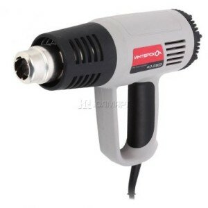
Accordingly, the electrical circuit of a building hair dryer is similar to the electrical circuit of an ordinary hair dryer.
An explanation will be given in the stated topic:
- electrical diagram of a building hair dryer;
- the principle of the construction hair dryer;
- possible reasons for the malfunction;
- elimination of these malfunctions.
Consider the electrical circuit in Fig. 1 of the building hair dryer:
One diagonal of the diode bridge is connected to an external source of alternating voltage 220V.
The other diagonal of the diode bridge is connected to the electric motor.
The electrical diagram consists of the following elements:
- toggle switch performing the control temperature mode - K1;
- a toggle switch that controls the speed of the blowing speed of the electric motor rotor - K2;
- toggle switch for disconnecting heating elements - K3;
- fan motor - M;
- capacitor - C;
- Heating elements - RTEN;
- diodes - VD1, VD2.
Through the diode bridge circuit of one diagonal of the bridge, the rectified current of two potentials +, - is supplied to the electric motor. When passing from the anode to the cathode, the current flows with a positive half-cycle of the sinusoidal voltage.
Two capacitors connected in parallel in an electric circuit serve as additional smoothing filters.
The blowing speed occurs due to the variability of the resistance in the electrical circuit, that is, when the speed toggle switch is switched to the highest resistance value, the rotation speed of the electric motor rotor decreases due to the voltage drop.
The number of heating elements of heaters in this scheme is four. The temperature regime of the construction hair dryer is carried out by the temperature control toggle switch.
The heating elements in the electric circuit have different resistance, - accordingly, the heating temperature when switching from one section of the electrical circuit to another - heating the heating elements will correspond to its resistance value.
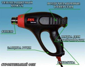
The general appearance of the construction hair dryer with its names of individual parts is shown in Fig. 2
The following electrical diagram of the building hair dryer in Fig. 3, is comparable to the electrical circuit in Fig. 1
There is no diode bridge in this wiring diagram. Blowing speed control and temperature control - occurs when switching from one section of the electrical circuit to another, namely:
- when switching to a section of an electrical circuit - consisting of a diode;
- when switching to a section of an electrical circuit that does not have a diode.
When a current flows in the anode-cathode junction of the VD1 diode, which has its own resistance, the heating element2 will heat up according to two resistance values:
- resistance at the transition anode - cathode diode VD1;
- resistance of heating element heating element 2.
When a current flows in the anode-cathode junction of the diode VD2, the voltage supplied to the electric motor and the heating element1 will take the lowest value.
Accordingly, the speed of rotation of the rotor of the electric motor and the heating temperature of the heating element for a given section of the electric circuit will correspond to the direct transition of the current of the diode VD2.Heating of the heating element heating element1 for a given section also depends on its internal resistance, that is, the resistance of the heating element is taken into account.
The main reasons for the malfunction of the construction hair dryer here can be called the malfunction of the electronic elements:
Most often, such a malfunction occurs with a sharp jump in an external source of alternating voltage. For example, the cause of a capacitor malfunction is caused by the fact that the capacitor plates are short-circuited when there is a voltage jump among themselves.
Of course, such a possibility of a malfunction as a rupture in the stator winding of an electric motor, winding burnout, is not excluded.
Minor malfunctions include such reasons as:
- oxidation of the temperature control toggle switch contacts;
- oxidation of the contacts of the toggle switch for controlling the blowing speed;
- oxidation of the contacts of the toggle switch for disconnecting the heating elements;
- a wire break in a network cable;
- defective plug lack of contact.
Diagnostics to identify the cause of the malfunction is carried out by the "Multimeter" device.
When replacing a capacitor, its capacity and voltage rating are taken into account.
When replacing a diode, the resistance of two values is taken into account, in the directions:
- from anode to cathode;
- from the cathode to the anode.
As we know, the value of resistance from anode to cathode will be significantly less than from cathode to anode.
With an electric motor, if it malfunctions, things are more complicated. With such a malfunction, it is easier to replace the electric motor than it is permissible to rewind the stator windings. But even such work is doable - who is directly involved in such repairs. In this case, the following is taken into account:
- the number of turns in the stator winding;
- section of copper wire.
Such a malfunction as burnout of the heating element is not excluded. Replacing the heating element is carried out taking into account its resistance value.
Consider the device of electric motors and how exactly it is necessary to diagnose electrical machines, as they are usually considered in the section on electrical engineering.
For an illustrative example, photographs of several types of such electrical machines are presented - related to collector motors. The device and principle of operation are admissible two collector electric motors:
- is no different. The difference in electric motors is only in the rotor speed and in the power of the electric motor. Therefore, we, as it were, will not focus our attention in the sense that explanations are given that are not related to the electric motor of the construction hair dryer.
The electric motor of the building hair dryer is asynchronous, collector, single-phase alternating current.
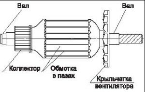
The rotor device does not require any explanation, since everything is shown in the photograph in Fig. 4 and a schematic representation of the electric motor rotor.
asynchronous collector motor single-phase alternating current
The electrical diagram of the collector motor in Fig. 5 is as follows:
In the circuit, we can notice that the collector motor can operate on both alternating and direct current - these are the laws of physics.
The two stator windings of the electric motor are connected in series. Two graphite brushes in contact - in electrical connection with the motor rotor collector.
The electrical circuit closes on the rotor windings, - accordingly, the rotor windings in the electrical circuit are connected in parallel through the brush-collector sliding contact.
diagnostics of stator windings of an electric motor
The photograph shows one of the methods for diagnosing the stator windings of an electric motor. In this way, the integrity or insulation breakdown of the stator windings is checked. That is, one probe of the device is connected to any of the removed ends of the stator windings, the other probe of the device is connected to the stator core.
In the event that the insulation of the stator winding is broken and the winding wiring shorts to the core, the device will indicate a zero resistance value in the short circuit mode. It follows from this that the stator winding is defective.
The device in the photograph indicates a one when diagnosing - this does not mean that this stator winding is suitable for operation.
It is also necessary to measure the resistance of the windings themselves. Diagnostics is carried out in the same way, - the probes of the device are connected to the removed ends of the wires of the stator windings. With the integrity of the windings, the display of the device will indicate the resistance value possessed by this or that winding. If one or another stator winding breaks, the device will show "one". If the stator winding wires are short-circuited with each other as a result of overheating of the electric motor or for other other reasons, the device will indicate the lowest zero resistance value or "short circuit mode".
How to check the resistance of the rotor winding with a device? - To do this, you need to connect two test leads of the device to two opposite sides of the collector, that is, you need to make the same connection that graphite brushes have in electrical connection with the collector. The diagnostic results are reduced to the same indications as when diagnosing the stator windings.
What is a collector in general? - The collector is a hollow cylinder consisting of small copper plates of a special alloy, isolated from each other and from the rotor shaft.
In the event that the damage to the collector plates is insignificant, the collector plates are cleaned with fine-grained emery paper. Again, this amount of work can be performed directly only by specialists who repair electric motors.
The electrical circuit in Fig. 7 consists of a battery and a light bulb, this circuit is comparable to that of a pocket flashlight. One end of the negative potential wire is connected to the stator core, the other end of the positive potential wire connects to one of the brought out ends of the stator windings. If the wires are connected the other way around, that is, "plus" to the stator core, "minus" to the withdrawn end of the stator winding, nothing changes from this.
In the presence of insulation breakdown, when the stator winding is closed with the core, the light in this electrical circuit will be on. Accordingly, if the light does not light up, then the stator winding is not closed with the stator core.
This method of diagnosing Fig. 7 is not complete. Accurate diagnostics is carried out only with an Ohmmeter device or a Multimeter device with a set resistance measurement range, for subsequent measurement of the resistance of the stator windings.
With the first task, (packing the flexible bus), the hairdryer did a great job, and I was even glad for a good purchase.
Then there were some other applications, and at one point it was noticed poor activation at increased power.
Quickly scattering it for parts, I made sure that the reason was in the switch (poor contact of the terminals did the trick).
Replacing the switch was not a problem, the problem was different. Before my eyes lay a "blank" that could be modernized to suit your needs.
- To be able to use the nozzles, temperature stabilization is required.
- For use in the installation of radio components, it is necessary to change the strength of the air flow.
- The hairdryer needs to cool to store it in the box. That is, it should be possible to turn off the heating of the spiral, without turning off the fan.
- In turn, the operation of one fan makes it possible to use a hair dryer to cool something, etc.
Actually, all of the above was introduced into the body of the cheapest hair dryer.
After turning on the power, the cooling mode is set:
- The heating of the coil is turned off.
- The fan runs at the first speed position.
- The lower limit of the airflow temperature setpoint has been set.
- The seven-segment display shows the air flow temperature.
- The "temperature" LED indicates, above or below the set point, the temperature of the air stream. If the temperature is higher than the set point, - green lights. If it is lower, it is red.
?
Air flow temperature setting.
The air flow temperature is set using the +/- buttons.
The minimum setting is 60 * C, the maximum is 630 * C.
The temperature changes in steps of 10 degrees.
The first short press on the temperature change buttons activates the temperature setpoint menu. Subsequent short pressing of the +/- buttons will change the temperature setpoint in increments of 10 degrees. If the button is held for more than one sec., The fast scrolling of the setpoint values is activated.
If the buttons are not pressed for more than one second, there is an automatic return to the air flow temperature display menu.
Changing the air flow rate.
The speed change is made using the +/- buttons, and has seven gradations. If the button is held down for more than one second, the accelerated "scrolling" is activated.
The speed indicator is a bar of LEDs.
The number of LEDs illuminated is proportional to the air flow rate.
Turning on the heating of the spiral.
Heating is switched on using the "heating" button.
Each press of the button will turn on or off the heating of the coil.
The glowing of the red LED indicates that the heating of the coil is on.
No glow, - heating is off.
The whole structure of the temperature and air flow rate regulator is assembled on two boards.
On first:
- Impulse power block. At the output it has + 16V for powering the fan motor, and two + 5V for powering the digital and analog parts of the regulator.
- Triac regulator, heating power of the hair dryer spiral. The method of skipping mains voltage periods is used, with a uniform distribution in time.
- Power switch, PWM fan motor speed controller. The hardware PWM of the microcontroller is used, with a frequency of 30 kHz.
?
On the second:
- Control and display unit. Includes, five control buttons, one three-digit seven-segment indicator of the measured air flow temperature, and its setpoint. Ten light-emitting diodes, seven of them, are a bar for indicating the air flow rate. Two, - temperature status indicator (above, below the set point). One, - indicator of turning on the heating of the spiral.
- Thermocouple amplifier, and MK.
?
Both boards are made using the method of laser-ironing technology. The first board with one-sided mounting of radio components, soldered to the terminals of the fan motor. The second, with two-sided mounting, is fastened with four self-tapping screws to the cover of the hair dryer. It is also the front panel of the control module.
The entire circuit is divided into seven functional units:
- Impulse power block.
- Coil heating control unit.
- Thermocouple amplifier block.
- Heating element and thermocouple.
- Fan motor control unit.
- Microcontroller.
- Input-output module.
?
The power supply is assembled on a TOP224 microcircuit, according to the original circuit
The power supply provides the circuit with three voltages:
16v - for powering the fan motor, maximum current 1A.
5vc - for powering the digital part of the circuit, current up to 0.5A.
5v - for powering the analog part of the circuit, current up to 0.05A.
Self-made assemblies, choke L1 and transformer TV1. The choke is wound on the "coil" frame, and must have an inductance of up to 10 μH, and also be able to pass the corresponding current of 1.5A.
The transformer is taken from a 20-watt energy saving machine. The central part of the core is 5x5mm. The number of turns of the primary winding was selected according to the "bald calculator". And in my case it was 72 turns. Was wound with a wire with a diameter of 0.23 mm. The secondary winding has 8 turns folded in four, the same wire is 0.23mm. The feedback winding has 7 turns, also folded into four wires. At maximum load, when the fan is powered from a full voltage of 16V, the transformer and the TOP224 microcircuit begin to heat up.However, due to the proportional increase in cooling (air flow), the temperature did not exceed 45 * C, at an ambient temperature of 32 * C. The measurements were carried out with an infrared thermometer DT8220, by the way, very convenient in this respect.
Of course, before making such transformers on your own, it is advisable to study the relevant literature. Because many points, assembly and winding of the transformer are not considered here.
Coil heating control unit.
The coil heating control circuit is based on the BTA41-600 triac.
Taken from the datasheet on MOC3063, and has no special features. An optocoupler with a line voltage zero detector provides "quiet load control". But since the load is of the order of two kilowatts, an incandescent lamp plugged into the same outlet will "show" the operation of the PI regulator (it will simply blink slightly).
The thermocouple amplifier circuit is based on an AD8551 operational amplifier.
This time, the wiring diagram is not taken from the datasheet, but it is pretty standard. The task of the amplifier is to enhance the emf of the thermocouple, therefore the OOS capacitance C10 is of great importance in filtering impulse noise. The low-pass filter at the output of U4 suppresses the 50 Hz component of the output signal. The gain is selected using the R24 resistor (roughly). A more accurate calculation is already done programmatically.
Heating element and thermocouple.
The design of the heating element has undergone a slight change. The coil of the fan motor power supply has been removed. And a thermocouple is inserted.
In the photo, the virgin state of the heater, the state after the alteration, unfortunately has not been immortalized. But there is nothing complicated there. The white wires that go to the motor power are removed in place with their spiral. The thermal fuse is connected using a crimp (not soldering) to the opposite end of the spiral with a resistance of 33 Ohm. The black wire of the additional spiral is simply bite off, and the end of the spiral remains in the ceramic. The red wire remains intact.
The thermocouple is passed through the vacant channel, where the thermal fuse used to be. The cold junction end of the thermocouple is connected to the board with screws. The cold seal is hidden under the red heat shrink tubing. The cold junction temperature is monitored by an internal MK thermometer. And in practice, it makes little difference, (1-2 * C).
Fan motor control unit.
The air flow is controlled by changing the speed of the fan motor. The turns, in turn, depend on the supply voltage. One of the simpler control methods is PWM (Pulse Width Modulation).
Hardware PWM is provided by MK. The selected frequency is 30 kHz, which makes it possible to do without a key driver. An intelligent transistor BTS113A is used as a key. And it can be replaced by a field-effect transistor with a "logic input".
The circuit uses MK PIC16F1823, this is a fourteen-lead stone. The clock frequency is 30 MHz, which makes it possible to process the incoming information quite quickly. Conclusions RA0, RA1, RA3, not used, left for development (if any).
In view of the small number of pins in the MK, and a large number of display and input elements (buttons), it was decided to use the 74HC164 shift register.
Transistors VT1-VT4 are soldered from some kind of board, and according to the designation on the case they are suitable for BC817 or BC337, in the SOT23 package.
LED1-LED10 LEDs, also in SMD version, but can be replaced by 3mm, without significant changes to the printed circuit board.
This text is available only for authorized users of the site.
This text is available only for authorized users of the site.
P.S. This article is presented not so much for repetition as for an incentive to search for new approaches and solutions when creating your own amateur designs.
The hair dryer has three levels of power and air flow rate adjustment, as well as smooth temperature control. Interskol hair dryers are made in China, the quality is consistent. There are many reviews and descriptions on the Internet, including on the manufacturer's website. My review is one more.
Hair dryer Interskol FE-2000. Serial number
The hair dryer is assembled in two modifications, which differ mainly in the circuits of the electronic boards.
The first option is on the board DB3011, switch board - DV3011-2. This board is assembled on a microcircuit (dual operational amplifier LM358) and a BTA16 triac or analogs - BT139, etc.
The second modification is a board DB230V, the circuit is assembled on an optocoupler P521 and a triac. The switch board is named DG-KG3.
First, let's look at the circuit of the hair dryer on the DB3011 board. Below is an exploded photo:
Electrical connection diagram:
Hair dryer Interskol FE-2000. DB3011 board. Connection diagram
In the diagram:
- C1 - 0.22 μF x 275V (for noise suppression)
- R1 - 27 ... 28 Ohm - low-resistance (powerful) heating element
- R2 - 180 ... 195 Ohm - high-resistance heating element (coil)
- F - thermal fuse (Lebao RVD-135 250V 10A TF = 135 ° C)
- M - motor, 18 VDC
- Switch - 4 positions, Defond DSE-2410
Diagram of the DB3011 board itself:
Hair dryer Interskol FE-2000. DB3011 board. Connection diagram and board diagram (option 1)
In this article I will outline my experience in the repair of a professional industrial hair dryer Interskol FE-2000... Sparks flew from it, smoke went out. It was not easy with the hair dryer circuit, what I found and what I drew myself, I post here.
The hair dryer has three levels of power and air flow rate adjustment, as well as smooth temperature control. Interskol hair dryers are made in China, the quality is consistent. There are many reviews and descriptions on the Internet, including on the manufacturer's website. My review is one more.
Hair dryer Interskol FE-2000. Serial number
The hair dryer is assembled in two modifications, which differ mainly in the circuits of the electronic boards.
The first option is on the board DB3011, switch board - DV3011-2. This board is assembled on a microcircuit (dual operational amplifier LM358) and a BTA16 triac or analogs - BT139, etc.
The second modification is a board DB230V, the circuit is assembled on an optocoupler P521 and a triac. The switch board is named DG-KG3.
First, let's look at the circuit of the hair dryer on the DB3011 board. Below is an exploded photo:
Electrical connection diagram:
Hair dryer Interskol FE-2000. DB3011 board. Connection diagram
- C1 - 0.22 μF x 275V (for noise suppression)
- R1 - 27 ... 28 Ohm - low-resistance (powerful) heating element
- R2 - 180 ... 195 Ohm - high-resistance heating element (coil)
- F - thermal fuse (Lebao RVD-135 250V 10A TF = 135 ° C)
- M - motor, 18 VDC
- Switch - 4 positions, Defond DSE-2410
| Video (click to play). |
Hair dryer Interskol FE-2000. DB3011 board. Connection diagram and board diagram (option 1)


