In detail: do-it-yourself cylinder head repair 2112 16 valves from a real master for the site my.housecope.com.
4.22. Details of the cylinder head: 1 - the head of the block; 2 - intake camshaft; 3 - stuffing box; 4 - an exhaust camshaft; 5 - camshaft bearing housing; 6, 8 - sealing rings; 7 - guide tube; 9 - block head cover; 10 - bracket for attaching the wiring harness; 11 - plugs; A - the distinctive belt of the intake camshaft
Head 1 (Fig. 4.22) of the cylinder block is common for four cylinders, cast from an aluminum alloy, with hip-shaped combustion chambers. The inlet and outlet channels are brought out to different sides of the block head. The valves are arranged in a V-shape in two rows: on the one hand the intake, on the other - the exhaust.
Sintered valve seats and brass valve guides are pressed into the head. The inner diameter of the guide bushings is (7 ± 0.015) mm, the outer diameter (for bushings supplied as spare parts) is 12.079-12.090 mm and 12.279-12.290 mm (the bushing is increased by 0.2 mm).
The valves are similar in design to those of the engine mod. 2110, but have smaller plates and rods. The inlet valve has a disc diameter of 29 mm, and the outlet valve has a diameter of 25.5 mm. The diameter of the inlet valve stem is (6.975 ± 0.007) mm, the diameter of the outlet valve is (6.965 ± 0.007) mm.
One spring is installed for each valve. The length of the spring in a free state is 38.19 mm, under a load of (240 ± 9.6) N [(24.5 ± 0.98) kgf] should be 32 mm, and under a load of (550 ± 27.5) N [( 56.1 ± 2.8) kgf] - 24 mm.
The valves are actuated by camshaft cams through cylindrical hydraulic pushers located in the guide holes of the cylinder head along the axis of the valve holes. Hydraulic pushers automatically eliminate valve clearance, so there is no need to check and adjust valve clearance when servicing a vehicle.
| Video (click to play). |
4.23. Power unit suspension with engine mod. 2112: 1 - bracket on the right side member of the body; 2 - lower pillow limiter; 3 - cushion of the right support; 4 - the upper limiter of the pillow; 5 - cushion fastening nut; 6 - distance washer; 7 - support fastening nut; 8 - right support bracket; 9 - rear support bar; 10 - rear support bracket; 11 - cushion of the left support; 12 - nut with washer; 13 - left support bracket; 14 - front support bracket; 15 - bar of the front support
Oil for the operation of hydraulic pushers is supplied from the lubrication system through a vertical channel in the cylinder block to the channel in the cylinder head about the 5th fastening bolt (see Fig. 4.23), and then through the upper channels made on the lower plane of the bearing housing. Through the same channels, oil is supplied to lubricate the camshaft journals. A check ball valve is located in the vertical channel of the cylinder head, which prevents the oil from draining from the upper channels after the engine is stopped.
Two camshafts are used to drive the valves: intake and exhaust. The shafts are cast from cast iron and equipped with five bearing journals, which rotate in seats made in the cylinder head and in one common camshaft bearing housing. To increase wear resistance, the working surfaces of the cams and the journal for the oil seal are bleached. To distinguish the intake camshaft from the exhaust camshaft, a distinctive band A is provided on the intake shaft near the first support.
The shafts are held against axial movements by thrust collars located on both sides of the front support. The front ends of the camshafts are sealed with self-tightening rubber seals.The rear holes located along the axis of the shafts in the cylinder head and bearing housing are closed with rubberized cap plugs.
Checking the technical condition and repairing the cylinder head are similar to those described for the engine mod. 2110.
You will need: a device for compression of valve springs, a tool for pressing out and a mandrel for pressing in valve stem seals, a socket wrench "10", a hexagon "10", a screwdriver, tweezers.
1. Remove the cylinder head from the engine (see "Removing the cylinder head on the vehicle").
2. Unscrew the coolant temperature gauge sensor from the rear end of the block head.
3. Unscrew the oil pressure drop warning lamp sensor from the camshaft bearing housing.
4. Remove the two mounting bolts and remove the fuel pipe bracket.
5. Remove the spark plug guide pipes from the cylinder head and camshaft bearing housing bores.
6. Remove the sixteen camshaft bearing housing bolts.
8. Remove the plugs from the rear end of the block head.
9. Remove the camshafts from the cylinder head supports and remove the oil seals from their front ends.
10. Remove the hydraulic valve pushers from the holes in the cylinder head.
11. Remove the crackers from the spring plates by compressing the valve springs with a tool.
12. Remove the springs with pockets.
13. Turn the cylinder head over and remove the valves from its bottom side.
14. Remove the valve stem seals from the guide bushings.
15. . and spring washers.
16. Before reassembling, clean the cylinder head and bearing housings from old sealant residues, dirt and oil.
17. Install the spring support washers.
18. Lubricate the valves, hydraulic tappet holes, valve guide holes and new valve stem seals with engine oil (old seals cannot be used).
19. Press the caps onto the guide bushings with a mandrel.
20. Insert the valves into the guide bushings, install the springs and spring plates.
21. Compressing the springs with the device, install the valve cotters.
22. Insert hydraulic valve pushers into the holes of the cylinder head.
23. Lubricate the bearing journals and camshaft cams with engine oil and place them in the cylinder head supports.
24. On the surface of the cylinder head mating with the camshaft bearing housing, apply Loctite-574 sealant in the form of a 2 mm diameter bundle, as shown in the photo.
25. Install the bearing housing and tighten the bolts of its fastening evenly crosswise, starting from the middle supports.
26. Press in new camshaft oil seals with a mandrel (you can use a head from a set of tools or a piece of pipe of a suitable diameter as a mandrel), having previously lubricated them with engine oil.
27. Press in the plugs on the other side of the cylinder head.
28. Place the O-rings on the spark plug guide pipes and lubricate them with engine oil.
29. Install the guide tubes into the holes in the cylinder head and the camshaft bearing housings.
30. Screw the coolant temperature gauge sensor into the cylinder head.
31. Screw the oil pressure drop warning lamp sensor into the camshaft bearing housing.
32. Install the fuel pipes retaining bracket on the cylinder head.
Reference manual for the maintenance of cars VAZ, LADA 110.
Ignition adjustment 2110. Compression of the engine VAZ 2112, immobilizer for VAZ 2111. Valve cover VAZ 2112, cylinder block gasket VAZ video. The cost of a generator for a vaz. replacement of fuses VAZ 2112, the design of the oil receiver VAZ 2112. Factory recommended oil in the box VAZ 2112. Replacement of the water pump (pump) VAZ 2112.Replacing the valve stem seals VAZ 2110.
Cars of the VAZ-2112 family were produced with one of two 16-valve engines - 21124 and 21120. The working volume of these engines is different, and only one part called "cylinder head" is used - it is designated by the numbers 2112-1003011. It is rumored that the cylinder head from the 21120 engine does not fit the 24th engine, but a reverse replacement is possible. However, there is only one SKU in the parts catalog, and it fits two motors at once. Further, it is considered what actions to repair the VAZ-2112 cylinder head you can perform yourself. We will only talk about 16-valve valves.
An example of dismantling is shown in the video. We look.
First of all, to get to the cylinder head, you need to remove the cylinder head cover. For different 16-valve valves, this operation is different, and the article numbers for the cover also look different: 2112-1003260 (-10) and 21124-1003260.
Cover from the internal combustion engine VAZ-21124 (1.6 l)
The timing belt will also need to be removed - there are no differences in different engines.
Consider how you can detach the exhaust manifold from the cylinder head. On engine 21120:
-
Remove the exhaust pipe of the muffler: unscrew two nuts 1 (key "13"), remove the clamping bar, unscrew six nuts 2 (key "14") and dismantle, not forgetting to turn off the oxygen sensor. The photo shows three nuts out of six.
Everything important is under the screen
Now we will talk about the 21124 engine:
- We turn off both oxygen sensors. We unscrew the three nuts securing the protective screen (key "10") and disassemble the bracket by unscrewing the four nuts with the key "13".
How to disassemble the mounting bracket
Operation with additional silencer
Here we considered that the VUT hose was disconnected from the intake module. In the end, the candles are unscrewed on any of the engines (pipe wrench "16").
The tightening torques for the fastening screws are given in a different text. In general, on VAZ-2112 hatchbacks, cylinder head repairs begin by replacing the "elongated" screws with new ones. The length must be 95 mm or less.
The procedure for loosening (left) and tightening the fastening screws
Taking a wide steel ruler, they check:
Measurements are taken along each of the diagonals. Use a set of probes.
To remove any valve, you will need to remove the camshaft. All screws on the bearing housing must be unscrewed evenly, and tightened with a force of 10 N * m. The hydraulic compensator can be removed with a magnet, and then the valve is dried by compressing the spring with a puller (see photo).
Carbon deposits may be present in the valve passages. It is cleaned off:
- Flat screwdriver;
- Sanding felt.
Lapping is carried out as follows: a rubber pipe is put on the valve, a paste with diamond chips is applied (one drop), then the valve is pressed into the channel and scrolled. It will be possible to change the valve stem seals (2112-1007026). You can't do without a special puller.
On any car, including the VAZ-2112, cylinder head repair is reduced to cleaning and checking, as well as correcting geometry defects. In the latter case, we are talking about milling. The presence of cracks and chips is a reason for replacement, not for repair.
The burned-out valve can be seen immediately.
One valve in cylinder 2 burned out
Carbon deposits were found in each valve channel.
Carbon deposits in the cylinder head channels
Repair: cleaning all channels, replacing the valve with lapping.
Direct repair of the VAZ 2112 cylinder head will require several operations in which some special equipment is needed. Of course, at home there is no such possibility, and motorists simply replace worn out parts. Next, we will consider the process of repairing the head of the block, as well as some of the nuances associated with this work.
Before proceeding directly to the cylinder head repair process, it is worth noting that the head must be completely disassembled and all the necessary spare parts purchased. Consider the process of a complete overhaul of the cylinder head.
The process of washing car spare parts with hot kerosene
In order to wash the head, it must be completely disassembled, that is, all parts that can be easily removed are dismantled. A full wash requires 12 liters of hot kerosene. In car services, this is done using a spray that delivers fluid under pressure. So, all the dirt and remnants of metal shavings are washed off. Washing is carried out until the cylinder head is completely clean.
Cylinder head crimping process
Crimping is a process by which the integrity of a part is checked. Crimping can be done in two ways, which are similar in principle. The first is to close all the cracks and fill the part with water. There is, somewhere water comes through or flows, then the integrity is broken and repairs are needed. The second method is to close all the cracks and the head is immersed in an aqueous solution. It will immediately be seen where the depressurization of the part takes place. If the integrity of the head is damaged, then it is necessary to restore it.
The valve seats must be removed before continuing with the rest of the overhaul. In the best case, they will easily knock out of the seat, and if not, then you will have to use Russian ingenuity.
The valve is welded to the seat and knocked out of the seat
So what if the valve seats aren't knocked out? The solution is simple. It is necessary to weld a tube to them so that the working end passes through the channel of the guide sleeve and knocks out until the saddle comes off the landing mount. Of course, cracks can form on the seat ring of the saddle or a piece break off. After completing the procedure, it is necessary to inspect the place and, if necessary, weld with argon welding.
Often, repairing the cylinder head is not complete without checking the plane. This can be done by contacting a car service that has a test stand, or by asking a neighbor in the garage for a special ruler for measuring the plane of the cylinder head.
Measurement of the cylinder head plane for deformation using a metal ruler and a probe
Important! It is recommended to give such block heads to a car service with the proper equipment, since only there they will be able to measure the plane and grind it to the desired size.
So, if there is a deformation on the block head or the plane has a deflection, then it must be sanded. This operation is done on a special surface grinding machine. Usually, the auto repairman is advised not to remove more than 10 mm of thickness. Consider the possible options for grinding the cylinder head by dimension:
- Repair 1 - 1-2.5 mm;
- Repair 2 - 2.5-5 mm;
- Repair 3 - 5-7.5 mm;
- Repair 4 - 10 mm - the maximum allowable value for grinding GBU VAZ 2112.
Cylinder head surface grinding process
Note! If you remove the thickness of the plane more than 10 mm, then this can lead to incorrect operation of the timing mechanism, loss of power and an increase in fuel consumption.
Argon welding is welding work that is carried out on aluminum. For this, a special gas is used - argon. So, to eliminate cracks and weld defects in the seats of the valve seats, it is required to weld them, and then carry out milling work on special equipment.
The process of repairing cracks in the cylinder head using argon welding
After the welding and milling work has been carried out, it is necessary to bring the surface to readiness. For this, the cylinder head is placed on a special stand, where the surface is polished using a special paste produced by ABRO or its analogues. This is necessary so that the surface does not have roughness. When this procedure is completed, it is necessary to once again wash the part from metal chips and residues of working material.
It is best to assemble the cylinder head at a special stand.
When the block head is processed and washed, you can proceed directly to its assembly. But, before that you need to carry out preparatory work. Let's consider all the stages of the assembly sequentially:
- The cylinder head housing is installed in a special heating furnace.
- In the meantime, measurements of the valve seat to the seat are taken, the guide bushings are unfolded.
- When the cylinder head is hot, it is taken out of the oven. On hot, the valve seats are installed.
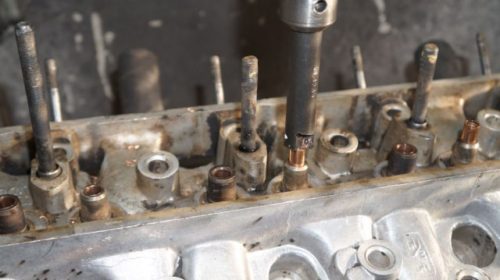


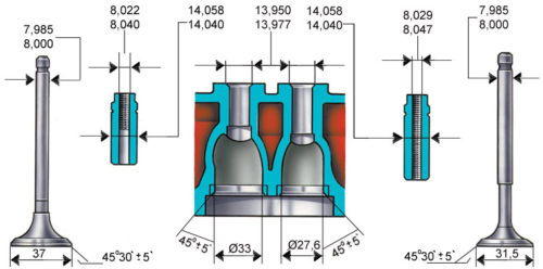


On a special stand, the valve chamfer is processed
Valve seat shrinkage process steps
Valve Lapping Process
Thus, a major overhaul of the cylinder head of a 16-valve VAZ 2112 engine is being carried out. This process will take 1-2 days at a car service, but a motorist can spend much more time in his garage, since the lack of a tool will affect. So, it is recommended to repair the cylinder head at car services, where everything will be done much faster and better. Of course, this will hit the pocket, since a high-quality and overhaul of this part will cost on average about 7,000-10,000 rubles. together with spare parts.
The cylinder head of the VAZ 2112 16 valves is one of the most important parts of the power unit. The normal operation of the engine depends on its condition. Therefore, during the entire operation of the machine, it is necessary to constantly diagnose it and replace consumables. The article describes the process of removing and installing the cylinder head of 16 valves, what kind of device it is and why repair is needed. In the attached video, you can clearly see the entire process of dismantling the head.
The cylinder head is an important and complex part of the engine design. It is a cover that covers and protects the cylinder block: combustion chambers, channels of the lubrication system, the main parts of the timing belt, etc. It is made of alloyed cast iron or aluminum alloy.
The head on the VAZ 2112 has the following structure and, accordingly, functions:
- a cover designed to protect the cylinder block from external influences;
- in the place where the cover is attached to the cylinder block there is a rubber gasket that serves for sealing;
- in the front of the block, there is a camshaft drive and a chain tensioner;
- combustion chambers;
- threaded holes for injectors and spark plugs;
- the head body also has holes in which the inlet and outlet manifolds are attached.
At the top of the head is where the bushings, valve springs, thrust washers and camshafts are located. A place has been set aside for the timing.
Timely diagnostics of the cylinder head on the VAZ 2112 is necessary for the normal operation of the engine, especially with 16 valves. When operating a car, overheating of the device should be excluded, as the head can move. To adjust the valves and replace the valve stem seals, there is no need to dismantle the cylinder head. Removing the head is necessary for major repairs:
- when the guide bushings are changed;
- if you need lapping and replacement of the valve guides;
- removing carbon deposits from parts;
- replacement of the gasket;
- replacing the camshaft and its beds;
- machining of adjoining planes.
During complex repairs, small parts are changed and, if necessary, lapping, removal, revision and adjustment of the valves are carried out.
The stages of removing and repairing the cylinder head on a VAZ212 16 valves are given below, they can be clearly seen in the video.
- Removal begins with disconnecting the minus terminal from the battery.
- Then the connectors of the sensors, the supply hoses, are sequentially disconnected.
- Next, we disconnect the throttle valve drive, the exhaust pipe of the muffler,
- Remove the fuel pipe bracket, as well as the receiver and throttle assembly.
- Next, we dismantle the cylinder head cover.
- After removing the engine rear support bracket, remove the camshaft toothed pulley. Then dismantle the rear timing belt cover.
- Having disconnected all the mounted sensors, equipment and removed the holders, using a hexagon, unscrew 10 bolts in sequence and remove them together with washers.
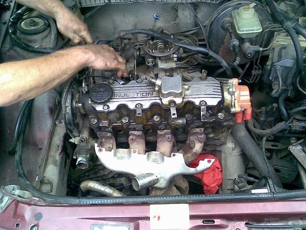
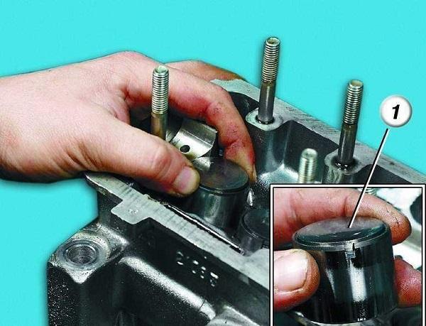
This completes the do-it-yourself check of the technical condition, revision and repair of the cylinder head on the VAZ 2112.
Video "Assembly and disassembly of the cylinder head on the VAZ 2112"
This video shows the process of dismantling and installing the VAZ 2112 cylinder head required for repair.
For a long time I could not understand what the reason was - the antifreeze was leaving somewhere. Everything that you can see. Nothing flows anywhere. I noticed thick white smoke from the exhaust. Condensation was dripping from the exhaust. I tried it on my tongue, the verdict was - antifreeze.
I drove into the garage and unscrewed the candles, and then everything became clear to me - the candle in the first cylinder was black. With lumps of soot. The plug is in the cylinder, the piston is wet. There were reflections of moisture.
Frightened than the current could. On the forums they wrote Crack in the cylinder head - a crack in the block. It was scary to guess. In general, it was decided to disassemble it myself.
I began to disassemble from the Gas Distribution Mechanism
We put the car at 1 speed and rip off the bolts from the camshaft pulleys.
Dismantle the alternator belt and alternator belt pulley.
HOW TO REMOVE THE ALTERNATOR PULLEY? Yes, this method is not very good for a starter, but that's how I use it. You can fix, clamp, etc. And you can take a knob with a head, insert the key (knob) into the generator pulley bolt, support it in the lever and ask the assistant to turn the starter for 1 second. (If you are not sure of the assistant, remove the chip from the ignition block) The bolt comes off, and we are happy.
We drain the antifreeze (antifreeze) from the engine. We look at the oil dipstick. Do you see him? Don't look at it for a long time, just shoot.
So, and next to the well where the probe is inserted, we unscrew the plug in the cylinder block. Antifreeze (antifreeze) will rush into the radiator with a confident stream. Get ready for this.
If anyone does not know, we dismantle the timing belt tensioner, remove the belt. Tryndets labels.
We remove the pulleys. Not filmed? We swing the pulley left - right and pull towards ourselves.
ATTENTION: key. When removing the pulley, catch the key. This is such a little iron muck that loves to get lost or fall out somewhere.
We remove the explosive wires (number who is not sure what will put it right)
Remove the ignition block.
We disconnect the corrugation from the receiver, the breather, remove the DMRV chip.
We remove all the hoses from the receiver (we fix the cooling hoses at the highest point, you can put them behind the spacer) Disconnect the IAC and DZ position sensor chips, remove the gas cable. We also remove the hoses from the receiver (Vacuum cleaner, fuel regulator, etc.) Unscrew the receiver from the pillows. We twist 4 clamps from the inlet pipes. We remove the receiver.
Unscrew the thermostat completely.
Above the thermostat, the 2 masses are unforgettable.
We remove the exhaust (it will most likely be possible to unscrew it only with the pants.
We unscrew the gas line (make a mark on one of the hoses (you can scratch the fitting with a knife) There will be rings (rubber) for replacement.
I would like to draw your attention. Before unscrewing the cover. BUY A NEW HEAD. The tightening can be very strong. WILL NEED AN EXTENSION CORD.
It will not be entirely correct to rip off and immediately unscrew one bolt at a time.
At first, we just rip off all the bolts.
Then we loosen all the bolts.
Then you can unscrew it in any order.
This way you will never deform the part.
Everyone knows that it is not worth tightening the cylinder head in any order.
Correct twisting according to the scheme 1.2.3.4.5.6.7.8.9.10
IT UNLINKS IN REVERSE ORDER.
That is 10.9.8.7.6.5.4.3.2.1
WHY? I will explain when we will collect.
The bolts are not loosened in order. In order, they break down. ripped off 10.9.8.7.6.5.4.3.2.1? Relaxed? Unscrew further at least.
Did you unscrew everything? We take out the head. The rest can be done at home, or if it's warm in a freer space.
Now it remains to find the cause of the breakdown
To begin with, I look at the Cylinder Block. Here and the gasket lies.
And then everything became clear - the gasket burned out.
In the meantime, we have not moved away from the Block of Cylinders, hereinafter referred to as the BC, we are looking at its condition.
Third cylinder (ACCOUNTED) 2
Third cylinder (COUNTED) 3
Honestly, the state is good. Not any cloudiness on the mirror, scoring and other troubles including cracks. The only thing is there are minor scratches (in the form of a wave) Everything is visible in the pictures
ATTENTION: DO NOT CLEAN THE PISTON ON THE NAGAR. Unless of course there is a crust of 50 layers. Carbon deposits are a kind of protection against overheating.
In general, everything is fine in the business center for a 2001 car. Or rather, perfect.
Now it's time to go to the cylinder head.
Namely, look at its condition and valves.
It looks like everything is fine and if it were not for the gasket, then everything would still work.
The photo shows the combustion chamber of 1 cylinder. As you can see, soot just falls off. Thickness is about 1 mm. Looking under the valve, we see that everything is covered with soot.
Not one valve has burnt out. Everything is fine. I cleaned the valve with carbon deposits.
And he took the cylinder head home to disassemble and wash. For convenience, we need to wash the head of the cylinder head. To do this, we take a bath of hot water, throw in 2 bars of soap, 1 pack of powder, liquid for cleaning the stove (acid and alkali), take an iron crack and drive it to shine until it shines. Now we carry the head to the scrap metal collection point. Well, or at least half of the spare parts from it.
In order to wash it, you need to disassemble it. Here is such a nuisance.
With the head removed, we spread the camshaft bed (correct if not said so). We take out the camshafts with them. Honestly, I do not know. can they be confused or not. But just in case, I put on the intake camshaft its gear with phases for the sensor (skirt).
Immediately remove the timing sensor from the cylinder head. If you didn't immediately notice it, then most likely you have already torn the wire from it. But just in case. it is located near the exhaust pulley.
We take out the candle wells, they should have sealing rings (rubber), we throw them out, we will have to buy new ones., Why? because these rings can pretty much ruin the mood. Especially when everything flows into the wells.
Bed with camshafts. (A)
Hydraulic compensators
Before removing them, we check for operability (depression). After we removed the camshafts, simply press on each wetsuit in turn with your finger. If some one is forced through, then he or already knocks. Or wait.
Next, we remove the hydrocompinastors. How to do it? We take a magnet, preferably more powerful, just magnetize the wetsuit and pull it towards ourselves with left-right movements.
I would not pull them out with tweezers, round-nose pliers. In any case, it will be more whole with magnets. Nothing is written anywhere. But I put them in order and put them in the same order. (Your business).
We dry the valves. I preferred to do this with the most useless device. And from the top, by the way, a magnet for hydrics (adapted).
This decanter bent, broke off, and in some places did not fit. To be honest, I've seen a lot of such devices. But if you do not want to suffer, do not buy this type.
For desiccation, we need a desiccant and tweezers. And also some kind of rag or piece of wood.A rag or piece of wood (you can use an elastic band). I took 2 gloves folded into each other and put the head on them (so that the gloves were in the combustion chamber.) Why do that? So that when you clamp the spring with the drying agent, the valve does not go down together with the spring and the plate. An object lying in the combustion chamber will prevent the valve from moving with the spring and the disc. If someone has other ideas, write, I want to say right away that I did not work on a workbench and you cannot hold the valve here with your hands.
Russukhariev. We fix the desiccant next to the spring.
Press the spring with a desiccant, keep it in a pressed state. With the other hand, at this moment, we take out 2 crackers. Pulled out? - Now you can pull out the 2 spring and valve pockets. All this should be folded to the hydraulic compensator of the valve on which it all stood (together with the valve) if the valves are to be replaced, then they can be immediately thrown into a separate box.
Yeah. I see you removed 1 valve? I will make you happy to shoot 15 more. You have an exciting pastime ahead. (if you do it for the first time)
Valves, how to understand that they need to be changed? There should be no burnout, cracks or grooves on the valves. I changed my 8 intake valves. Why?
Do you see the black dots? This is carbon deposits in the grooves. If you pour water and check endlessly, then there will be no leaks. But when you increase the compression, they will still skip a little. And then they burn out. No need to grind, cut, mill it all.
Intake valves. They should also be brought in order. Through an ordinary piece of paper, we clamp the valve by the leg into the drill chuck. We turn on the drill and work with a sandpaper.
Attention. when working with a leg (skin), be careful. Do not machine the surface on which the guide walks.
Injectors and intake manifold, remove the intake manifold (gasket for replacement). We unscrew the nozzles and remove them. How? swing the entire ramp up and down and pull it towards you. That's all there are no nozzles. But we will talk about them separately. In the article, cleaning the nozzles.
Cleaning the cylinder head
OK it's all over Now. Now you can wash the cylinder head. The easiest way that I know.
We take the Profoam 1000 liquid
We just spray the entire cylinder head and rinse it after 5 minutes.
And so 3 times. After the second time, you can shuffle with a sponge brush (not iron)
We do the same with the bed and the valve cover (after removing the mesh)
Have you washed and dried everything? Yeah. Now it is advisable to change the valve seals so that later questions do not arise.
Valve oil seals.
Many say they are half defective, others say that they are all defective and it is better to leave the factory ones. In fact, everything is simpler. It's just that half of these people put them wrong. There are springs on the oil seals. So, when installed, they tend to fly off.
We remove the oil seals with a special puller.
Have you removed the oil seals? Wait to install. We take the valve and insert it into place. We raise it a little and try to wobble it. Staggering? This is already bad. In general, there should be a backlash. But it is very minimal. It is so that the valve sits correctly in the closed position. Again, if there is a good backlash, you have broken guide bushings. I was lucky.)
There are many ways to replace the rails, the best of all is the (puller) you can build yourself. Watch the video THEORY OF ICE.
Is there no backlash or is it very insignificant? We put everything in place. In the video, I roughly explained how this is done. Lubricate with oil and hammer with a puller. But you can also use some kind of mandrel.
Cleaning channels from carbon deposits. Most likely you could not help but how to clean the carbon deposits from the cylinder head channels.
The drill will help us again. And metal discs.
For valve channels
I did not find less in the store. I had to grind the disc a little on the materials at hand. First, we clean the inlet channels (large) then, when the brush is more or less wasted, we clean the outlet (small)
ATTENTION. Do not damage the phases on the saddles. We insert a drill with a brush, start it outside the phase and only then turn it on and go deeper with a brush. And so all the valve channels.
Then we clean the main channels. To begin with (for convenience), it is natural to enter as it is larger. Then release, when we have already bored out the brush.
Now for the assembly. I won't say much. Let's just say - I will draw your attention to the most important points.
We collect the cylinder head
We sugar everything in place. All 16 valves.
We insert hydrocompensations. It is advisable to buy new ones or service old ones. It will be more reliable. By the way, dip them completely in oil before inserting them. Naturally not sunflower.
Insert the camshafts. Do not forget that they, each, have their own place. Previously, all necks, cams, lubricated with oil.
We insert candle wells (having bought new rings) And it is advisable to treat them with a sealant, having previously degreased.
We twist the camshaft bed. To begin with, coat with good. with a sealant (having previously degreased so as not to bother where, what to smear here is the diagram:
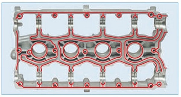
For those who did not understand, the red stripes are the sealant.
There are all sorts of schemes. This one turned out to be closer to me.
Do not forget the oil seals, with sealant.
Collected? Turn the camshafts. Are they cranking?
Check if everything is in place.
Now to the garage.
We clean the BC from any dirt (surface)
We put the gasket.
We attract everything according to the scheme (in the previous parts I talked about this)
We smear the valve cover in a circle. And near the bolt holes.
And then, we collect everything in reverse order
This revision will be useful in almost the entire line of VAZ injection engines, regardless of
The procedure is carried out when replacing the head gasket, repairing the valve mechanism and the head itself, as well as when completely disassembling the VAZ 2110 engine.
Disconnect the negative wire from the battery, drain the coolant.
Disconnect the throttle actuator cable, front pipe, “ground” wires from the left end of the head, connectors of the coolant temperature and oil pressure sensors, hoses of the outlet pipe of the cooling system.
We remove the receiver with the VAZ 2110 throttle assembly, the intake manifold, the fuel rail with the VAZ 2112 injectors and pipes, the cylinder head cover, the rear support bracket of the power unit, the camshaft toothed pulleys and the rear timing belt cover of the VAZ 2112.
You can dismantle the head without removing the intake and exhaust manifolds. In the shown variant of disassembly, the collectors have been removed for clarity. For all of the above dismantling operations, see the respective sections.
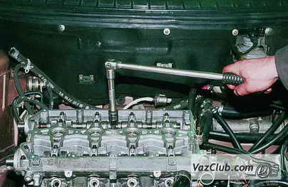
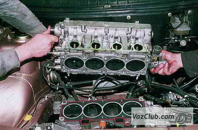
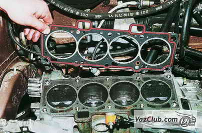
We carry out further disassembly of the head on a workbench.
We dismantle the camshaft bearing housing, remove the camshafts and take out the hydraulic pushers (see Replacing the hydraulic pushers of the VAZ-2112 engine valves).
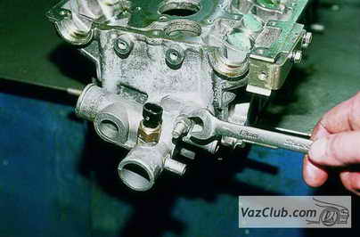
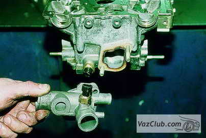
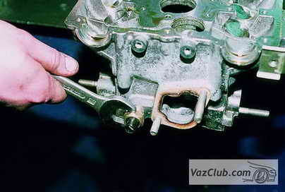
We dry out the valves, remove the springs with the plates (see Replacing the valve stem seals of the VAZ-2112 engine).
To stop the valves of the VAZ 2112, when the springs are compressed, we put a wooden block under their plates (from the bottom of the head).
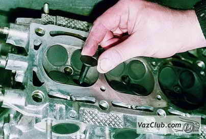
- - Remove the valve stem seals from the guide bushings and the spring support washers.
- - We assemble and install the cylinder head in reverse order.
- - Before installation, we clean the surfaces of the cylinder block and head 2112 from the remnants of the old gasket, dirt and oil.
- - Lubricate the valve stems of the VAZ 2111, the holes for the guide bushings, the holes for the hydraulic pushers and new valve stem seals with engine oil.
- - Remove oil and coolant from the threaded mounting holes of the cylinder block.
- - A new gasket and a cylinder head are installed on the block along two centering sleeves.
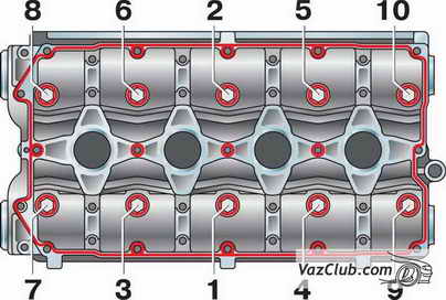
- - first reception - tightening 20 N • m (2 kgf.m)
- - second move - turn by 90 °
- - third technique - turn by 90 °
| Video (click to play). |
The head mounting bolts may only be reused if they are extended to a length of no more than 95 mm. If it is larger, replace the bolt with a new one.


