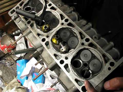
In detail: do-it-yourself repair of the cylinder head of a VAZ 2101 from a real master for the site my.housecope.com.
Since any repair begins with the removal of the part being repaired, we will briefly describe it. In order not to forget, and not to be surprised when disassembling, it is necessary to drain the coolant from the engine before starting the repair. To remove the cylinder head, you first need to remove the air filter, carburetor, having previously disconnected all wires and hoses from it.
After all this has been done, remove the cylinder head cover, align the marks on the crankshaft pulley with the mark on the camshaft drive cover and the mark on the sprocket or pulley (in the figure below, the asterisk) of the camshaft with the mark on its body.
Installing the crankshaft mark
Installing the camshaft mark
Then you should loosen the chain tensioner, unbend the camshaft sprocket bolt lock washer, unscrew the bolt (preferably with a jerk), carefully remove the sprocket from the camshaft and tie it with wire or something else to the chain. Now you can unscrew the camshaft nuts and remove it together with the housing. The next step is to remove the rockers, for this they must be pulled off the adjusting bolts and removed from the springs. Before removing the rockers, you need to mark with a marker or notches, so that each one sits in its place during assembly, then the running-in with the camshaft journals and the heads of the adjusting bolts will not be disturbed. Now you need to disconnect the wires from the spark plugs, from the coolant temperature sensor, disconnect the hoses from the cylinder head, unscrew the nuts securing the front pipe to the exhaust manifold and remove it. Next, unscrew the bolts with which the head is attached to the block. The cylinder head can now be removed for repair.
| Video (click to play). |
After removing the cylinder head, for the convenience of further work, its surface must be washed from all kinds of dirt and carbon deposits.
Repair of the VAZ cylinder head
begins with drying out the valves. For this, the tool shown in the figure below can be used.
Valve Dryer
It is advisable to put the valves in their places or mark them so that in case of slight wear you can put everything in place. Now you should carefully inspect the cylinder head for cracks, pits, potholes, corrosion, assess the wear of the seats and guides, the latter usually have to be changed after about 150-200 thousand kilometers. If, as a result of the inspection, no defects were found that could interfere with the repair, then you can continue.
So, if the guide bushings are worn out, then we proceed to replace them, they can be removed using a special device, the drawing of which is shown below.
Mandrel for knocking out the guide bushings
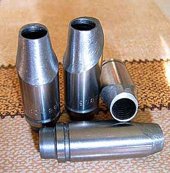
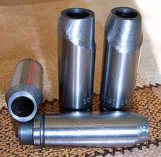
It is advisable, when pressing out the bushings, to immediately measure their outer diameter with a micrometer and write down, so that when buying new ones, go to a car shop with the same measuring tool and pick up a diameter of 0.05-0.07 more than relatives.
After the guides are purchased, we start pressing them in, for this we need: an electric stove, a mandrel for pressing the guide bushings, shown in the figure below, a hammer, machine oil.
Mandrel for pressing the guide bushings
We put the head of the block on some kind of stand along the edges, tuck the tile under the place where we will work, heat it up to 100C, while heating is on, grease the bushings with oil (or even better, put them in the freezer before that), remove from the stands and drive in there new guides. If these requirements are met, the bushings will go “like home” and you will not spoil anything. After replacing all eight, it is necessary to let the head cool down and then expand the inner diameter under the valves so that they do not dangle, but move freely, do not jam or jam, otherwise the entire head repair may go down the drain. I want to warn against a mistake that many make when working with a sweep: with this tool they work only in one direction with a passage to the end. In no case try to unfold the guide from both sides, this will not lead to anything good!
Now you can start the most painful work, the good performance of which largely determines the tightness of the valve to the seat and the entire cylinder head repair - countersinking. Usually they work with this tool in the following sequence: first, they pass the output cutter (the one on which 60 degrees is written) until the metal layer begins to be removed in a circle, then they take 120 degrees and cut it off until a clear round edge appears ... The last one, the one that is 90 degrees, all that remains is to make a working chamfer, the thickness of which should be 1.5-2 mm, it is advisable to make about 1.5, because when the valves are lapped in, it will increase slightly. A well countersunk saddle should look something like the illustration.
Repair of the VAZ cylinder head - View of a properly shaken saddle
Lapping the valves and checking the tightness of the cylinder head
Now it remains to grind the valves so that they fit as tightly as possible to the seats. This is done as follows: go to a car store, buy a special lapping paste (it is quite inexpensive), smear the valve on it, insert it into the head. Further, there are 2 ways of how to rotate it, while pressing it against the saddle: one is "old-fashioned", the other is more modern.
Let's start with the grandfather's. Find a piece of hose of such a diameter that it fits snugly on the valve, squeeze it between your palms and begin to rotate it in one direction or the other. A more modern device for holding the valve is shown in the figure below, it is not difficult to make it.
Tool for grinding cylinder head valves
An external indicator that the valve has rubbed in is the matte surface of the seat and valve at the point of contact, and it should be in a circle, not interrupted. After repair, the tightness of the cylinder head can be checked by pouring a little kerosene or gasoline into the intake and exhaust manifolds. With a well-performed work on the repair of the cylinder head, leaks and dampness from under the valves of the cylinder head are not observed for 5-7 minutes.
Finally, I can only remind you, do not forget to put the valve stem seals. And yet, do not forget to rinse and clean all the parts after repairs immediately before assembling the head, then the motor of your VAZ will last for more than one hundred thousand kilometers.
It's no secret that a well-repaired cylinder head is a guarantee of stable, trouble-free engine operation with maximum power output and normal fuel consumption, therefore repair of the VAZ cylinder head should be done with special attention, since any oversight can lead to damage to almost all parts of the engine and new expensive repairs. This article will describe in detail the repair of the VAZ cylinder head with your own hands, tips are given that are not in the books.
Since any repair begins with the removal of the part being repaired, we will briefly describe it. In order not to forget, and not to be surprised when disassembling, it is necessary to drain the coolant from the engine before starting the repair. To remove the cylinder head, you first need to remove the air filter, carburetor, having previously disconnected all wires and hoses from it.
After all this has been done, remove the cylinder head cover, align the marks on the crankshaft pulley with the mark on the camshaft drive cover and the mark on the sprocket or pulley (in the figure below, the asterisk) of the camshaft with the mark on its body.
Then you should loosen the chain tensioner, unbend the camshaft sprocket bolt lock washer, unscrew the bolt (preferably with a jerk), carefully remove the sprocket from the camshaft and tie it with wire or something else to the chain. Now you can unscrew the camshaft nuts and remove it together with the housing. The next step is to remove the rockers, for this they must be pulled off the adjusting bolts and removed from the springs. Before removing the rockers, you need to mark with a marker or notches, so that each one sits in its place during assembly, then the running-in with the camshaft journals and the heads of the adjusting bolts will not be disturbed. Now you need to disconnect the wires from the spark plugs, from the coolant temperature sensor, disconnect the hoses from the cylinder head, unscrew the nuts securing the front pipe to the exhaust manifold and remove it. Next, unscrew the bolts with which the head is attached to the block. The cylinder head can now be removed for repair.
After removing the cylinder head, for the convenience of further work, its surface must be washed from all kinds of dirt and carbon deposits.
Repair of the VAZ cylinder head begins with drying out the valves. For this, the tool shown in the figure below can be used.
It is advisable to put the valves in their places or mark them so that in case of slight wear you can put everything in place. Now you should carefully inspect the cylinder head for cracks, pits, potholes, corrosion, assess the wear of the seats and guides, the latter usually have to be changed after about 150-200 thousand kilometers. If, as a result of the inspection, no defects were found that could interfere with the repair, then you can continue.
So, if the guide bushings are worn out, then we proceed to replace them, they can be removed using a special device, the drawing of which is shown below.
It is advisable, when pressing out the bushings, to immediately measure their outer diameter with a micrometer and write down, so that when buying new ones, go to a car shop with the same measuring tool and pick up a diameter of 0.05-0.07 more than your family. pressing them in, for this we need: an electric stove, a mandrel for pressing the guide bushings, shown in the figure below, a hammer, machine oil.
We put the head of the block on some kind of stand along the edges, tuck the tile under the place where we will work, heat it up to 100C, while heating is on, grease the bushings with oil (or even better, put them in the freezer before that), remove from the stands and drive in there new guides. If these requirements are met, the bushings will go "like to their home" and you will not spoil anything. After replacing all eight, it is necessary to let the head cool down and then expand the inner diameter under the valves so that they do not dangle, but move freely, do not jam or jam, otherwise the entire head repair may go down the drain. [Reklama3]
I want to warn against a mistake that many make when working with a sweep: with this tool they work only in one direction with a passage to the end.In no case try to unfold the guide from both sides, this will not lead to anything good!
Now you can start the most painful work, the good performance of which largely determines the tightness of the valve to the seat and the entire cylinder head repair - countersinking. Usually they work with this tool in the following sequence: first, they pass the output cutter (the one on which 60 degrees is written) until the metal layer begins to be removed in a circle, then they take 120 degrees and cut it off until a clear round edge appears ... The last one, the one that is 90 degrees, all that remains is to make a working chamfer, the thickness of which should be 1.5-2 mm, it is advisable to make about 1.5, because when the valves are lapped in, it will increase slightly. A well countersunk saddle should look something like the illustration.
Now it remains to grind the valves so that they fit as tightly as possible to the seats. This is done as follows: go to a car store, buy a special lapping paste (it is quite inexpensive), smear the valve on it, insert it into the head. Further, there are 2 ways of how to rotate it, while pressing it against the saddle: one is "old-fashioned", the other is more modern.
Let's start with the grandfather's. Find a piece of hose of such a diameter that it fits snugly on the valve, squeeze it between your palms and begin to rotate it in one direction or the other. A more modern device for holding the valve is shown in the figure below, it is not difficult to make it.
An external indicator that the valve has rubbed in is the matte surface of the seat and valve at the point of contact, and it should be in a circle, not interrupted. After repair, the tightness of the cylinder head can be checked by pouring a little kerosene or gasoline into the intake and exhaust manifolds. With a well-performed work on the repair of the cylinder head, leaks and dampness from under the valves of the cylinder head are not observed for 5-7 minutes.
Finally, I can only remind you, do not forget to put the valve stem seals. And yet, do not forget to rinse and clean all the parts after repairs immediately before assembling the head, then the motor of your VAZ will last for more than one hundred thousand kilometers.
How to wash the cylinder head from carbon deposits? How to clean carbon deposits from block head valves?
If you are in a hurry, then you should first clean off the carbon deposits as much as possible with some object, the main thing is not to scratch the cylinder head, and then wash off the residues with a carburetor cleaning fluid, while walking with sandpaper similar to a piece of felt, this is sold in car dealerships, it is also similar the one used to clean the pots, usually on one side of the sponge.
And if there is time, then pour the solvent into the not yet disassembled head and leave it for a day, after that it is possible to clean the carbon deposits with the help of an ordinary molar brush, as if the oil is washed off.
author, tell me in what sequence to stretch the head of the block?
the cylinder head bolts are pulled in the sequence shown in the figure
is it possible to make a cylinder head if the rails are loose?
Can. But that will take a lot of shopping bustle. They sometimes contain repair guides for cylinder head valves. Here they can fit perfectly into your block head. Another option is to buy defective guides with a large outer diameter, this also occurs. I will give figures from the practice of repairing such a head from the Ural motorcycle. The diameter of the normal guide is 13.1 mm, I went through a lot of such bushings in the store and found it with a diameter of 13.3 mm. I went in perfect. So be guided by the search for a guide that is larger than the standard one by 0.15-0.2 mm. Do not forget to be sure to heat the head before pressing in the sleeve and grease the guide with oil and put it in the freezer, then it will come in even easier.
what is the pressure in the cylinder of the VAZ 2107?
Normal compression in the cylinders of VAZ cars is 11-12 atmospheres. You can check with a compressometer on a warm engine, with the spark plugs turned out and the throttle valve open (press the gas pedal all the way).
is it possible to change the valves on a VAZ 2106 without removing the block head?
No, this is not possible, because even if you pull the pistons out of the block, the cylinder head valves will still not come out completely and will rest against the cylinder walls. And in general, is it worth it to scoff at yourself, it is easier to remove the head, the more the valves need to be ground after replacement.
The cylinder head is one of the vehicle units that require high-quality maintenance, otherwise repairs simply cannot be avoided. How to repair, bore and modify the cylinder head of a VAZ 2106 with your own hands at home? How to dismantle and install the cylinder head? We will tell you about this with photos and videos in this article.
There may be several reasons for the repair, we will consider them in order:
- The first and most common reason, as a result of which it is necessary to remove the head of the VAZ 2106 cylinder block and repair it, is the wear of the gasket. The sealing gasket wears out over time, holes can appear in it, as a result of which antifreeze can get into the engine fluid, and oil into the coolant.
- The appearance of microcracks in the structure of the cylinder head. In this case, it is necessary not only to remove the head of the VAZ 2106 cylinder block, but to have special equipment that will allow for high-quality repairs.
- Broken guide bushings. Failure of these elements requires urgent replacement of components.
- The need to repair the head seat or replace it.
- Replacing the camshaft or the need for its repair and troubleshooting.
In fact, there may be many reasons, but we have given the most common and most common in the case of VAZ 2106 cars. You can find out more about how the repair and dismantling, boring and revision of the cylinder head on the VAZ 2106 take place below.
Sorry, there are currently no polls available.
- Removing the cylinder head is a critical step in our case. Before proceeding with the removal and modification of the cylinder head, it is necessary to drain all antifreeze from the engine, and also remove the air filter along with the carburetor. Before this, in advance, disconnect all pipes and hoses of the system. To carry out the work, you will need a standard set of tools, what every driver should have, including wrenches, screwdrivers, and so on.
- When the carburetor is removed, it is necessary to start dismantling the cylinder head cover, as well as aligning the marks on the crankshaft disc and camshaft. In addition, the marks on the camshaft disc must match the mark on the body. Read more about this in the video and photo.
- The next step in dismantling is to loosen the chain tensioner and dismantle the support washer. You need to abruptly remove the screw and dismantle the cylinder head star. You should also dismantle the VAZ 2106 camshaft along with the body. Next, the rocker is removed, after which all high-voltage cables are disconnected from the spark plugs and the screws that secure the cylinder head itself are unscrewed. Further, the cylinder head is removed for repair, it is pre-cleaned of deposits and carbon deposits.
Installed new plug
- Replacing the plug, as you will see in the video, can cause some difficulties. Corrosion and deposits can make it difficult to remove. Use a hex wrench, but before doing this, sprinkle the screw liberally with VD-40 fluid. This does not always help, but it may be advisable in your case.
- If in this way it was not possible to unscrew the plug to replace it, then you will have to drill it out. To do this, several holes should be drilled around the plug around the perimeter (drill through without fear, there is a thick wall under this plug, so you will not damage the unit). The main thing in this matter is not to damage the thread.
- The next step is to install the plug. There is nothing difficult in this matter.Before installing the plug, you will need to completely clean the threads from carbon deposits and deposits, for this you can use a sharp object like an awl. Only after the threads have been cleaned can the plug be installed.
- Use pliers and a clamp to remove the bushings. When the elements are removed, measure their outer diameters, in practice it is usually 0.05 mm less than the factory diameters.
- To install failed bushings, you need a hammer with a mandrel and motor fluid, you may need to heat the metal, for which you can use an electric stove.
- After the sleeves are heated (if needed), they are oiled to make them easier to fit.
- When all eight bushings are replaced with new ones, you need to wait a while for the cylinder head to cool down. In this case, the inner diameter of the bushings should be turned so that the valves do not dangle inside, but at the same time they can move freely and do not jam.
- As you can see from the video, replacing the cylinder head saddle can cause some difficulties.
- You need to cut the metal layer in a circle, the detailed diagram is given above.
- After that, the cylinder head must be cut at an angle of 120 degrees until a round edge appears.
- Then it is necessary to make a working chamfer up to 0.2 cm thick. This is done in order for the valve to rub tightly.
You can watch the video about how the cylinder head repair is carried out on the VAZ 2106.
how to get to you for repair
When accelerating to a hundred, his engine sneezed. This means he has a late ignition. On my troika, I accelerated to a hundred in 10 seconds. You also need to be able to quickly switch the box.
where to buy a collector from a mono-injector?
The author fell into demonic heresy and apostasy from the Holy Canons of the Theory of ICE First wine: Deliberate weakening of the valve springs with lightweight Bashkir plates - after all, a year earlier, the name himself appealed to the holy scripture for the repair of VAZ engines from 1973. Secondly, on the removed RV, the development of cams is already noticeable. Replacing with the same new one would already give a plus in terms of dynamics. And thirdly: the use of the disgusting crafts of OKB Dinamika. Where the OKB should be called as the Occult Cooperative of Bashkiria. Fourthly: the author's addiction to the author's gravitation towards the relief of the valves and the relief of the flywheel is alarming. The holy postulate of the ICE Theory is that any improvement in the engine takes place only if it does not threaten the initial reliability of the system, even if it does not reduce its resource
Evgeny Alesandrovich Personally, I love MEGADETH. but my diploma does not bother me, Show people your education. You can learn in the garage too Please
Evgeny Alexandrovich, I ask you to post a diploma of education, Your experience, due to years, supposedly does not inspire confidence, It seems that your speech is delivered, you use obscenities to present the essence correctly, it doesn’t suit you, but I don’t judge, I ask you to answer my question, namely, what to me to do with my engine PLEASE ANSWER MY QUESTION FOR I WILL FIND YOUR BLOG ANYNOUS
at today's exchange rate, 1,500 is more than 90,000 rubles, we have in the Sverdlovsk region. such a bug can take 20-30 rubles in a normal state, 100-130 tons. R. this is the Vectra of the year 97, this is Karina E, and this is the 10-ka with the power steering of the year from 07 in good condition.
what do aluminum plates give?
And what kind of cylinder head gasket did you install a metal package or a regular one?
I have a FIAT box. Satisfied with her like an elephant. On the highway 110-120 km / h - cruising speed. Consumption on the highway: 2 people in the cabin, 7-7. 5 liters 100 km. In the city - 10 liters 100 km.
This is called a prosthetic injection for 1500
Translating 1300 into our course, roughly speaking 85000 thousand, that's a lot, and still she doesn't eat, it was easier to stick the shesnar IMHO of course.
Eugene and you can make the engine run less noisy
GREAT THE SPACER? IT'S YELLOW MEANS ADDING A PAIR OF HORSES.
It is interesting to know the fuel consumption with such a modification of the engine?
to be honest, even if he invested 1500, well, the triple is 1500, in total 3000 you can buy a ford sierra 2.0 and she will do it without straining + dviglo on disassembly it costs a strand of 700 bucks, this is a good engine with a range of up to 100 thousand. I think so.
Travnikov has something to learn, but it's not worth taking everything at face value, he himself often makes mistakes. a little bit, a little bit, something like that, what kind of slang
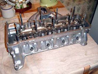
If you decide to start increasing the power of your engine not with zero filters and similar tricks, but seriously, then one of the first things we advise you to pay attention to is the revision of the cylinder head (cylinder head) and the intake manifold. This method has been known almost from the very beginning of the automotive industry. If you polish the rough channels and thereby at least partially remove the inlet resistance, you can achieve phenomenal results. Even simple channel polishing can add up to 10 HP, and if it is also wasted, you can increase the power even more significantly.
On different engines, the procedure itself, the type of collectors and the design of the cylinder head may differ. We are considering the revision procedure as a whole. As a starting material, we have a motor from the VAZ classics.
The method is really effective. It is a pity that, due to the high labor intensity, this is not done at the plant.
First you need to remove the head from the machine and disassemble it. We will not describe how to do this - most likely you yourself know, but no way there are enough books and other literature on the Internet.
After disassembling the cylinder head, it will not be superfluous to wash it. There is already everything to your taste. You can use chemistry, or you can do it in the old-fashioned way - kerosene, gasoline, solvent ... Then you can still walk with a brush on a drill, so that everything is absolutely beautiful.
To perform the procedures from the tool, we need the following:
- drill with the ability to adjust the speed
- drill
- flexible bar
- cones
- skins from coarse to finest
- rags, rags
- calipers
- exhaust valve and washer set - if you are bore over 32mm
- graphite grease
- teski

Channel groove
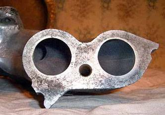
First, it is worth deciding in what order we will do everything. We recommend starting with the collector. when combined with the cylinder head, it is easier to remove a little in the latter than to buy a new manifold as a result.
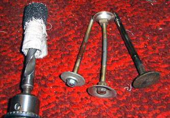
We collect the working tool: we wind a rag on the drill, and roll the skin on it, and we wind it with an overlap and more. For the convenience of performing the operation, we recommend clamping the collector in a vice.
Now insert the drill with emery into the drill and start sawing. The most difficult thing will be to overcome the first 5cm. As soon as they have passed we measure with the exhaust valve
Moving on! The collector has a bend, so you need to build the same tool on the rod. It is not worth pushing too much. the skin may slip. It itself should be making good progress.
As you can see, there is nothing complicated in this procedure.
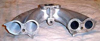
Collector after processing:
It will not be superfluous to polish the collector in the area of \ u200b \ u200bthe carburetor installation. It is convenient to do this with a drill brush.
Here's what happened (sorry for the quality of the photo):
We figured out the intake manifold. Now we turn to the head itself.
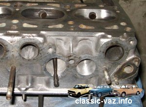
In order for the flow of the fuel-water mixture to enter the cylinders as easily as possible, it is necessary to remove the protruding transition at the junction of the intake manifold and the cylinder head. In the case of classic motors, this transition can have a step (protrusion) up to 3mm. To begin with, we are tedious to identify exactly where to grind. To do this, screw in all the studs for attaching the manifold into the cylinder head, take the grease, spread it on the surface around the channel and put the intake manifold on the studs.
This method allows you to clearly see where you need to grind. You can try to touch the saddle side with your finger, but many may not have enough toe length.
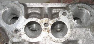
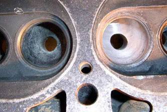
First, we also pass a little so that the valve fits. Then we move deeper. As soon as we reach the guide bushings, we wind up the skin a little and cut it off. It should look something like the photo below. On the left is the processed channel, on the right is the factory channel
The difference is literally striking.
After we have passed all the channels and cut the bushings into them, you need to polish the channel from the side of the saddle.This must be done very carefully so as not to damage the saddles. To do this, you can put a roller cutter on the drill. It is also necessary to make sure that the channel in front of the saddle is slightly wider than the rest of it.
It should look something like this, the difference is obvious
Thus, we got channels through which you can freely push the valve
With the release, the operations are the same. The only difference is that with standard valves you need to grind no more than 31mm.
We start with the collector. In contrast to the inlet, there should be a difference between the cylinder head and the manifold: the manifold must be of a larger diameter than the channel on the cylinder head.
Many restrict themselves to boring and polishing the intake manifold, and do not touch the exhaust. it is cast iron and therefore difficult to sharpen. Difficult but possible.
If funds allow, you can buy a 4-1 spider, it costs about $ 150.
The exhaust port in the cylinder head runs at a different angle than the intake, so it is more difficult to grind the bushings here. Do not be alarmed if you are walking hard.
The obtained result: on the left there is a flowed channel, on the right there is no. Although it can be seen so 🙂
Ideally, it is advisable to grind off the bushings on a cone. If you do not touch them, then they act like this into the channel:
Therefore, the ideal option would be to make them in the form of a cone:
First, the calculations. It is stupid to consider the area.
Carburetor weber holes 24x24,
(24 * 24 * 3.1415 / 2) * 2 = 904 mm2
The inlet channel, the narrowest part is where the guide sticks out.
(29 * 29 * 3.1415 / 4) - (14 * 14 * 3.1415 / 4) = 660 - 154 = 506 mm2
Inlet valve slot at highest lift:
33 * 3.1415 * 10 = 1037 mm2
From this it can be seen that the dimensions of the channel are significantly inferior in comparison with other narrow places in the intake tract. This is really only at the moment of full opening of the valve, but this time of almost full opening is overwhelming. In short, we must do it.
The maximum (I will show in the photo) is 34mm, you cannot squander a standard collector for a larger one, a 1mm wall remains.
We consider, taking into account the fact that we will turn the valve leg to 7mm, and cut the guide flush:
(34 * 34 * 3.1415 / 4) - (7 * 7 * 3.1415 / 4) = 909 - 39 = 870 mm2
it turns out, we increase the area of the narrowest place by 70%, good.
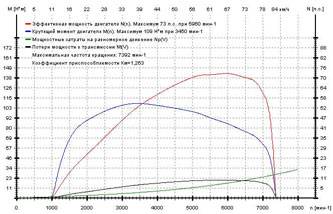
Let's start by measuring the power:
The absolute data is not clear, but the comparison is valuable information.
From the originator: Engine 1300, cylinder head 2101, power system - Webber 2101 23x24
Then the head is removed from the car, disassembled and washed.
Luxuriously naturally washed with carbon dioxide, but there was no fire extinguisher at hand. I washed it with ordinary kerosene, and later in the bathroom with a brush and powder. By the way, it is necessary not to forget to lubricate all the iron parts with oil (guides, saddles, bushings under the rocker) so that rust does not grab.
Another rumored way is when VD40 dissolves in an anti-freeze. water for the washer - a snow-white mixture comes out, which washes everything off simply.
By the way, it is better to twist the hairpins too, but so far they haven’t interfered with me.
A patient:
The guides are knocked out with a tool that I made from the bolt. Knock out simply and directly. outward fit 13.5, internal pin for direction - 8mm.
Now everything is ready for sawing channels. I would recommend starting with the collector, since there is more metal on the sides in the head, it is better to fit the head under the collector and not opposite.
Measurements: channels in the head 29, issue 27, in the manifold - 29, issue. manifold 29.
I bore it with sandpaper in a drill. The most effective head IMHO is a shaft (in my case, the drill is thick), on which a rag is wound, and on it is a strip of deto skin 20 cm long (everything is overlapped so that it does not jump off)
I used the coarsest sandpaper ON a RAG BASE that was only under my hand - this is 24. I made one channel in my head with it in 2 hours.
Also, for convenience, I made a set of washers on a stick (see photo), nominal (34mm) and
reduced diameter (33) and release kit. So well, very comfortable
control
the diameter of the channel, so as not to wave too much - such a washer should freely pass through the channel perpendicular to the axis, and not dangle very much.
Development - we wind the rags with the skin so that the “head” barely crawls into the hole, we begin to drill slowly, pushing everything further until the skin crumbles. Later, you can tear off a piece or turn the strip over and again. We control the diameter with a washer, the newest strip of skin and we went again.
It would be nice to have a tool for measuring the thickness of the walls, but I used tweezers with pieces of plasticine stuck to the ends.
Collector:
The sawn channels are strikingly different in cross-section from the non-sawn ones:
the collector is sharpened much harder than the head, due to the fact that you can only crawl from one side (from the side of the carb, you will not really stick through).
I managed to saw through the collector up to 34 only by 2/3, I had to remove the partition between the feces with a drill:
how lo
That's it, the washers pass freely:
it is necessary to dock the channels of the collector with the head. I tried various options with prints and so on. all this is difficult somehow. I slowed down on the plasticine - I sculpt around the circumference on the head, moisten the collector with water, press it with my hand, release it, cut off the squeezed plasticine inside the collector - you can clearly see where the head should go.
It is better to correct it separately before boring, since the skin distributes in all directions identically. You can correct it with a round ratfil, I just roughly cut the hole in the right direction, so that it moderately follows the contour of the hole in the collector. By the way, it is better to get out of the head a little more, for example 35, since there will still be a step, it would be better if it was not towards the head. But it is not necessary to expand on purpose - 35 and so it will turn out from the constant slicking with a skin through this hole.
And then we went. We grind moderately from the side of the collector, until the washer will not crawl to the hole under the guide, later it is better to sharpen from the side of the COP. Be careful with the saddles on this side. They are bored surprisingly quickly and simply, you can completely kill the place for a chamfer.
the difference is clear:
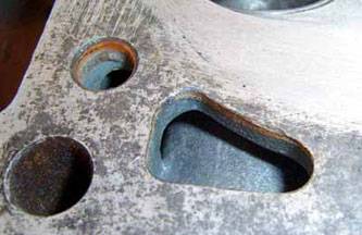
You can clearly see how the build-up around the hole under the guide is removed, which very loosely closes the channel:
The channels are all cut through, the head is washed. Do not forget to lubricate all iron parts with oil before washing, valve seats first!). To flush the cooling system, I used an electrolyte for the battery - i.e. sulfuric acid. He turned his head upside down, plugged all the holes and carefully so that acid would not get on the outer surface of the head (she still eats aluminum perfectly), poured it in, slowly shaking his head. Scale, plaque and rust dissolve one hundred percent in a few seconds, a full cycle of fiddling the head in acid, I do not think that it is necessary to stretch it for more than 5 minutes. We also carefully drain the acid.
The photo clearly shows the acid level - everything is dirty from above, from below it is virgin, spotless aluminum:
After that, immediately wash your head, you can in a solution of soda or washing powder and quickly dry it. For example, in the oven =)
intake manifold 34 (was 29), ports 34 (was 29), seats 33.5 (was 32.5)
the outlet channels at the saddle 28 (there were 27, half blocked by the protrusion under the guide), at the outlet from the head 30 (there were 27), the collector 30 (it was), the saddles 28 (were 27.5).
It took 0.5 m2 of skin No. 24 and somewhere the same amount of rags. The channel in the intake manifold took 2 hours, the intake in the head took 1 hour. In the head release - half an hour.
Cut the little ears in the cop:
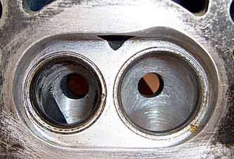
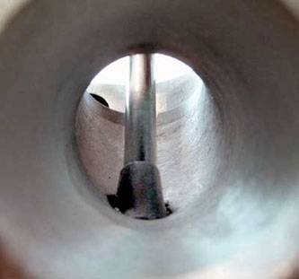
Results - looking at the entrance to the channel in your head, you can see the exit, in the unfinished one there is none:
Now about the guides. Having painstakingly weighed all the pros and cons, I decided to slow down on my own version and cut it hard-spatially
To begin with, I marked a line on it with a tap, along which it sticks out in the channel, and also along the entire perimeter (in order to simply sharpen and press it later) I drew it in front and back.
The point was to very much remove the protruding metal, and at the same time throw the channel from the inside (oil) to the maximum over the area and not touch, in general, its loaded side (break it), and with all this, everything is very aerodynamic to smooth out.
The inlet ones came out along the endings as follows:
As you can see, on the heel (the side on which the valve presses during operation), I actually did not touch the metal, so it hardly deforms.
With outlets, it is a little harder - there both heat dissipation and loading are stronger, and the direction of flow is greater. Therefore, the meaning is the same, but the amount of work is much less:
This is how the standard (a little bit of current) sticks out in the treated inlet:
like this - processed (though not completely withdrawn, this is bushy, I sharpened it for testing)
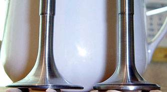
Modified the valve.
It was a bit hard, the chisel picks up very badly, even a victorious one. The new exhaust valve is actually not taken at all, I was recommended to take only used ones for revision, they sharpen better - the material is softer.
But later he squeezed it in the drill and finished the shape with a sandpaper - he takes it with a bang! Slowly, but surely, the metal is removed.
Here's what happened in the end:
(processed photo of the stock intake valve, reddish - removed metal)
I pressed in the guides with a made mandrel (metal bar, inside hole 11.0mm). Head in the oven up to 100 degrees, guiding into the freezer. You need to score carefully, but very quickly. Do not forget to remove the distribution studs, they will interfere (without removing the latter, in general, do not press in). At first, it just climbs later, they warm up, but they still climb normally. We knocked out, honestly, with still great effort. The main thing is to act faster.
Photo of an intake with a valve:
GTZH instead of 135/125 screwed 140/140. Rolled a little for a little break-in, measured it
As you would expect, there was an even increase in KM along the entire curve, an increase in the speed of the MM, an increase in KP.
The surcharge came out to 14 horses (well, or 12, considering that in his youth the motor had 75), which was previously calculated for.
Well, I think, by the final calibration of the carb, I'll take off one or two more horses (since it seems to be going fine anyway, without failures)
| Video (click to play). |
If all my research is squeezed into a single time gap and the aesthetics are thrown away (like polishing the head to shine), then you can easily keep within 5 working days. 1 day - removal-installation-adjustment, 3 days of sawing and 1 day of relaxation can be assigned to the valves.

