In detail: do-it-yourself repair of a ford mondeo 4 generator from a real master for the site my.housecope.com.
Self-repair of the generator and regulator
To remove the cover (2) of the bosch generator, unscrew the three Phillips screws (1), remove the wire b + from the threaded bolt (3) and push off the two retaining lugs (arrows).
The voltage regulator (2) is secured with two Phillips head screws (1). Position (3) denotes the rotor axis.
On the removed voltage regulator ((4), the illustration shows a new design), the length of the brushes (2) is indicated by arrows. Position (1) shows the contacts of the voltage regulator, (3) are the fastening bolts.
The illustration shows the measurement of the length of sliding electrographite contacts on a removed voltage regulator from bosch of an older design: the brushes should not be shorter than a = 5 mm.
Usually the generator does not require repair, except when replacing the generator brushes. More serious damage cannot be repaired with home remedies.
Checking the charging voltage
- Connect a volmeter between the generator thick red wire terminal and ground.
- Leave the engine running at medium speed.
- If the voltage regulator is working properly, the voltmeter should read 13.3 to 14.6 V.
- If not, check the brushes or replace the regulator.
- Otherwise, the generator itself is faulty.
- Disconnect the negative battery cable.
- Bosch alternators: remove battery cover at rear (where fitted).
- Disconnect the regulator from the generator. To do this, remove the two screws.
- Fold back the regulator so that the carbon brushes do not stick in the holders.
- Measure the protrusion of the brushes.
- The length of the new brushes is 13 mm; minimum length 5 mm.
- Valeo alternators: Unscrew both regulator fixing screws on the rear of the alternator.
- Pull out the regulator.
- Measure the length of the protruding brushes.
- If the remaining length is 5 mm, the brushes are worn out.
- Valeo generator brushes cannot be purchased separately; it is necessary to change the entire regulator.
| Video (click to play). |
Replacing the brushes on the new generation of bosch generators is no longer possible - therefore carbon brushes are no longer sold as spare parts. If they are worn out, the entire regulator should be replaced. The same can be said about the valeo generator; carbon brushes are not sold as spare parts - you need to buy a new voltage regulator if the old brushes are worn out.
However, such replacement is possible for older generation Bosch generators. This will require a soldering iron, solder and, in addition, knowledge of soldering.
- Remove the voltage regulator as described above.
- Unsolder the stranded flexible wires, pull out the carbon brushes.
- Remove pressure springs from old brushes and put on new ones.
- Solder stranded flexible wires.
- At the same time, apply a little tin and work quickly so that the wires do not suck in a lot of tin. Otherwise, they will become tough.
Hint: if the brushes are removed, you can check the copper slip rings at the same time (brushes walk on them). If deep traces of running-in are found on them, then you need to grind and polish them in an auto electrician's workshop.
- Disconnect the ground wire from the battery, otherwise there is a great risk of short circuit.
- 4-cylinder models: Remove the front pivot cover (where fitted) on the toothed belt guard.
- 5-cylinder models: remove the underbody protection from the engine compartment.
- 4- and 5-cylinder models: Disconnect alternator wires.
- Disconnect the earth cable, where available.
- Unscrew the clamping bolt on the alternator shim.
- Loosen and remove the V-belt or poly-V-belt
- Loosen and remove the hinge bolt while holding the generator.
- 6-cylinder models: remove the underbody protection from the engine compartment.
- Remove the V-belt (work described later in this chapter).
- Remove the connecting cable and cooling air guide from below.
- Loosen the mounting bolts, remove the generator.
Driving with a faulty generator
Hints: If the alternator or voltage regulator is not working, you can still continue driving as the battery can take over as a power source. During the day, its current reserve lasts for a long time, because the electronic ignition / injection control, as well as the electric fuel pump, need a minimum voltage. In addition, the battery is often only 2/3 charged. Depending on the capacity of the battery, you can drive at least another 5 hours. In winter, the general weakness of the battery is a complicating factor. In addition, the headlights must be switched on earlier.
Therefore, the motto should be to save current: you should not interrupt the trip unnecessarily, because the starter needs a lot of current. If possible, you should start "from the roll." Do not turn on heated rear window, heater and radio. It is more economical to handle the wiper. Drive at night without high beam and fog lights. Additionally, disconnect the cables from the generator and insulate them separately so that the battery cannot be discharged through a faulty generator or voltage regulator.
Generator removal report!
1. We jack up, unscrew the right front wheel, put it on a support for insurance. DO NOT LEAVE on the jack !! My friend's car fell from the jack on his head - he barely survived.
2. We open the hood, remove the decorative cover from the engine, remove the terminal from the battery (do not forget to stock up on the code for the radio - it will be locked).
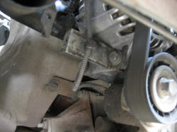
3. We look to the left of the engine, closer to the engine shield, the generator is visible in space: (sorry, bad photo, but the location is clear)
4. From the bottom, in the wheel niche, unscrew 3 bolts (10 and 8) and remove the dirt apron.
5. The following view opens:
6. The roller has a 15 hexagon (I don't remember exactly). We put the head on it, turn it clockwise through the extension cord as far as it will turn out (30 degrees), while it moves up to the right:
7. Holding the ratchet with my knee, I removed the belt from the roller, looking into the engine compartment from above. The first time I removed it from the generator pulley itself, but this is inconvenient
8. Throwing off the belt from the roller, you can easily remove it from the genes. So, they removed the belt, then:
9. Remove the plastic L-shaped cooling tube from the generator. There are two latches, it is removed by hand, but the third place of its attachment is the plate on the lower outer bolt of the generator, snap it off, there is a piston type:
10. Nearby, on the last photo, you can see a wire snapped to the bracket - you can shoot, you can not. The bracket itself can be easily removed with a half-unscrewed bolt, but until you see how, it is unlikely to work. In general, decide for yourself.
11. Unscrew the two bottom bolts. There, a 13 wrench. I used a ratchet and a short extension. It turned out to be more convenient for me from above, because the bottom of my ratchet was not able to work:
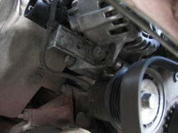
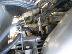
12... We remove all the wires (preferably together with the bracket) from the upper bolt, having previously released it on the heels of the revolutions. Everything is visible there, you will understand. Simply click the bracket upwards. Take everything aside. Try to unscrew the nut by 10, with which a thick wire from the battery is screwed to the gene. It's next to the 3-pin connector. You can safely crawl with a ratchet without an extension cord.
13. I didn’t manage to remove the connector blindly either the first or the second time - if you don’t see it, you don’t understand how to snap it off. I completely removed the gene and removed the connector already in the light.There is a crack, I put the blade of my penknife into it, it comes off.
14. So, unscrew the top bolt, catch the generator. It is quite heavy, 5 kilograms, strives to slip out and fall down, breaking the wires. Be careful.
15. After tormenting over the top, having washed, remembering the relatives of the designers, we pull out the gene. There are no recommendations here - see for yourself. I will say right away that it pushes back much easier - gravity helps
16. And this is me and my trophy (Like, hunted a lion in Africa)
Thanks to all,
Sincerely,
Alexey Doc Pribytkov.
P.S: By the way, I must warn you: DO NOT SCUT THE BELT BUCKLE FENDER. I specially tied a rag, otherwise the pants fall without a belt, it's hot in the jacket, and the buckle can scratch the wing
I will add my 5 kopecks about the removal of the genes (regarding cars with V6)
Firstly, as Alexei already said, in no case leave the car on a standard jack. I was in a hurry, I left it for the first time, just got out from under the car, and she sank down, (licking the thread on the jack nut).
Further, the operations are about the same, except for the following:
The V6 tensioner is squeezed out of the engine compartment, for which a 4-sided part of the ratchet (like size 3/8) is inserted into it, the belt is squeezed out and removed.
In the engine compartment, no more operations are available, everything is done from below, either through the wheel arch or from the pit.
Next, unscrew the genes bolts. Space there is catastrophically small, so I first removed the upper bolt, with which I have to suffer for a long time, then 2 lower ones. It's easier with them. And finally, the generator cannot be removed from above, it is removed through the wheel housing, after having thrown off the bone.
So by the way, and TIS advises.
Andry - Andrey
FM3 2.5 03 onwards hatch Jatco Ghia
04.02.2017 733
As a result, after the battery is completely discharged, your car will become stationary, and what is most annoying, this can happen at the most inopportune moment, for example, at night somewhere outside the city.
- Wear of brushes;
- Pulley worn or damaged;
- Short circuit in the stator winding;
- Damage to the voltage regulator;
- Backlash or destruction of the bearing;
- Break in the charging circuit wiring;
- Damage to the rectifier (diode bridge).
Today at Ford Master I will tell you how to perform generator repair Ford Mondeo 3 at home, this will save you the cost of buying a new generator.
- Puller;
- Screwdrivers;
- Hacksaw blade;
- A set of keys;
- Soldering iron;
- Spare parts: pulley, diode bridge, new brushes, bearing.
- The first step is to remove the generator.
- Next, you should clean the generator from dirt and dust. After you need to unscrew the pulley, if you do not have the necessary tool in order to unscrew the pulley, you can get out of the situation by contacting the nearest service station.
- Next, we proceed to unscrewing the studs, we use the key to “8” for this.
- The next step was to dismantle the diode bridge, a difficulty arose here, since spot welding was used in the manufacture of the generator, and it had to be cut down. You can saw with a Dremel, a file or a grinder, in this case a hacksaw blade was used. Also, in order to remove the diode bridge, you need to drill two rivets from the back cover.
- We dismantle the collector using a chisel, put it under spot welding, then carefully slightly separate the wire from the slip ring.
- Carefully align the wires and remove them using a slotted screwdriver.
- We remove the slip rings in turn.
- Then we remove the rear bearing, in my case it went pretty tight.
- Using a puller, press out the front bearing.
- We prepare bearings. We put the required amount of lubricant and proceed to assembly. We install the front bearing on the armature shaft. By the way, it is installed quite simply, practically by hand, after everything is assembled it will be clamped with a clutch.
Attention! After the collector rings have been pressed in and the armature wires have been soldered, I recommend walking with a cutter on a lathe for centering.
- Using a soldering iron, we solder the diode bridge to the stator winding, before that we carefully tin all the soldering points.
Subsequent assembly is carried out in reverse order.
The generator is a rather complex and high-precision unit. For its disassembly, troubleshooting and assembly, special equipment is required. Therefore, if you do not have sufficient skills in such work, in the event of a generator failure, we recommend that you contact a specialized workshop for its repair or replace the complete generator.
You will need: socket heads "13", "24", screwdrivers with flat and cross-shaped blades, barbs, a soldering iron, a puller for a rotor bearing, a hammer, a tester.
1. Remove the generator from the car (see Removal and installation of the generator).
2. Mark the relative position of the generator parts.
3. Clamp the alternator pulley in a vice, after placing spacers under it or winding an old belt, and unscrew the pulley retaining nut.
4. Remove the alternator pulley from the vise and remove the pulley from the rotor shaft.
NOTE.
The alternator pulley is fixed against turning on the rotor shaft only due to frictional forces after tightening the fastening nut to the required torque. There is no key in the connection.
6 .... and, using a screwdriver, remove the generator terminal.
7. Remove the four tie screws ...
8…. Using a screwdriver, remove the front cover of the generator and take out the rotor.
9. Remove the spacer ring from the rotor shaft.
10. Unsolder the three stator winding leads from the rectifier unit and remove the stator.
11. From the inside of the cover on the side of the slip rings, unscrew the three fastening screws and remove the brush holder assembly with a rectifier unit and a voltage regulator.
NOTE.
The stator leads must already be soldered from the rectifier unit in the process of removing the stator (see item 10).
12. Inspect the drive end cover of the generator. If during the rotation of the bearing you feel a play between the cages, rolling or jamming of the inner cage, damaged protective cuffs or there are grease drips, replace the bearing. If cracks are found in the cover, especially in the places where the generator is attached, replace the cover.
13. To replace the front rotor bearing, remove the four screws securing the pressure plate ...
15. Press the bearing out of the cover.
16. Using a mandrel of a suitable diameter, press the new bearing into the cover, applying force to the outer race of the bearing.
17. Check the ease of rotation of the bearing from the side of the slip rings. If during the rotation of the bearing you feel a play between the cages, rolling or jamming of the cage, damaged protective cuffs or there are grease drips, replace the bearing. If cracks are found in the cover, replace the cover with a new one.
18. Press the bearing off the rotor shaft and install the new bearing by applying force to its inner race with a mandrel of a suitable diameter.
19. Check the resistance of the rotor winding with a tester by connecting it to the slip rings. The resistance should be approximately 3-5 ohms. If the tester shows infinity, then there is an open circuit in the windings and the rotor needs to be replaced.
20. Check the short circuit of the rotor winding to ground. To do this, connect one probe of the tester to the pole piece of the rotor, and the other, alternately to the slip rings.
The measured resistance must be infinitely large, otherwise replace the rotor.
21. Check the stator windings for an open circuit, alternately measuring the resistance between all winding leads with a tester.If the measured resistance tends to infinity, the stator must be replaced.
22. Connect the test leads of the tester to the stator housing and alternately to each winding lead. The measured resistance should be very high (should tend to infinity). Otherwise, replace the stator.
23. Check the rectifier unit. To do this, connect one probe of the tester to the output of the stator phase winding, and the second probe to the air heatsink of positive diodes. By swapping the tester probes, measure the resistance. If the tester readings are the same in both cases, the rectifier unit is defective and needs to be replaced.
24. Check negative diodes in the same way.
25. Check the free protrusion of the brushes. If the brushes protrude from the brush holder by less than 3 mm, replace the brushes or brush holder assembly.
NOTE.
To replace the brushes, you will need to unsolder their wires from the brush holder terminals.
26. Assemble the generator in the reverse order of removal, orienting the generator covers and stator housing according to the previously made marks.
NOTE.
Before installing the cover from the side of the slip rings of the rotor, sink the brushes and fix them in this position by inserting a pin into the hole in the cover (for example, an unbent paper clip). After assembly, remove the pin.
Such a question for a car with 2-liter engines has a weak point - it is a generator, diodes are on. How is this situation in 1.6 engines? How long do generators run and break down just as often?
At the moment, I have S-Max, with a 2-liter engine, a few days ago the generator was covered, the diode bridge burned out. The same trouble overtook a lot of max drivers 06488 / # comments, and since the 2-liter engines in S-Max, FF2 and FM4 are the same, this prompts various thoughts, and one friend who sells spare parts for Ford said that the engines are 1 , 8 and 2.0 Ford are "sick" with generators (in demand).
That's why I wanted to know how the "genes" of the 1.6 engine behave, how much are they being cared for, and are there any complaints about them in general?
A similar situation, the no-charge light comes on. I checked the charging 14.5 stably at all speeds, I can not understand why the brain does not see the problem.
Help who knows.
the service said do not bother it will go out! probably meant when it burns out
The battery is fully charged, I periodically put it on charge, but the lamp lights up and does not depend on the battery charge level.
running on my car is 82t. , new gene. I don’t know exactly how much, I think around 15tr.
Shir! I explain again. If after starting the engine the “battery” icon lights up, and after 20-40s it goes out, this means that during the movement (which preceded the start) the battery did not receive sufficient charge from the generator, one of the reasons is a large number switched on energy consumers (light, radio, air conditioner, heating, etc.), this is especially true when consumers are switched on with the engine off (at least on xx). Even with a fully charged battery, it will gradually discharge. After starting the engine, the battery starts actively take charge - this is indicated by the control lamp.
All of the above does not apply to a constantly lit or blinking control lamp.
Since 2004, almost all Fords have been equipped with an intelligent relay controlled by the PCM engine control unit. If there is no control from the PCM, then the relay goes into limited mode and generates an average voltage value U = 13.54 V. This can be checked in test mode on the instrument panel:
Ignition = OFF.
Press the OK button of the on-board computer and hold
Ignition = ON without releasing the OK button.
We continue to hold the OK button until the inscription TEST appears on the instrument panel display.
By briefly pressing the OK button, scroll through the test mode menu until the inscription b12.4,
bU12.4
Battery12.4
Battery = 12.4
The labels differ depending on the level and model of the shield.
We start the car and look at the value of the on-board voltage.
If it's not difficult, you can help with advice:
2011 Mondeo car 4
Foreword: with a cold snap, I began to notice that in the morning, 5-10 minutes after the car was running, the radio tape recorder reboots (good non-standard Chinese)
I thought about it - I began to look closely at the behavior of electrical equipment and noticed strange features:
1. When the engine is running (both at idle and at 2-3 rpm, flickering of bulbs is noticeable - illumination of the legs, illumination in the outside mirrors, illumination of the rear displacement zone
2. When you turn off (just turn off.) A large load (heating the windshield, the electric heater and the pump of the ESP system), a half-second drop in the spill occurs in the on-board network - as a result of which the radio tape recorder falls
the process of the fall of the naprugi filmed on video
Can you tell me which way to dig? Generator? Voltage regulator? Diode bridge? Bad weight?
The installed generator is not repaired; if it fails, it is replaced with an interchangeable generator, which is covered by the warranty, like a new one. However, in most cases it is possible to have the defective generator checked by a Bosch service center before installing a new generator. This may reveal that the generator can be repaired if the faults are minor.
If you suspect there is a problem with the alternator, take the following measurements before removing:
1) check the charging current wire:
- disconnect the negative wire from the storage battery and disconnect the connector from the back of the generator or unscrew the wire;
- reconnect the wire to the storage battery and turn on the ignition;
- connect the voltmeter to ground and any terminal of the multi-pin connector; when connected to all terminals, the voltmeter should show a value approximately equal to the battery voltage, otherwise the generator or voltage regulator is faulty;
Rice. 286. Checking the current output by the generator
2) current output (to check the 30 A regulating resistor, in addition to an ammeter, you must also have a voltmeter, they are necessary to create the electrical circuit shown in Fig. 286):
- turn on the headlights and the heater motor;
- set the engine speed to 3000 min-1 and change the resistance to increase the current consumption;
- the rated current of the three-phase current generator (70A) must be achieved, and the voltage must not fall below 13 V;
- turn off the ignition and consumers and disconnect the measuring instruments;
3) checking the voltage drop in the "positive" part of the charging current circuit:
Rice. 287. Checking the voltage drop in the "positive" part of the charging current circuit
- create an electrical circuit as shown in fig. 287;
- turn on the headlights, start the engine and measure the voltage drop;
- Bring the engine speed to 3000 min-1 and take the voltmeter reading. If the measured voltage exceeds 0.5 V, then there is a high resistance in the “positive” part of the generator, which should be eliminated;
- turn off the ignition and headlights;
4) checking the voltage drop in the "minus" part of the charging current circuit:
Rice. 288. Checking the voltage drop in the "minus" part of the charging current circuit
- create an electrical circuit as shown in fig. 288, start the engine, turn on the headlights and measure the voltage drop;
- Bring the engine speed to 3000 min-1 and take the voltmeter reading. If the measured voltage exceeds 0.25 V, then there is a high resistance in the “minus” part of the generator, which should be eliminated;
- turn off the ignition and headlights, disconnect the test wires and voltmeter;
5) checking the regulator based on the regulation voltage:
Rice. 289. Checking the regulator based on the regulation voltage
- connect voltmeter and ammeter according to fig. 289;
- start up the engine and measure the regulation voltage;
- Bring the engine speed to 3000 rpm and observe the ammeter. As soon as the value shown by the ammeter drops to a value within 3-5 V, take a reading on the voltmeter, the voltage shown should be in the range of 13.7-14.6 V. If the value on the voltmeter is outside the specified range, the voltage regulator is faulty.
Service manual Ford Focus, Fusion, Mondeo
Purchase and sale of used cars Ford Focus, Fusion, Mondeo.
Repair and maintenance Ford Focus, Fusion, Mondeo.
Ford Mondeo is equipped with a Bosch, Mitsubishi or Ford three-phase generator. Depending on the model and equipment, generators of different capacities are installed.
The generator is driven by the crankshaft via a V-belt. In this case, the rotor, with the help of the excitation winding, rotates inside the stationary winding of the starter at a speed twice the speed of the engine.
The excitation current flows through the graphite brushes and slip rings into the excitation winding. This creates a magnetic field. The position of the magnetic field in relation to the stator winding constantly changes in accordance with the rotation of the rotor. As a result, an alternating current flows in the stator winding.
As the battery is charged from the generator, the three-phase current is converted through rectifiers mounted on the diode board to direct current. The voltage regulator changes the charge current by turning the excitation current on and off according to the state of charge of the battery.
At the same time, the regulator maintains the operating voltage constant at about 14 V, regardless of the speed.
Generator Safety
To avoid damage to the device, follow the safety instructions when working on the generator. Disassembly and repair of the generator should be carried out in a specialized repair shop.
• If an additional battery is connected (for example, to help with starting), be sure to make sure that the same pole of the Oldies is connected to each other.
• When connecting the charger, the charger wires must be connected to the appropriate battery terminals. Disconnect the ground wire and the positive wire during the battery charging process.
• The engine must not run without a battery.
• Never short-circuit generator and voltage regulator terminals.
• Never switch generator poles.
Important! Disconnect the ground wire (-) from the storage battery.
Attention! As a result, data in electronic storage devices such as an engine fault memory device or a radio code is erased. Carefully read the “Removing and installing the battery” section before disconnecting it.
Removal in cars with a carburetor engine
• Remove the air filter.
• Unscrew the bolt of the wire holder on the outlet of the suction pipe and remove the wires from the generator.
• Unscrew the upper mounting bolt of the generator.
• Mark with paint the position of the right front wheel relative to the hub. As a result, the balanced wheel can be mounted in the same position. Loosen the wheel nuts while the vehicle is on the ground. Place the car at the front on stands and remove the right front wheel.
• Remove the inner wing of the car.
• Remove the belt pulley cover and loosen the V-ribbed belt, remove only from the alternator belt gear.
• Remove the tie rod head.
• Unscrew the lower mounting bolt and take out the generator through the wheel well.
Installation
• Install the generator, screw on the lower mounting bolt without tightening it.
• Lower the vehicle to the ground.
• Tighten the upper alternator mounting bolt to 50 Nm.
• Raise the vehicle.
• Tighten the lower mounting bolt to 50 Nm.
• Fit the V-belt and the belt pulley cover.
• Fit the tie rod head.
• Fit the inner wing of the vehicle.
• Install the right front wheel so that the markings made when removing are aligned. Pre-lubricate the rim seat surface on the wheel hub with bearing grease. Screw on the wheel. Lower the vehicle to the ground and tighten the wheel nuts in a crisscross pattern to 100 Nm.
• Connect the electrical wires to the generator and screw the wire holder to the outlet of the suction pipe.
• Fit the air filter.
• Connect the battery ground wire (-).
• Set the clock to the current time.
• Set the anti-theft code of the radio.
Removing the generator in vehicles with a turbodiesel
• Place the vehicle on stands.
• Remove the bottom cover of the engine.
• Remove the alternator V-belt.
• Remove the charge air cooler.
• Disconnect the multi-pin connector from the generator, unscrew the thick wire.
• Unscrew and remove the generator.
Installation
• Install the generator and tighten with a torque of 50 Nm.
• Put the multi-pin connector on the generator, screw on the thick wire.
• Place the vehicle on stands.
• Fit the V-belt and tighten.
• Fit the lower engine cover.
• Lower the vehicle to the ground.
• Connect the battery ground wire (•).
• Set the clock to the current time.
• Set the anti-theft code of the radio.
Checking the alternator charging voltage
• Connect a voltmeter between the positive and negative poles of the battery.
• Start the engine. During the start, the voltage should drop to 9.5 V.
• At 3000 rpm, the voltage should be between 13.0 and 14.5 V. This is an indication that the alternator and governor are running.
1 - Screws
2 - the Cover
3 - Retaining protrusions
4 - Screws
6 - Projection for connection with the car body
G2 - Generator
The figure shows the B0SCH generator
The voltage regulator is built into the carbon brush holder. Carbon brushes can be changed individually, but this requires a certain skill. The carbon brushes of the generator wear out rather slowly, on average after driving about 120,000 km. It is advisable to prudently replace them a little earlier.
Removal (Bosch alternator)
• Remove the generator.
• Unscrew the screws -1-, disconnect the spring clips and remove the protective cover -2-.
• Unscrew screws -4- and remove adjuster -5- to the side.
• Replace the carbon brushes by removing the wire.
• Check the slip rings for wear, if necessary, slightly bore them and polish them clean (work in a repair shop).
• Insert carbon brushes -A- and springs -B- into brush holder -C- and solder the connections.
• To prevent the solder from rising too high on the multi-wire wire when soldering new brushes, use pliers to wrap around the end.
Attention! When the solder grips the end of the multi-wire too much, the wire becomes stiff. and carbon brushes are unusable.
• Install the voltage regulator and screw down. When installing the regulator, make sure that the lug for connecting to the body -5- is in contact with the regulator.
• After installing new carbon brushes, check their ease of movement in the brush holders.
• Put on and screw on the generator casing.
• Install the generator.
Attention! Carbon brushes can only be replaced in conjunction with a voltage regulator.
• Remove the generator.
• Unscrew the four screws of the regulator and remove it.
Installation
• Insert and screw on the -1- adjuster.
• Pull out the locking pin -2-.
Note! The spare regulator has a locking pin to keep the carbon brushes in their original condition.
Can you tell if you can remove the generator brushes on the 2008 Mondeo 4 without removing the generator?
extremal198002, then you have to unambiguously remove it? Not aware of a lot of hassle?
fin8170, throw off the belt, disconnect all wires and unscrew the three nuts
gnostic2070, in principle, nothing complicated, as I understand it !? How is the belt removable? Is there a tensioner in there?
fin8170, there is a tensioner, you need to unscrew the wheel and loosen the tensioner
gnostic2070, you will not prompt there is something to replace the brushes not original
fin8170, I won't tell you here, sorry)
gnostic2070, I understood everything, thank you very much for the information
I didn’t understand one thing. why remove the wheel. There you can reach the tensioner with your hand. and look carefully at the "chocolate" ie on the gene control unit .. I will not argue - I removed the gene, but together with the brushes I also changed the dampener. for some reason it seems to me that the chocolate can be unscrewed and so
| Video (click to play). |
leash, that's exactly what to reach, and if you remove the wheel, you can work calmly, everyone chooses as it is convenient for him, but I do not impose my opinion)

