In detail: do-it-yourself repair of the g221 generator from a real master for the site my.housecope.com.
Generator Г 221 (G 221 A, B), the first generator, which was installed on the grandfathers of the Zhiguli, models VAZ 2101 and 2102. Reliable and unpretentious to operating conditions, in various climatic conditions of our former large state. The generator is arranged according to the classical scheme of a three-phase synchronous machine. Self-excited generator, which is very important when starting the engine by towing and a completely discharged or missing battery.
A three-phase winding that generates an alternating voltage, after being converted by a built-in bridge rectifier, is capable of delivering direct current up to 42A to the consumption network. Such a current Generator Г 221 able to give already at 1400rpm.
Three-phase bridge rectifier on six diodes of different polarity. In the first models of the generator, the negative diode assembly was located directly in the back cover generator G 221... Subsequently, this unit was redesigned and in subsequent designs, the rectifier unit had the design of a separate unit. Blocks of this design are installed on all modern domestic generators.
End shields, cast from aluminum alloy, are at the same time the generator housing. The generator excitation system is a brush minus brush of the excitation winding connected to the generator body. The excitation voltage is applied to the excitation coil through slip rings and a brush mechanism and is regulated by an electromechanical voltage regulator.
Repair of the G-221 generator
The generator of a VAZ car is disassembled to completely check the health of its elements and replace the faulty stator, rotor, its bearings and rectifier unit.
| Video (click to play). |
To disassemble the generator, you will need: keys "for 8", "for 10", "for 13" and "for 19", socket heads "for 8", "for 10" and "for 19", a knob, a torque wrench, a screwdriver , vernier caliper, hammer, mandrels for pressing and pressing generator bearings, generator pulley puller.
1. Unscrew the screw securing the generator brush holder and remove the brush holder.
2. Unscrew the alternator pulley retaining nut by clamping the alternator pulley in a vise through the belts (use a regular alternator belt and some kind of large-section drive belt, for example, from a truck).
3. Using a puller, press the pulley off the generator rotor shaft.
4. Remove the alternator pulley key.
5. Unscrew the four nuts securing the generator cover from the side of the slip rings (rear cover), remove the spring washers.
6. Remove the back cover of the generator together with the stator.
7.Remove the rotor and rear bearing assembly from the generator front cover. Do not lose the spacer ring fitted to the rotor shaft (arrow).
8. Unscrew the nuts securing the front bearing caps by filing the bared ends of the screws.
9. Remove the screws, front bearing inner and outer caps.
10. Press the front rotor shaft bearing out of the generator front cover using a mandrel of the correct diameter.
11. Unscrew the three nuts securing the leads of the stator windings from the rectifier unit, remove the spring washers, remove the bolts with insulating spacers.
12. Remove the tip of the wire from the terminal block "67" inside the back cover of the generator, pushing it with a screwdriver, and disconnect the back cover and stator.
13. Unscrew the nut securing the output "30", remove the lock and flat washers, as well as the nylon insulating spacer.
14. Remove the rectifier unit from the generator back cover.
15. Using a puller, press the rear bearing off the rotor shaft.
16. Before installation, check the condition of the generator brushes and measure their protrusion from the brush holder (should be at least 12 mm).
17. Assemble the generator in the reverse order of disassembly.
NOTE
After tightening, tighten the nuts of the screws that secure the front bearing caps (see point 8) to prevent them from loosening.
This article details the process DIY VAZ 2101 generator repair - disassembly, cleaning, replacement of non-working parts, assembly and installation. The generator will be repaired on the 37.3701 model (it is almost identical to the G222 model).
- Andycar bearings.
- Generator capacitor.
- Diode bridge.
- Nuts 8 (4 pcs).
- Relay regulator (if there is a need to replace it).
I decided not to change my regulator relay, because its condition suits me perfectly.
- A universal puller for removing the bearing, as an option, you can use a rod puller, but I warn you, this is very inconvenient.
- Also find a good metal brush and cloth backed sandpaper.
- Hammer.
- WD-40.
- Standard set of wrenches and screwdrivers.
This is how it looked generator VAZ 2101 before repair, remember it like this, because after the bulkhead it will change beyond recognition 🙂
DIY VAZ 2101 generator repair: disassembly, cleaning, replacement of parts
1. The first step is to clean the generator from dirt, dust, oil, in short, from everything that has accumulated on it over many years of operation.
2. Unscrew the pulley nut, to do this, lay the generator so that its pulley rests on the floor, then put the key on “19” on the nut. Holding the pulley with a wrench from turning, you need to apply several strong and accurate blows with a hammer to the wrench. It is unlikely that it will be possible to clamp the pulley “tightly” by hand, but this will be enough to “rip off” the nut for free loosening.
3. Using a “10” wrench, unscrew the four tie rod bolts that assemble the generator into one piece.
4. Take a chisel and knock out the key (see photo above), for this you need to install the generator so that the shaft is on top. Place the chisel on the key and start knocking it out by hitting the chisel with a hammer. 5. After the key is knocked out, remove the generator front cover. In case it goes tight, try knocking out on weight.
Read also:
6. Now remove the relay regulator from the generator.
7. Using the hole under the relay, knock out the rotor, for this you can take a drift. While knocking out, rotate the rotor constantly so that it does not warp.
8. Using the socket at “8”, unscrew the three fastening nuts of the stator, as well as the diode bridge. Here, attention must be paid to the bolts, if they are turned, hold them with pliers on the back side.
DIY VAZ 2101 generator repair: disassembly, cleaning, replacement of parts
9. It's time to remove the stator, before I did it I sprayed the joints with WD-40 fluid. When everything is a bit sour, we arm ourselves with a hammer again and begin to knock it out.During execution, be extremely careful and careful not to damage anything. When the stator is removed, you need to get the diode bridge. Unscrew the capacitor and press out the rear rotor bearing using the universal puller mentioned at the beginning of the article.
10. Now unscrew the front cover and pull-off plates. The locked bolts that are installed there can be damaged, so at the beginning I did not in vain mention that it is necessary to buy four nuts for “8”. To prevent the bolts from turning when unscrewing, clamp them with pliers on the other side.
11. Remove the plates, then the bearing must be extruded through the mandrel.
As you can see generator VAZ 2101 now it has been completely disassembled, now everything needs to be cleaned, washed, scrubbed, etc. I will not go into details, since I think how to do this is so clear. You will need a metal brush, sandpaper and a knife.
Draw your attention on the fact that since 1996 the place of withdrawal of contact 61 has changed.
My old diode bridge is "old-style", the differences are clearly visible in the photo, on the old one the contact is located on the wire, and on the new one it is soldered into the diode bridge.
Press the bearings into place in the same way, through the mandrel. An important point - when pressing the rear bearing onto the rotor, you need to put the mandrel only on the inner bearing race, while pressing the front one you need to do the opposite - put on the outer one. If you ignore this rule, you can damage the bearing.
You may be interested in:
The rest generator assembly is carried out in the reverse order. Those who had an old-type diode bridge installed will have to tinker with pin 61, it does not fit well into the hole in the back cover. Personally, nothing else came to my mind other than just finishing the hole with a file.
Advice : I recommend sanding the seating plane of the capacitor, this will improve the contact and make it more stable. The rotor is again hammered with a hammer and light blows. At the end of the assembly, do not forget to lock the bolts with a chisel.
This completes the repair of the VAZ 2101 generator, it remains to install it on the car and test it in action. I hope my detailed photo report helped you. Thank you for attention! Those who wish to supplement the article can use the comment form.
Profile
Group: Asset
Posts: 9
User #: 18162
On the forum since: 09/12/2010
Has warnings:
(0%)
Profile
Group: Old people
Posts: 2693
User #: 22022
On the forum since: 11/28/2011
Has warnings:
(0%)
Profile
Group: Assistants
Posts: 182
User #: 14815
On the forum since: 08/13/2009
Has warnings:
(0%)
Profile
Group: Old people
Posts: 2693
User #: 22022
On the forum since: 11/28/2011
Has warnings:
(0%)
It is noteworthy that this harmful phenomenon should not be attributed to the prescription and to "type A shitty machines of the past." Some modern rotors are assembled (generally in "g") in fit, on a large (!) Lathe "knurling" and even a side impact when the rotor (removed) falls, for example, one beak in the diagonal can be freely displaced from the table (a little) forever upsetting the balance. For this reason, the planned “weakness” of modern generators, I stopped doing rotor repairs altogether. And on some, it has already become dangerous to change the bearings. Literally the day before yesterday I was dealing with a BMW 525i on which the bearings were replaced before the sale. two days of work at the new Maladogo Active boy (a la slipper on the floor) and the generator is full of a wedge before the fire. So I understand that in the case of such high-speed transmissions to the rotor, it would not hurt to check that rotor for balance already relatively from the newly installed bearings.
And on winding up the winding up to 4 Ohms on the "classic" this is an ordinary case for me, as well as winding up to 3.3 Ohms when installing the "06-01" x internals in the "07 (9)" generator (with built-in PP). Sometimes they bring everything in a heap. then help out. then they will rearrange ..the fathers rearranged it and lay in the corner of the garage. As if already there are almost no "kopecks-six", but developments are still required. Not hitting the voltage when winding up "extra" turns can be attributed to anything. for example, to coincide with a weak mass on an engine that has a weak PP. but you never know. whoever wants to bother with the "oldies" - in the trash and that's all.
The generator is disassembled for a complete check and validity of its elements and replacement of faulty stator, rotor, its bearings and rectifier unit.
You will need: keys "for 8", "for 10", "for 13" and "for 19", socket heads "for 8", "for 10" and "for 19", a knob, a torque wrench, a screwdriver, a vernier caliper, hammer, mandrels for pressing and pressing generator bearings, generator pulley puller.
1.Loosen the screw securing the generator brush holder and remove the brush holder.
2. Unscrew the alternator pulley fastening nut by clamping the alternator pulley in a vise through the belts (use a standard alternator belt and some kind of large-section drive belt, for example, from a truck).
3.Using a puller, press the pulley off the generator rotor shaft.
4. Remove the alternator pulley key.
5. Unscrew the four nuts securing the cover from the side of the slip rings (back cover), remove the spring washers.
6. Remove the back cover of the generator together with the stator.
7. Remove the rotor and rear bearing assembly from the generator front cover. Do not lose the spacer ring fitted to the rotor shaft (arrow).
8. Unscrew the nuts securing the front bearing caps by filing the bored ends of the screws.
9. Remove the screws, front bearing inner and outer caps.
10. Press the front rotor shaft bearing out of the front cover using an appropriate diameter mandrel.
11.Unscrew the three nuts securing the stator winding leads from the rectifier unit, remove the spring washers, remove the bolts with insulating spacers.
12. Remove the tip of the wire from the terminal block "67" inside the back cover of the generator, pushing it with a screwdriver, and separate the back cover and stator.
13. Unscrew the nut securing the output "30", remove the lock and flat washers, as well as the nylon insulating spacer.
14. Remove the rectifier unit from the generator back cover.
15.Use a puller to press the rear bearing off the rotor shaft.
16. Before installation, check the condition of the generator brushes and measure their protrusion from the brush holder (should be at least 12 mm).
17. Assemble the generator in the reverse order of disassembly.
After tightening, tighten the nuts of the screws that secure the front bearing caps (see step 8) to prevent them from loosening.
Rules for checking and operating the generator
When operating, maintaining and repairing the generator, the following rules must be observed, violation of which may result in damage to the voltage regulator or rectifier valves. The negative terminal of the storage battery must always be connected to ground, and the positive terminal must be connected to the generator terminal.
An erroneous re-insertion of the battery will immediately cause an increased current through the generator valves and malfunction. It is not allowed to operate the generator with consumer wires disconnected from the clamp (especially with a disconnected battery).
This will cause dangerous voltage increases across the valves and they can be damaged. It is forbidden to check the generator's performance "for a spark" even by short-term connection of the generator clamp to ground or a plug. In this case, a significant current flows through the valves, and they break through. You can only check the generator using an ammeter and a voltmeter. It is forbidden to check the charging current circuits with a megohmmeter or a lamp supplied with a voltage of more than 36 V. If such a check is necessary, then first disconnect the wires from the generator and the voltage regulator.
The quality of the stator insulation with increased voltage should be checked only on the stand and always with the phase winding leads disconnected from the valves. When electric welding of units and parts of the car body, disconnect the wires from all terminals of the generator and the battery.
Increased operating noise
Generator noise is usually caused by wear or damage to the armature bearings. The front bearing is usually the first to fail due to the large loads placed on it, for example, due to excessive tension on the drive belt. Replacing bearings is usually straightforward, although this will require almost complete disassembly of the generator.
After disassembly, you should pay attention to the condition of the bearing bores in the housing and the front cover of the generator. It is rare, but it happens that these holes are worn out or deformed. If the total wear in the bore and in the bearing turns out to be greater than the gap between the armature and the stator, then the armature touches the stator poles during rotation, which is unacceptable. It is required to replace not only the bearings, but also the housing or the front cover of the generator. For generators of foreign cars, you can pick up a domestic bearing (bearings are chosen according to the outer and inner diameters, as well as width).
For example, for many Bosch generators, bearing 80203 from the Volga gearbox input shaft support is suitable for the front armature support, and 180201 bearing from VAZ, Moskvich and Tavriy generators can be used as the rear one.
Generator does not supply charging current
Open or interturn short circuits in the armature and stator windings
In this case, the generator will also not generate current. Generally speaking, breaks and turn-to-turn short circuits in the stator winding and the armature excitation winding are determined using an ohmmeter, but sometimes breaks can be detected after disassembly during an external examination. Particular attention should be paid to the condition of the soldering points of the excitation coil leads to the slip rings, the connection of the brush wires to the contact plates, etc. If a defect is found, then it is eliminated with a soldering iron. In the event of a short circuit of the windings on the case, most likely it will be necessary to replace the armature or stator assembly, or even the entire generator.
Rectifier unit failure
If the brush assembly is working properly, there are no breaks and short circuits in the electrical circuits and windings, and the generator still does not produce a charging current, then the culprit is most likely the rectifier unit. Defective diodes - the main elements of the rectifier unit - can either not pass current at all (in the event of an open circuit), or pass current in both directions (in the event of a short circuit). A failed rectifier unit must be replaced.
Malfunctions of the voltage regulator
generator operation fault voltage
Defects in the voltage regulator are manifested in the fact that the generator gives a large charging current, and the battery is systematically recharged (the electrolyte "boils"), or the current, on the contrary, is too weak, or even absent altogether. Incidentally, voltage regulator malfunctions are one of the most common failures in a generator set system. The operation of the regulator can be checked on the vehicle. Let the engine run for 15 minutes at medium speed, then turn on the headlights and use a DC voltmeter to measure the voltage between the output terminal and the generator ground. If the regulator is working properly, then the measured voltage should be in the range of 13.5-14.5 V. Otherwise, the regulator will have to be replaced.
Generator parts
1 - "negative" brush; 2 - brush holder; 3 - "positive" brush; 4 - block of the neutral wire plug; 5 - insulating bushings of the contact bolt; 6 - rectifier unit; 7 - contact bolt; 8 - stator; 9 - rotor; 10 - inner washer of bearing fastening; 11 - cover from the drive side; 12 - fan assembly with a pulley; 13 - outer washer of bearing fastening; 14- front rotor bearing; 15 - a distance ring; 16 - coupling bolt; 17 - clamping sleeve; 18 - cover from the side of slip rings; 19 - buffer sleeve; 20 - bushing
1. Clean and blow out the generator with compressed air. Unscrew the screw and remove the brush holder 2 with brushes.
2. Remove the alternator pulley using special tool 67.7823.9504. To do this, lock the pulley with the gripper included in the tool kit, unscrew the pulley fastening nut and press the pulley with a puller. Remove the key and tapered pulley washer. The tool kit 67.7823.9504 includes a conventional puller and gripper. The latter consists of two steel half rings, which are embedded in the pulley stream. The half rings have the same cross section as the alternator drive belt. On the one hand, they are pivotally connected, and on the other, they are equipped with levers that are compressed by hand when the nut is unscrewed and the pulley is removed.
3. Unscrew the nuts of the four tie bolts 16 and detach the rear cover 18 with the stator 8 and the rectifier unit 6 from the front cover 11 with the rotor 9.
4. Remove the rotor with spacer ring from the front cover bearing.
5. Unscrew the nuts of the screws connecting the ends of the valves with the terminals of the stator winding, remove the plug of the central terminal of the stator winding from block 4 and disconnect the stator from the back cover.
6. Unscrew the nut of the contact bolt 7 and remove the rectifier unit 6 from the cover.
1. The generator is assembled in the reverse order of disassembly.
2. The misalignment of the holes in the legs of the generator covers should be no more than 0.4 mm. Therefore, when assembling, it is necessary to insert a special gauge into these holes, having a diameter of 12 mm on one side and 22 mm on the other.
3. The conical pulley spring washer should be in contact with the nut with its convex side. Tighten the pulley nut with a torque of 38.4–88 N · m (3.9–9.0 kgf · m).
If the brushes are worn out and protrude from the brush holder by less than 5 mm, then replace the brush holder with brushes.
Before installing the brush holder, blow out the carbon dust nest and wipe off the oil mixed with coal dust.
1. To remove the defective bearing from the cover on the drive side, unscrew the nuts of the screws tightening the bearing retaining washers, remove the washers with screws and press out the bearing using a hand press. If the nuts of the screws do not loosen (the ends of the screws are bent), then cut off the ends of the screws.
2. Install a new bearing in the generator cover only if the bearing bore is not deformed and its diameter does not exceed 42 mm. Otherwise, replace the bearing cap.
3. The bearing is pressed into the cover using a press and then clamped between two washers tightened with screws and nuts. Open the ends of the screws after tightening the nuts.
4. When replacing the rotor bearing from the slip ring side, the cover must be replaced at the same time, since if the bearing is damaged, the seat in the cover is usually damaged as well. The bearing is removed from the rotor shaft with a puller and pressed onto the press.
In modern generators with a rectifier unit, in case of failure of one of the valves, the entire rectifier unit must be replaced.
For generators of old releases, "positive" valves were pressed into a separate aluminum plate (radiator) and "negative" ones - into cover 1 (see Fig. Generator G-221). With such generators, if one or more "positive" valves are damaged, it is necessary to replace the radiator together with the valves.
Generator G-221
1 - cover from the side of slip rings; 2 - rectifier unit; 3 - bolt of fastening of the rectifier unit and the conclusions of the stator winding; 4, 5 - slip rings; 6 - rear ball bearing; 7 - rotor shaft; 8 - insulating bushings; 9 - screw for fastening the brush holder; 10 - positive contact bolt (terminal "30"); 11 - insulating sleeve of the contact bolt; 12 - plug of the central output of the stator winding; 13 - brush holder; 14 - negative brush; 15 - positive brush; 16 - hairpin for fastening the generator to the tensioning bar; 17 -pulley impeller; 18 - pole tip of the rotor from the drive side; 19 - generator drive pulley; 20 - pulley fastening nut; 21 - a distance ring; 22 - front ball bearing; 23 - cover from the drive side; 24 - rotor winding frame; 25 - rotor winding; 26 - insulation of the stator slot; 27 - stator; 28 - stator winding wedge; 29 - stator winding; 30 - pole piece of the rotor from the side of slip rings; 31 - tie bolt; 32 - buffer sleeve; 33 - bushing
1. Damaged "negative" valves, pressed into the cover 1 of the generator, can be replaced with serviceable ones of the same polarity. To do this, carefully press out the faulty valve on a press (1 - punch А.76027, 2 - support А.76029, 3 - base plate А.76032). Do not knock it out with a hammer, so as not to spoil the hole for the valve and damage other serviceable valves pressed into the cover.
2. Carefully, without distortion, press the new valve into the cover also on the press (1 - punch А.76027, 2 - "negative" valve, 3 - support А.76013, 4 - generator cover). Never press in the valve with hammer blows.
3. The pressing force must act on the valve body, as shown in the figure (arrows indicate the places on which the A.76028 punch should act when pressing in).
4. The valves are pressed against the flange against the generator cover. For valves with an unrolled collar near the flange, a gap of 0.1–1 mm between the valve flange and the cover surface is allowed.
In my vaz2107, the battery charge voltage disappeared, because the generator did not work. I dismantled the faulty G222 generator (aka G221 with a slightly modified rear cover - there is another threaded hole for attaching the Y112V relay).
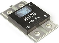
Relay Ya112V is also a "tablet", it is a "chocolate" and is usually sold complete with brushes, if the brushes are not worked out, then there is no point in buying new ones.
According to the auto repair manual, I checked the relay, as a result of which an open circuit was found in the relay circuit. There was another relay available, which recently came out of standing on the same car. I wondered what was going on and decided to open both. The relay turned out to be of two types.
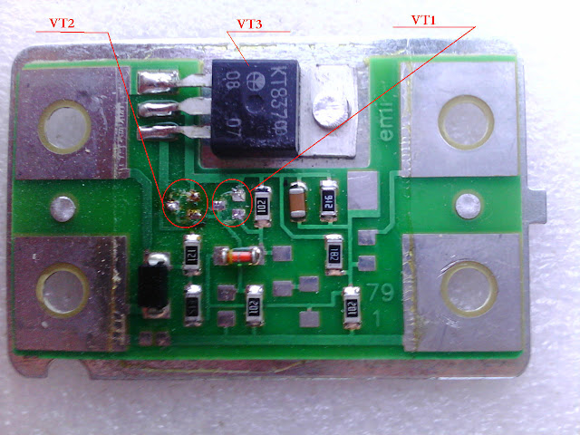
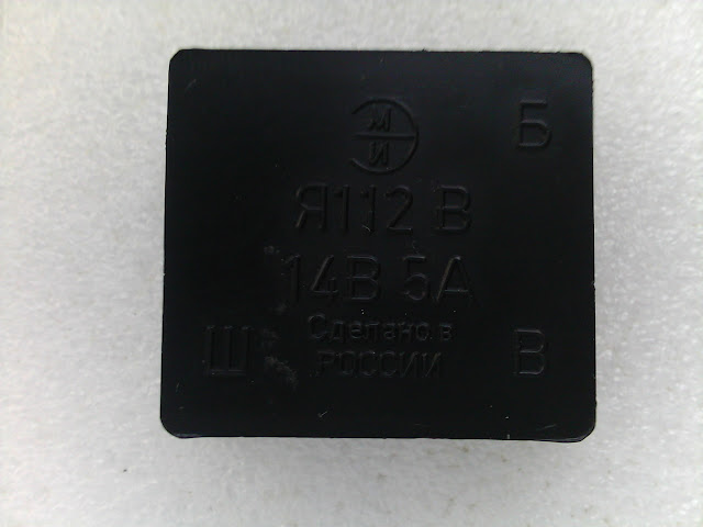
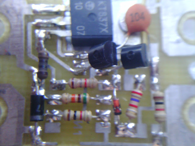
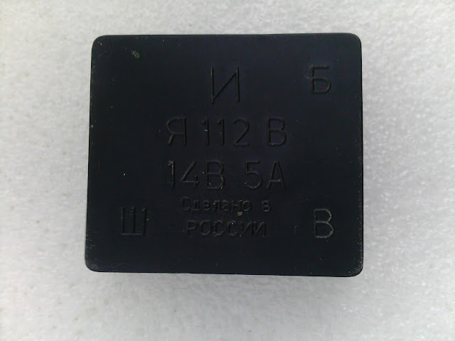
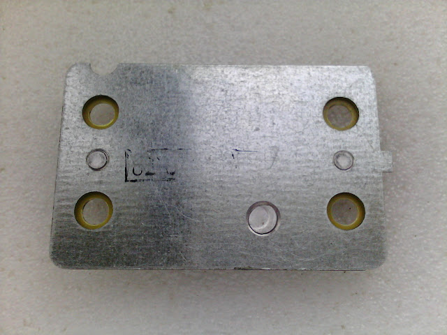
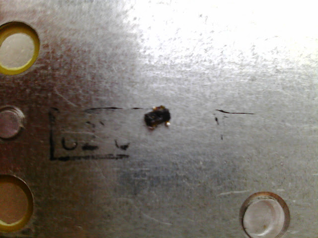
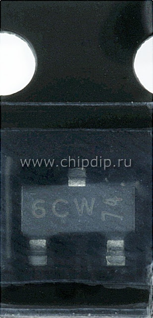
4 ohms and everything fell into place. An autopsy revealed that there was an interturn short circuit of the wires between the layers of the excitation winding. I replaced the rotor with a rotor from the G221 generator. The assembly took place at lightning speed. I repeated everything from beginning to end. The problem has been resolved. It all took about 3 days. To preserve the purity of thought, beer was not taken.
there was also a relay made on conventional parts, in which only the KT837F output transistor had to be replaced, the rest of the transistors were intact.
I replaced it like this: I drilled a rivet, bent the transistor so that it did not touch the metal plate, soldered it off the board. On the new transistor, I bent the legs like a burned out one, both in shape and in length. On the reverse side of the transistor, I applied a small amount of KPT-8 heat-conducting paste, soldered the transistor to the board, and instead of a rivet, pressed the transistor with a screw and nut. The screw was used with a head in “tie”, the nut was soldered to the transistor, and the screw head to the metal plate.
Regarding the parameters of stators and rotors of generators of various types:
________________________________________________________________________
Resistance of rotors, number of turns wire diameter
G221 = 4.3+0.2 ohm 500+3 0.69 mm
G222 = 3.7+0.2 ohm 460+3 0.71 mm
37.3701 = 2,6+0.1 ohm 420+6 0.80 mm
________________________________________________________________________
Stator, number of turns wire diameter
D221 = 10 1.25 mm
G222 = 9.0 0.95 mm
37.3701 = 8.5 1.00 mm
________________________________________________________________________
Replacing a generator on a car is a common procedure. The generator is not cheap and therefore some drivers have learned to repair it on their own.
In principle, there is nothing complicated in this. Moreover, if you use the step-by-step instructions described below.
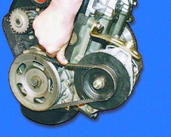
checking the tension of the alternator belt
A car generator is an important mechanism. A lot depends on him, and without his normal work, you won't go far.Malfunctions of the generator on the machine are usually associated with malfunctions in the battery.
Repair of the VAZ 2106 generator is inevitable in these cases. It can be complete or partial, and it all depends on the cause of the failures.
Most often they are associated with a tension belt or bearings.
Start checking the generator with the drive belts, or rather, its sufficient tension.Belt tension is essential for proper generator operation.
We can confidently say that the operation of the water pump and even the bearing of the crankshaft itself depends on a correctly tensioned belt. Loosening the strap will not generate enough electricity for the battery to function properly.
If its tension is too strong, the generator itself often breaks down. It is recommended to change the belt every 15 tons. Well, when cracks, tears or delamination are noticed on it, then even more so.
So, let's start checking.
For this:
- we drown the car (it is advisable that he stood on the pit, since it is more convenient to work with the belt under the machine);
- we raise the car on a jack if it is not put on a pit;
- remove the protective crankcase;
- we squeeze the belt with our hand up in the center between the pulleys of the generator and the crankshaft (we do not press hard);
- we measure the amount of deflection using a ruler (it should be no more than 10-15 mm).
The discrepancy between the deflection value and the required figures forces the tensioning belt to be adjusted.
Adjusting the VAZ 2106 belt, the repair of the generator of which directly depends on this, implies the following:
- loosening the lower and upper generator mounting nuts;
loosening the lower and upper generator mounting nuts
- diverting the generator from the cylinder block;
- turning the bolt clockwise (two full turns are enough);
drive belt adjustment bolt
- checking the belt tension (if the belt is too tight, then you need to turn the bolt counterclockwise);
- securing the generator in place.
The VAZ 2106 generator, the repair of which is associated with a tension belt, implies a competent approach to business. Indeed, with high tension, increased loads on the bearings of the generator itself and the tension roller are possible, as a result of which they will quickly fail.
With a weak belt tension, it will constantly slip on the pulleys, which will directly affect the operation of the battery.
In cases where the belt cannot be adjusted, it is replaced.
And for this, actions of the following kind are carried out:
- the bolts on the upper and lower mounting of the generator are loosened (the adjusting bolt is also unscrewed by half);
- the generator is moved as close to the cylinders as possible;
- the belt is removed from the generator pulley and crankshaft;
- a new belt is first put on the crankshaft pulley and then on the alternator pulley (in case of difficulty, it is recommended to turn the crankshaft slowly until the belt is put on);
- check belt tension.
Often times, the cause of a generator failure is within the generator. To do this, the generator must be removed and disassembled.
So, we carry out the following actions:
- remove the generator;
- mark a longitudinal mark on it with a felt-tip pen (it will come in handy during assembly);
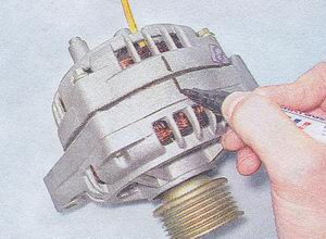
marking a longitudinal line on the generator with a marker
- we manually wring out the latches on the top cover (there are three of them);
- remove the cover;
- unscrew the two screws securing the voltage regulator;
- disconnect the wire from the regulator terminal;
- unscrew the screw securing the capacitor;
- we unscrew the screws fixing the block itself (there should be four of them);
- we take away three wires with terminals in order to remove the rectifier unit;
removing the rectifier unit
- unscrew the contact bolt nut from the rectifier unit;
- remove the washer with a spacer fork;
- we change the capacitor;
- remove the tip of the capacitor wire from the contact bolt;
- we unscrew the four screws holding the flat and spring washers (they are clamped very tightly, therefore it is recommended to use an extension wrench);
- pry off the generator cover from the side of the slip rings with a screwdriver;
- we clamp the generator rotor in a vice and unscrew the nut that secures the pulley;
- remove the pulley itself and the spring washer;
- remove the thrust washer;
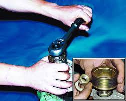
removing the nut securing the pulley
- there is a rotor on the drive side, which must be removed;
- we take out the spacer ring from the rotor shaft;
- we check the slip rings and if they have scuffs, cracks and similar defects, it is required to grind them with fine sandpaper (often this is done on a lathe, followed by processing with sandpaper);
- using an ohmmeter, we check the resistance of the rotor winding by connecting wires to the slip rings (if the tester shows an infinite value, then there is an open circuit and the rotor should be replaced);
- we check with a control lamp the presence of a short circuit in the winding of the rotor body (the photo below shows how to do this);
- proceed to inspect the stator;
- we examine it carefully, trying to find traces of the armature rubbing (if similar symptoms are observed, the bearings are replaced or the general generator cover together with the bearings);
- we check the stator winding with an ohmmeter for an open circuit (for this we connect the test lamp to the output of the stator winding, and the wire from the current source to the body - if the lamp lights up, then the winding or the entire stator needs to be replaced);
- Do-it-yourself repair of the generator also implies an inspection of the generator cover from the drive side (if you feel a backlash during the rotation of the bearing or jamming, or there are traces of grease leakage, or cracks are found in the attachment points, then it is necessary to replace the cover along with the bearings);
- it is also necessary to check the free rotation of the bearing (if there is a play between the rings or jamming, the bearing is replaced);
- we check the generator cover from the side of the slip rings (if serious defects are found, it is replaced with a new one);
- we collect everything in the reverse order, as the instructions indicate (it is necessary to close the cover, on which the line is marked with a marker, and put the pulley spring washer with the convex side to the nut).
| Video (click to play). |
This completes the repair of the VAZ 2106 car generator. It is only necessary to highlight a few points. When tightening the last spring washer, a torque of 39-62 Nm can be used.
To make it easier to work with the generator mounting nuts, the battery must be removed. For the convenience of unscrewing the nuts, it is advisable to use a head with a cardan joint and an extension.
When working with the generator, it is recommended to use keys for 10, 17 and 19. It is advisable to remove the generator in the inspection pit or after lifting the car on a jack. That's all there is to it!
The step-by-step instructions given above will help many motorists save good money, because the price of a new generator is quite high today.


