In detail: do-it-yourself repair of the g222 generator from a real master for the site my.housecope.com.
In my vaz2107, the battery charge voltage disappeared, because the generator did not work. I dismantled the faulty G222 generator (aka G221 with a slightly modified rear cover - there is another threaded hole for attaching the Y112V relay).
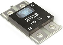
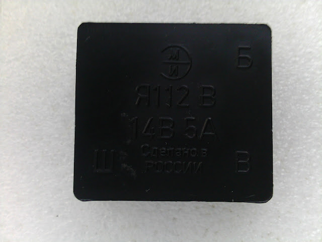
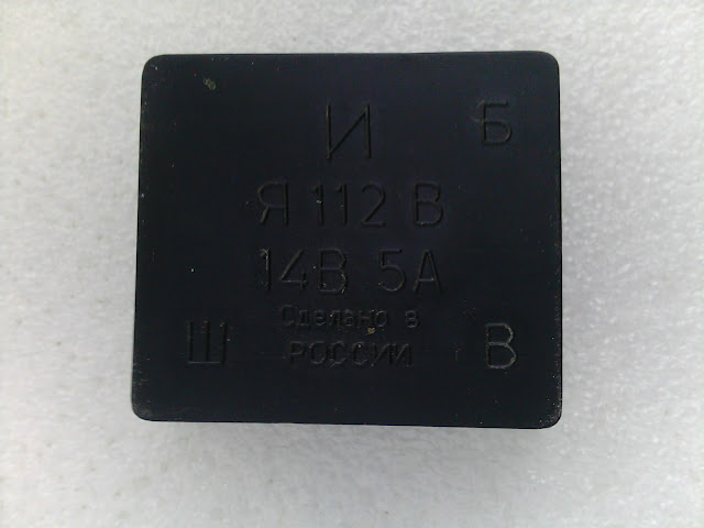
Relay Ya112V is also a "tablet", it is a "chocolate" and is usually sold complete with brushes, if the brushes are not worked out, then there is no point in buying new ones.
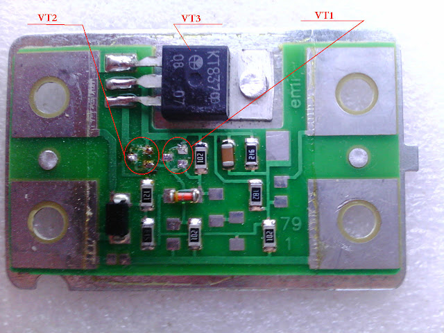
According to the auto repair manual, I checked the relay, as a result of which an open circuit was found in the relay circuit. There was another relay available, which recently came out of standing on the same car. I wondered what was going on and decided to open both. The relay turned out to be of two types.
4 ohms and everything fell into place. An autopsy revealed that there was an interturn short circuit of the wires between the layers of the excitation winding. I replaced the rotor with a rotor from the G221 generator. The assembly took place at lightning speed. I repeated everything from beginning to end. The problem has been resolved. It all took about 3 days. To preserve the purity of thought, beer was not taken.
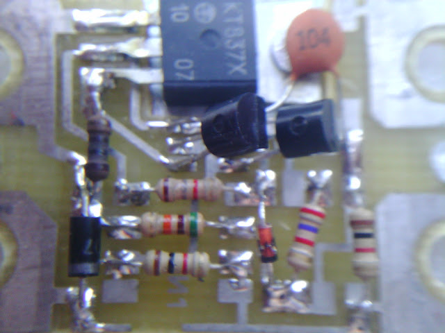
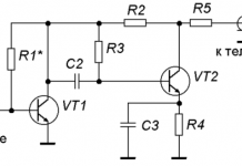
there was also a relay made on conventional parts, in which only the KT837F output transistor had to be replaced, the rest of the transistors were intact.
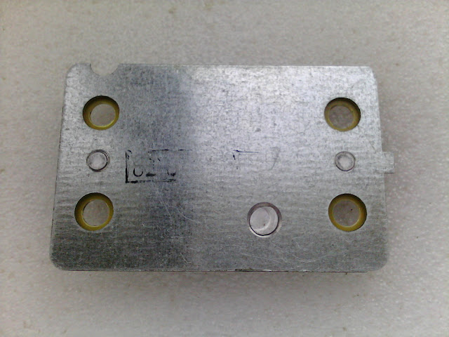
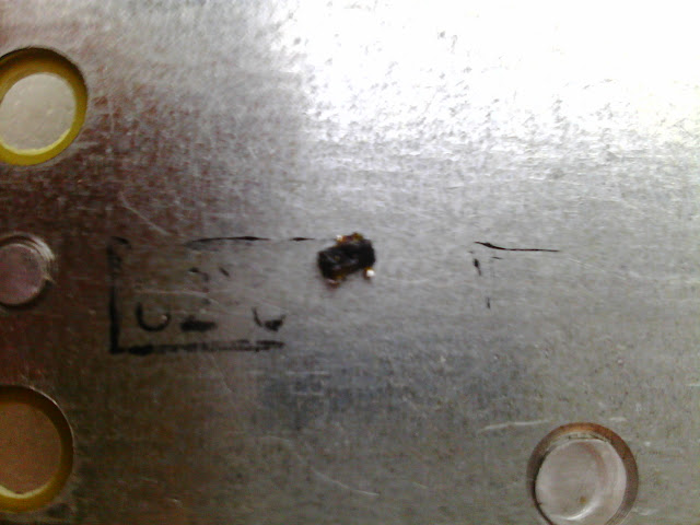
I replaced it like this: I drilled a rivet, bent the transistor so that it did not touch the metal plate, soldered it off the board. On the new transistor, I bent the legs like those of the burned out one, both in shape and in length. On the reverse side of the transistor, I applied a small amount of KPT-8 heat-conducting paste, soldered the transistor to the board, and instead of a rivet, pressed the transistor with a screw and nut. The screw was used with a head in “tie”, the nut was soldered to the transistor, and the screw head to the metal plate.
| Video (click to play). |
Regarding the parameters of stators and rotors of generators of various types:
________________________________________________________________________
Resistance of rotors, number of turns wire diameter
G221 = 4.3+0.2 ohm 500+3 0.69 mm
G222 = 3.7+0.2 ohm 460+3 0.71 mm
37.3701 = 2,6+0.1 ohm 420+6 0.80 mm
________________________________________________________________________
Stator, number of turns wire diameter
D221 = 10 1.25 mm
G222 = 9.0 0.95 mm
37.3701 = 8.5 1.00 mm
________________________________________________________________________
This unit is in question
To provide electrical energy to the electrical appliances of a VAZ 2105 car, as well as to recharge its battery while the engine is running, a generator is present in the car. Until 1987, units of the G 222 model were installed in the VAZ 2105, and later - the 37.3701 model. In both cases, the generator is a three-phase electrodynamic device, in which the sinusoidal voltage of each of the phases is rectified using a built-in rectifier. This part is a three-phase diode bridge of the VAZ generator, consisting of six silicon diodes. The voltage is produced by exciting the rectifier with three stator windings when changing the rotor poles under them. The rotor poles change polarity during its rotation inside the stator, and to increase the value of the magnetic fluxes, it has an electromagnetic field winding inside the magnetic cores. The rotor rotates through a belt drive from the front pulley of the engine crankshaft (injector) along with the pulley of the coolant pump.
The electrical circuit of the VAZ 21053 car differs from the instrument circuit of the model 2105 in that it has an electronic engine control system (ECM) and various additional sensors. Therefore, on the VAZ 21053, the power supply system has a different form of terminals than in 2105. The ignition switch of the first model, when the starter is turned on, turns off the secondary circuits and devices.
In general, the VAZ 21053 and 2105 generators are identical.But how to connect a generator to a VAZ 21053, because in this model the injector needs more power of the generated current? And how to connect a generator from "ten" for 80 A? The fastening, wiring diagram for the VAZ 21053 are the same with it, so there will not be a particular problem here.
The generator body consists of two aluminum alloy covers, tightened by four bolts and nuts, between which a round stator core is clamped. The rotor bearings are installed in the covers: the front one is in the through, the rear one is in the blind seat of the cover. The rotor rotates inside the stator and housing on two bearings. At the front end it has a slot for a key, a thread for a fan nut. An adjusting washer is installed between the front rotor and the front bearing, which is often forgotten when repairing the generator. At the rear end of the rotor shaft, in front of the rear bearing, two copper slip rings are pressed, isolated from the shaft and connected to the ends of the field winding.
A BPV6-50 rectifier is installed to the inside of the rear cover. It consists of two insulated horseshoe-shaped aluminum busbars, into which three VA-20 silicon diodes (valves) are pressed. The inner bus is isolated from the case, but connected to the generator terminal “30” bolt, while the other is in contact with ground. The legs of the diodes in pairs from each bus are bolted to the ends of the stator phase windings, and their other ends are connected together - a "star" connection. In the G 222 generator, a wire goes from this point to a terminal on the rear cover, from which a wire goes to terminal "85" of the RS-702 type charge control lamp relay. There are no wires at 37.3701 from the common point of the phase windings.
Brushes are pressed to the rotor slip rings by springs, one of which is connected to the "B" terminal, and the second to the W terminal of the voltage regulator installed on the brush assembly in the upper rear part of the generator. In 37.3701 there are three diodes connected at one end to the phase windings, and the second are connected to one point, the wire from which goes to the terminal Ш of the regulator relay and the terminal "61" on the rear surface of the generator. The diodes are connected in such a way that they pass positive half-cycles to the terminal "61".
The electronic voltage regulator is non-separable and since 1996 has been installed in a metal case, riveted to the brush holder. A capacitor is mounted between the body and terminal "30".
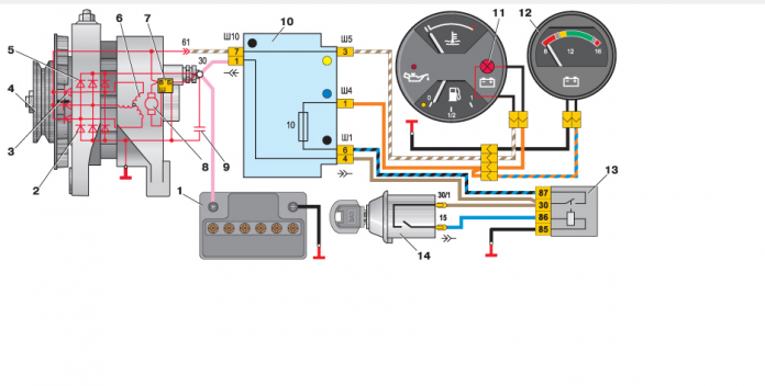
Generator connection diagram
To control the battery charge level in a VAZ 2105 car, you need to monitor the output rectified voltage, which is maintained within 13 June 14.2 V. The regulator relay compares the voltage in the vehicle's on-board network with the reference one and, if this level is exceeded, reduces the voltage on the exciting winding , increasing the resistance between one of the rotor brushes and the "mass". When the voltage in the car's network decreases, the regulator lowers the resistance, increasing the current in the field winding and, accordingly, the voltage at terminal "30". Such cyclical processes occur at a frequency of 50-250 times per second.
The generator ground is connected to the vehicle ground through a housing attached to the engine block. Terminal "30" of the generator is connected to the "+" terminal of the storage battery and the on-board network of the car through the fuse box. Outgoing to the output on the back cover of the generator Г 222, the wire from the "zero" of the stator winding is connected to the terminal "85" of the PC-702 relay of the charge control lamp. The wire from terminal "87" of this relay through the connector Ш10 and Ш5 of the mounting block goes to the charge indicator lamp through the connector "2" of the instrument cluster.
In the 37.3701 generator, terminal "61" is connected with a brown wire with a white stripe to the Ш10 connector of the mounting block and through the Ш5 connector of this block and connector "2" of the instrument cluster is connected to the charge indicator lamp.
The generator model G 222 works like this. When the ignition "+" is turned on, the voltage from the battery is supplied to terminal "30", then to the excitation winding, and then through the open voltage relay to ground.From the ignition switch through the fuse 10 of the mounting block "+" is connected to the terminals "86" and "87" of the charge indicator lamp relay. Through the closed contacts of the relay, it is supplied to the lamp itself and through it along the "mass" of the car to the "-" of the battery. The lamp is on.
When the G 222 rotor rotates on the VAZ 2105, a voltage arises at the ends of its phase windings, which, increasing, begins to partially, and then completely supply the excitation winding, the on-board network and charge the battery. When the upper voltage level in the network is reached, the regulator relay increases the resistance in the excitation circuit and the generator keeps it within 13, June 14.2 V. A phase voltage is applied to the winding of the charge indicator lamp relay, and when its value is 5.03 oct 4 V, this is enough to open the contacts. The lamp goes out, indicating that all appliances are powered by the generator.
In the model 37.3701 generator, when the ignition is turned on, the excitation winding is powered through a control lamp, which is on at this time. When the rotor rotates, a voltage arises at the ends of its phase windings, it is rectified by a block of additional diodes, begins to feed the excitation winding and is fed to the charge control lamp. The lamp is on from the voltage difference at the terminals "61" and "+" of the battery. With an increase in the voltage at terminal "30", the indicated difference with the engine running decreases and reduces to 0. The lamp goes out, indicating that all devices are powered by the generator.
Sometimes, when tuning or repairing electrical equipment on a model 2105 before 1987, a generator is installed from a VAZ 2108 or 21053. And the car immediately starts having problems: then there is no charge, then the lamp does not burn. You need to connect the "+" of the on-board voltage to the lamp, and its second contact, bypassing the relay, connect to the terminal "61", then everything will fall into place.
The generator G-222 and 37.3701 (from 2108) were installed at 2105. So which one did you set?
Most likely you installed the generator 37.3701 - read the topic Replacing the standard generator with a VAZ-2108 ead.php? T = 12163
- Like
- I do not like
After several days of brain-fucking with my generator as a "guru" of generator set-up, I want to report the following:
I have not seen it anywhere in the recommendations, but if you have already checked everything that is possible, things are still there.
Then my advice to you is to check if the stator (winding) is broken to ground. In the G-222 generator, this check is easily done without disassembly:
- We take a multimeter
- remove the lamp relay terminal and check the resistance between the ground and the zero terminal of the winding (the one to which the lamp relay is connected). If the resistance is zero or a few ohms, then go ahead to the market for a new winding or generator.
Yes, and, from personal experience, on repairing genes, so as not to fuck like me in case of problems with the gene, I advise the following verification scheme:
- we check the fuse of the excitation winding
- check the condition of the battery (its charge)
- check the belt tension
- we take a multimeter and removing the wire from the voltage regulator, we check the presence of voltage on it with the ignition on. (if there is no voltage or it is lower than the voltage on the battery by more than 1.5V, we check the entire circuit for oxides, including the ignition switch).
- we check the diode bridges with a multimeter (there is a description of how)
- check the winding breakdown to ground in the above described way
- with the same multimeter we check the quality of the mass on the generator case
-If the above did not help, we unscrew the voltage regulator with brushes, check the brushes, clean the mass and contacts on the regulator, change the regulator if necessary.
- through the nest of brushes with a multimeter, we check the excitation winding for an open circuit (we connect the multimeter to the collector contacts) and a breakdown to ground.
P / S do not judge strictly, I understand that a lot has been written on this topic, but I think my post may be useful to someone.
- Like
- I do not like


VAZ 2105 Generator Possible malfunctions, their causes and methods of elimination
Replace voltage regulator
Eliminate the short circuit or replace the plastic base of the brush holder
In general, during assembly, the contact that should touch the W terminal of the "tablet" ("chocolates" Ya112V1 ) moves and touches the fixing screw (the screw that secures the cover of the "chocolate" to the generator body)
Stator check:
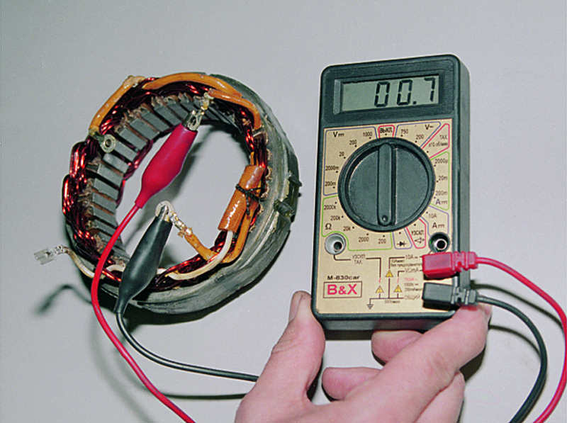
By alternately connecting the ohmmeter probes to the stator terminals, we check its windings for an open.
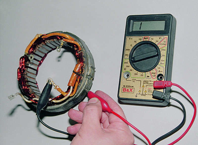
... and short circuit to the case.
Another important thing to know is that there should be no melted / damaged windings on the windings, and that there should not be turns on the coil hanging on the rotor. Very often, classic generators die due to acid from the battery - increased voltage (or inept addition of distilled water) splashes acid into the engine compartment.
Most importantly: if the amount for repairing a generator is more than half (1/2) of the cost of a new generator, buy a new generator
- Like
- I do not like


Please help me in this matter: sometimes (once or twice a month) the charging lamp lights up, and then it does not go out for several days, when the clamp is removed from the battery, the engine stalls. The charging relay is working, the brushes are replaced, the contacts are cleaned, the fuse 10 is working. what else could be with the gene?
is it possible to ring the dodny bridge and windings without removing the gene?
Does anyone have in mind a good electrician (or service station) in Dnepropetrovsk?
All greetings, dear friends and subscribers.
From the beginning about the painful; with the drive up to many cars, some kind of unsubscribing from my car began and this is regrettable) well, I wish good luck to everyone who unsubscribed and success.
Now about the repair of the Generator
It all started with the fact that the voltage dropped to 12V with the consumer dimensions, it was useful to see what could be there.
As always, I replaced the generator brushes, but it did not help, then I took off the generator (G222) and began to disassemble it, but it was a little wrong) the bearing that was in the cover did not want to be removed, I had to knock down the bottom cover a little and then the winding, but it happened that one contact from the winding came off, The contacts of the diode bridge were oxidized but not burnt out, so I decided to replace it.
I put everything in place now it remains to install the brushes.
The generator brushes are not my relatives
but very rare but good ones, when I tried to take them off I broke off one little cream, in half.
I went to look for the shops but did not find such, they advised me to take my family's quality from them, of course, HOMNO
but what to do I bought, put it on.
I put the generator back in place and started to start.
When I started my surprise there was no limit, the generator gave out a maximum of 19.2
The battery boils after 30 seconds of engine operation,
I took my old ones, which I put in place for more than 10 years, and voila Voltage at idle speed 14.3v with consumers 13.2v
Good luck to everyone and not high voltage)

In order to provide the VAZ-2105 with electricity for standard operation, there is a special electric generator in the car. Starting from the moment of its creation and until 1987, the VAZ-2105 was equipped with an aggregate G 222, after 1987 this model of the generator was replaced by the 37.3701 device.
A generator is a device that rectifies the sinusoidal voltage of each of the three phases, by means of the fact that an electric current rectifier is built into it.
This device consists of a three-phase diode bridge of a penny generator, which, in turn, has 6 silicon-based diodes in the structure. Electric voltage is created by excitation of the current rectifier at the moment when the rotor poles change under the stator windings. As the rotor rotates inside the machine stator, the rotor poles change. To increase the value of the magnetic fluxes, the stator contains an electromagnetic exciting winding in the area of the magnetic circuits.
The rotor belt drive rotates by the front crankshaft pulley together with the pump pulley of the cooling system.VAZ-2105, at the moment the starter is turned on, turns off all instrument circuits that are of secondary importance.
If it becomes necessary to switch the generator from the VAZ-2105 to the VAZ-21053, then there should be no problems, because the diagram of their electrical connections is practically the same.

- The generator consists of two covers made of aluminum alloys, which are tightened with bolts and nuts, with a round stator core clamped in the middle between them.
- The rotor bearings are located in the covers, the front one is located in the area of the through, the rear one is in the area of the blind seat. The rotor rotates inside the stator part, as well as inside the housing, thanks to two bearings.
- At the front end there is a special key slot, which is an ordinary thread for a fan nut.
When repairing a generator, they often forget to put an adjusting washer, which is highly discouraged.
- The BPV-50 current rectifier is connected to the back cover, namely to its inner part. The rectifier consists of two insulated from each other horseshoe-shaped aluminum busbars with three silicon diodes of the VA-20 type pressed into them. Inside, the bus is completely isolated from the case, it comes in close contact with the bolt through which the generator output 30 takes place, the second cinema bus maintains contacts with ground.
- Each bus has an output of diode legs connected in pairs by bolts to the ends of the phase stator windings. Their opposite ends are connected to each other in a "star" connection.
- The G 222 generator contains the wiring coming from this point, which is output to the terminal of the rear cover, from this cover to the 85 relay of the control lamp charge of the RS-702 type.
- The slip rings are connected by springs to the brushes. The first brush is connected to the outlet of the point "B", and the second - to the point "W", which regulates the voltage. The regulator outlet is installed in the brush assembly located in the region of the rear upper regulator part.
The voltage regulator cannot be disassembled. Since 1996, it has been riveted to the brush holder with a metal body. The case itself is separated by a capacitor from the 30th terminal.
To control the battery charge level, you need to carefully monitor the amount of rectified voltage maintained around 14.2 V.
The regulating relay compares the voltage within the on-board network of your vehicle with the reference one. If this level rises, then it begins to reduce the amount of voltage supplied to the exciting winding. In essence, this means an increase in the available resistance between one rotor brush and, accordingly, the mass.

The result is two masses:
They are connected to each other by a housing, and the housing itself is attached to the cylinder block of the engine.
Using the standard schematic description of the generator's operation, it is enough just to delve into its structure.
If you need to work with a remote voltage regulator, then it is advisable to remember that it is built-in on the VAZ-2105, and an external one must be installed on the VAZ-2101. As a result, when replacing from car to car, all this will give serious connection problems and a dead battery.
Diy video instructions for connecting a VAZ-2105 generator (carburetor, injector):
There is a special offer on our website. You can get a free consultation of our corporate lawyer by simply asking your question in the form below.
This article details the process DIY VAZ 2101 generator repair - disassembly, cleaning, replacement of non-working parts, assembly and installation.The generator will be repaired on the 37.3701 model (it is almost identical to the G222 model).
- Andycar bearings.
- Generator capacitor.
- Diode bridge.
- Nuts 8 (4 pcs).
- Relay regulator (if there is a need to replace it).
I decided not to change my regulator relay, because its condition suits me perfectly.
- A universal puller for removing the bearing, as an option, you can use a rod puller, but I warn you, this is very inconvenient.
- Also find a good metal brush and cloth backed sandpaper.
- Hammer.
- WD-40.
- Standard set of wrenches and screwdrivers.
This is how it looked generator VAZ 2101 before repair, remember it like this, because after the bulkhead it will change beyond recognition
DIY VAZ 2101 generator repair: disassembly, cleaning, replacement of parts
1. The first step is to clean the generator from dirt, dust, oil, in short, from everything that has accumulated on it over many years of operation.
2. Unscrew the pulley nut, to do this, lay the generator so that its pulley rests on the floor, then put the key on “19” on the nut. Holding the pulley with a wrench from turning, you need to apply several strong and accurate blows with a hammer to the wrench. It is unlikely that it will be possible to clamp the pulley “tightly” by hand, but this will be enough to “rip off” the nut for free unscrewing.
3. Using a “10” wrench, unscrew the four tie rod bolts that assemble the generator into one piece.
4. Take a chisel and knock out the key (see photo above), for this you need to install the generator so that the shaft is on top. Place the chisel on the key and start knocking it out by hitting the chisel with a hammer. 5. After the key is knocked out, remove the generator front cover. In case it goes tight, try knocking out on weight.
Read also:
6. Now remove the relay regulator from the generator.
7. Using the hole under the relay, knock out the rotor, for this you can take a drift. While knocking out, rotate the rotor constantly so that it does not warp.
8. Using the socket on “8”, unscrew the three fastening nuts of the stator, as well as the diode bridge. Here, attention must be paid to the bolts, if they are turned, hold them with pliers on the back side.
DIY VAZ 2101 generator repair: disassembly, cleaning, replacement of parts
9. It's time to remove the stator, before I did it I sprayed the joints with WD-40 fluid. When everything is a bit sour, we arm ourselves with a hammer again and begin to knock it out. During execution, be extremely careful and careful not to damage anything. When the stator is removed, you need to get the diode bridge. Unscrew the capacitor and press out the rear rotor bearing using the universal puller mentioned at the beginning of the article.
10. Now unscrew the front cover and pull-off plates. The locked bolts that are installed there can be damaged, so at the beginning I did not in vain mention that it is necessary to buy four nuts for “8”. To prevent the bolts from turning when unscrewing, clamp them with pliers on the other side.
11. Remove the plates, then the bearing must be extruded through the mandrel.
As you can see generator VAZ 2101 now it has been completely disassembled, now everything needs to be cleaned, washed, scrubbed, etc. I will not go into details, since I think how to do this is so clear. You will need a metal brush, sandpaper and a knife.
Draw your attention on the fact that since 1996 the place of withdrawal of contact 61 has changed.
My old diode bridge is "old-style", the differences are clearly visible in the photo, on the old one the contact is located on the wire, and on the new one it is soldered into the diode bridge.
Press the bearings into place in the same way, through the mandrel. An important point - when pressing the rear bearing onto the rotor, you need to put the mandrel only on the inner bearing race, while pressing the front one you need to do the opposite - put on the outer one. If you ignore this rule, you can damage the bearing.
You may be interested in:
The rest generator assembly is carried out in the reverse order.Those who had an old-type diode bridge installed will have to tinker with pin 61, it does not fit well into the hole in the back cover. Personally, nothing else came to my mind other than just finishing the hole with a file.

Advice : I recommend sanding the seating plane of the capacitor, this will improve the contact and make it more stable. The rotor is again hammered with a hammer and light blows. At the end of the assembly, do not forget to lock the bolts with a chisel.
This completes the repair of the VAZ 2101 generator, it remains to install it on the car and test it in action. I hope my detailed photo report helped you. Thank you for attention! Those who wish to supplement the article can use the comment form.
The generator is disassembled for a complete check and validity of its elements and replacement of faulty stator, rotor, its bearings and rectifier unit.
You will need: keys "for 8", "for 10", "for 13" and "for 19", socket heads "for 8", "for 10" and "for 19", a knob, a torque wrench, a screwdriver, a vernier caliper, hammer, mandrels for pressing and pressing generator bearings, generator pulley puller.
1.Loosen the screw securing the generator brush holder and remove the brush holder.
2. Unscrew the alternator pulley fastening nut by clamping the alternator pulley in a vise through the belts (use a standard alternator belt and some kind of large-section drive belt, for example, from a truck).
3.Using a puller, press the pulley off the generator rotor shaft.
4. Remove the alternator pulley key.
5. Unscrew the four nuts securing the cover from the side of the slip rings (back cover), remove the spring washers.
6. Remove the back cover of the generator together with the stator.
7. Remove the rotor and rear bearing assembly from the generator front cover. Do not lose the spacer ring fitted to the rotor shaft (arrow).
8. Unscrew the nuts securing the front bearing caps by filing the bored ends of the screws.
9. Remove the screws, front bearing inner and outer caps.
10. Press the front rotor shaft bearing out of the front cover using an appropriate diameter mandrel.
11.Unscrew the three nuts securing the stator winding leads from the rectifier unit, remove the spring washers, remove the bolts with insulating spacers.
12. Remove the tip of the wire from the terminal block "67" inside the back cover of the generator, pushing it with a screwdriver, and separate the back cover and stator.
13. Unscrew the nut securing the output "30", remove the lock and flat washers, as well as the nylon insulating spacer.
14. Remove the rectifier unit from the generator back cover.
15.Use a puller to press the rear bearing off the rotor shaft.
16. Before installation, check the condition of the generator brushes and measure their protrusion from the brush holder (should be at least 12 mm).
17. Assemble the generator in the reverse order of disassembly.
After tightening, tighten the nuts of the screws that secure the front bearing caps (see step 8) to prevent them from self-loosening.
Details of the generator 37.3701
1 - voltage regulator assembled with a brush holder for exhaust generators
since 1996;
2 - voltage regulator and
brush holder for generators manufactured before 1996;
3 - block for outputting additional diodes;
4 - insulating bushings;
5 - rectifier unit;
6 - contact bolt;
7 - stator;
8 - rotor;
9 - distance sleeve; 10 - inner washer of bearing fastening;
11 - cover from the drive side;
12 - pulley;
13 - outer washer of bearing fastening;
14 - tie bolt;
15 - rotor front ball bearing;
16 - bushing;
17 - cover from the side of slip rings;
18 - buffer sleeve;
19 - clamping sleeve;
20 - capacitor
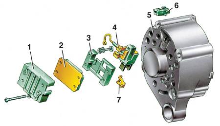
Details of the front of the generator G-222
1 - casing;
2 - voltage regulator;
3 - base;
4 - brush holder with brushes;
5 - generator cover from the side of slip rings; 6 - block of the plug of the central output of the stator winding;
7 - output "15" of the generator (output "B" of the voltage regulator)
The tool kit 67.7823.9504 includes a conventional puller and gripper. The latter consists of two steel half rings, which are inserted into the pulley stream. The half rings have the same cross section as the alternator drive belt. On the one hand, they are pivotally connected, and on the other, they are equipped with levers that are compressed with one hand when the pulley is removed.
GENERATOR 37.3701
1. Clean and blow out the generator with compressed air.
2. Lock the alternator pulley with the grab supplied with special tool 67.7823.9504, unscrew the pulley retaining nut and press the pulley with a puller. Remove the key and tapered pulley washer.
3. Disconnect the wire from the "B" plug of the voltage regulator.
4. Disconnect the regulator and capacitor wires from the generator terminal “30” and remove the screws securing the voltage regulator.
5. For generators of release before 1996, so as not to break the brushes when removing the brush holder, insert a screwdriver blade between the regulator body 2 (see Fig. Parts of the generator 37.3701) and the brush holder and partially pull the regulator out of the generator, leaving the brush holder in place.
6. After that, tilt and remove the regulator together with the brush holder from the generator. Remove the capacitor 20 by unscrewing the fastening screw.
7. Unscrew the nuts of the tie bolts 14 and remove the cover 11 of the generator and the rotor 8. Unscrew the nuts of the screws connecting the tips of the diodes with the terminals of the stator winding and remove the stator 7 from the cover 17 of the generator.
8. Unscrew the nut of the contact bolt 6, disconnect the plug of the additional diode wire from the block 3 and remove the rectifier unit 5.
GENERATOR G-222
1. The G-222 generator is disassembled in the same order. To remove the voltage regulator, it is necessary to unscrew the fastening screws and remove the casing 1 (see Fig. Details of the front part of the G-222 generator) assembled with the regulator 2, base 3 and brush holder 4.
2. Then, after unscrewing the screws, separate the regulator, base and brush holder with brushes.
3. Further disassembly of the G-222 generator is similar to disassembly of the 37.3701 generator.
- Thank you
- I do not like
- Thank you
- I do not like


I bought the g-222 generator, since the old one didn’t charge the battery anymore, and there was no time to bother with disassembly. I just bought g-222, and the old one stood at 37.3701. How to connect the g-222 generator to the circuit without major alterations? Auto VAZ21053 99 of release. I could not find an answer in the forum, I had to create a separate topic for this problem. Friends, for sure a similar task has already occurred to someone, share your experience, tell me how to solve the problem.
look here: showtopic = 29697 - I laid out the connection diagrams for both generators.
- Thank you
- I do not like
look here: showtopic = 29697 - I laid out the connection diagrams for both generators.
I already have the schemes, thanks for the link. But I'm not very good at electrics. On my old generator (37.3701) there were 61 pins and 30, there was also a connector on the voltage regulator to which the wire coming out of the generator was connected. On g-222 30, the contact is the same, instead of 61 there is 0, and the voltage regulator also has a connector, but no wires come out of the generator. So with the 30th everything is clear, I connected it as it was. But tell me what to do with the rest of the connectors? What to connect to the free connector of the voltage regulator and what to the 0th connector on the generator, and where to connect the wire that was on pin 61? I'm afraid I won't understand the scheme, if you can explain on your fingers what is where. Somewhere I read that a jumper is also put in the mounting block on Ш11 between contacts 3 and 4, but I did not find a list of actions for installing g-222 instead of 37.3701 on the Internet.
- Thank you
- I do not like


- Thank you
- I do not like
the wire that went to 61 is connected to 0 (it is better to put the relay according to the scheme), but 15 is ignition - you will have to drag an additional wire.
So the free connector on the voltage regulator is the 15th? And what should be the characteristics of the ignition wire?
Do I understand correctly that by connecting the wire from 61 to 0 (let's say without a relay) and stretching the wire from 15 to the ignition switch, and without making any more changes, the generator will work as needed? And you don't need to put any jumper on Ш11 4 and 3 contacts?
- Thank you
- I do not like


So the free connector on the voltage regulator is the 15th? And what should be the characteristics of the ignition wire?
Do I understand correctly that by connecting the wire from 61 to 0 (let's say without a relay) and stretching the wire from 15 to the ignition switch, and without making any more changes, the generator will work as needed? And you don't need to put any jumper on Ш11 4 and 3 contacts?
Ш11 3 and 4 this is the ignition, only with different fuses. And 61 is the output to the charging lamp. The relay of the charge lamp (in the diagram, it simply supplies mass to the lamp), the lamp may work without a relay (plug in and turn on the ignition - if the light comes on, it will live, if not, put the relay on). Good luck.
- Thank you
- I do not like
Colleagues, tell me why put g-222 instead of 37.3701?
If he is referring to the characteristics is worse:
Maximum recoil current at 13 V and rotor speed 5000 min – 1, A 55 (45 *)
Regulated voltage limits, V 14,1 ± 0,5
Maximum rotor speed, min – 1 13000
Gear ratio engine-generator 1:2,04
* For the G-222 generator.
- Thank you
- I do not like


Colleagues, tell me why put g-222 instead of 37.3701?
If he is referring to the characteristics is worse:
Maximum recoil current at 13 V and rotor speed 5000 min – 1, A 55 (45 *)
Regulated voltage limits, V 14,1 ± 0,5
Maximum rotor speed, min – 1 13000
Gear ratio engine-generator 1:2,04
* For the G-222 generator.
After all, everyone has a different way: I have G222 for 200 rubles. I gave it away, I didn’t give it up, I’ll burn my own, I won’t think any more.
After all, everyone has a different way: I have G222 for 200 rubles. I gave it away, I didn’t give it up, I’ll burn my own, I won’t think any more.
This is understandable, it is good if the author also bought for such a price, but if there was a choice, then in vain, since if he has a lot of bulbs and equipment, then it may not be enough, especially if you stand in a traffic jam all the time. On Zhiguli it is necessary to put 80 amp generators and accumulators. I read about it somewhere, but I have not yet pressed on the 55th drive.
- Thank you
- I do not like
- Thank you
- I do not like
I ran into the same problem as the author of the topic. But in electrics, I do not understand much at all.
In this regard, please: if you can point by point what to disconnect from and what to connect where.
Buy a circuit for a start, And buy a battery charge indicator lamp relay, and more wires
- Thank you
- I do not like
I ran into the same problem as the author of the topic. But in electrics, I do not understand much at all.
In this regard, please: if you can point by point what to disconnect from and what to connect where.
the relay that you buy will have their outputs 4. 85,86,87,30
- Thank you
- I do not like
Please share your experience in increasing the efficiency of the ROTOR.
My goal:
When the battery voltage is applied to the rotor, I want to teach the G222 to rotate the rotor, ELECTRICALLY. THOSE. from the same battery.
Please share your experience in increasing the efficiency of the ROTOR.
My goal:
When the battery voltage is applied to the rotor, I want to teach the G222 to rotate the rotor, ELECTRICALLY. THOSE. from the same battery.
A useless thought Previously, there were DC generators on cars. When the voltage was applied, it (the generator worked like an electric motor. They made emery from them)
- Thank you
- I do not like
| Video (click to play). |
Please share your experience in increasing the efficiency of the ROTOR.
My goal:
When the battery voltage is applied to the rotor, I want to teach the G222 to rotate the rotor, ELECTRICALLY. THOSE. from the same battery.

